u blox EMMYW165 WLAN/Bluetooth/NFC host-based multiradio module EMMY-W1 User Manual NEO 7
u-blox AG WLAN/Bluetooth/NFC host-based multiradio module EMMY-W1 NEO 7
u blox >
Contents
- 1. EMMY-W1_User_Manual
- 2. Data Sheet
- 3. EMMY-W1_AntennaReferenceDesign
EMMY-W1_User_Manual
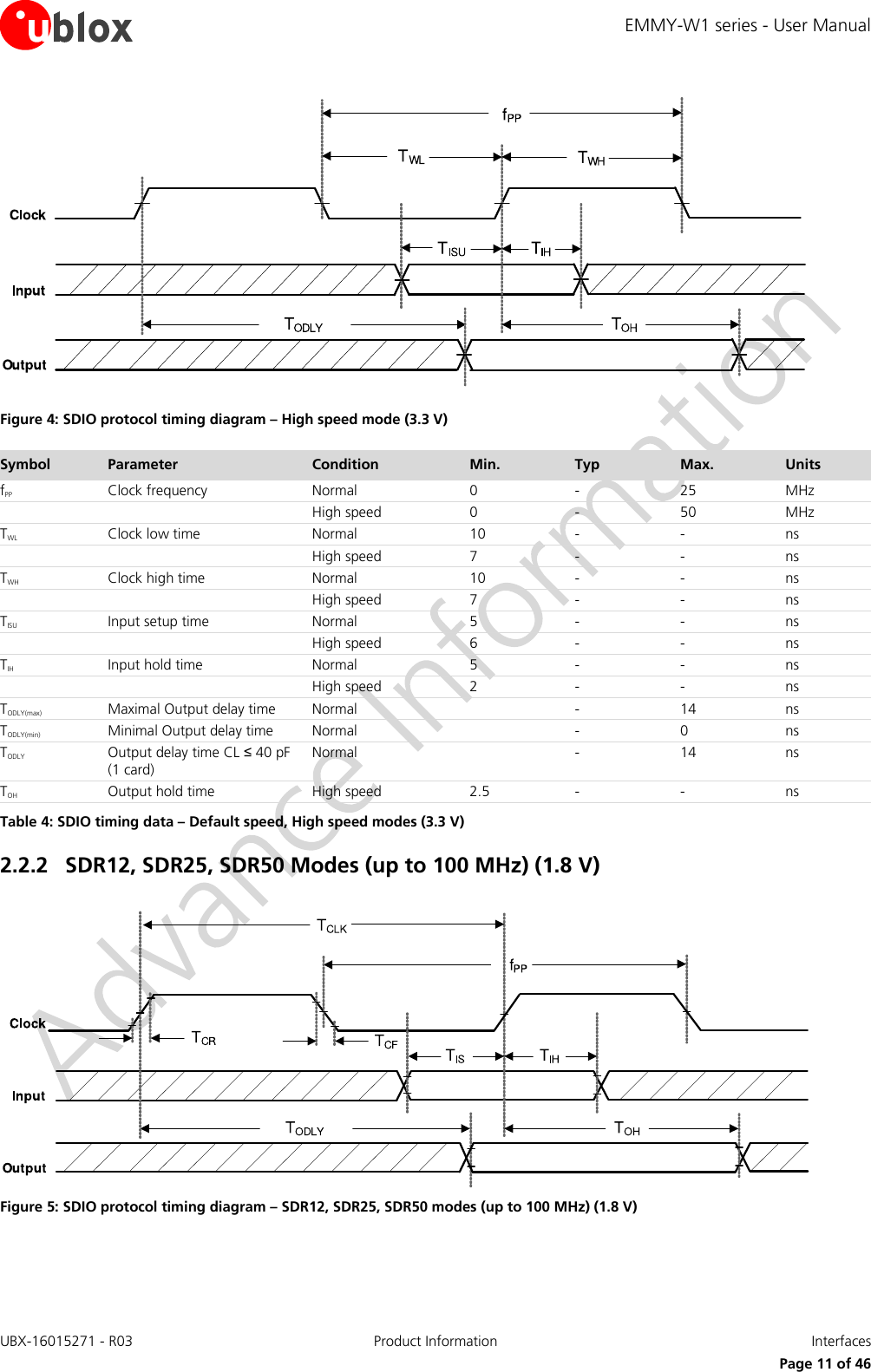
![EMMY-W1 series - User Manual UBX-16015271 - R03 Product Information Interfaces Page 13 of 46 2.2.4 DDR50 Mode (50 MHz) (1.8 V) Figure 7: SDIO CMD timing diagram – DDR50 mode (50 MHz) Figure 8: SDIO DAT[3:0] timing diagram – DDR50 mode (50 MHz)](https://usermanual.wiki/u-blox/EMMYW165.EMMY-W1-User-Manual/User-Guide-3172302-Page-13.png)
![EMMY-W1 series - User Manual UBX-16015271 - R03 Product Information Interfaces Page 14 of 46 Symbol Parameter Condition Min. Typ Max. Units Clock TCLK Clock time 50 MHz (max) between rising edges DDR50 20 ns TCR, TCF, Rise time, fall time TCR, TCF < 4.00 ns (max) at 50 MHz CCARD = 10 pF DDR50 0.2*TCLK ns Clock Duty DDR50 45 55 % CMD Input (referenced to clock rising edge) TIS Input setup time CCARD ≤ 10 pF (1 card) DDR50 6 ns TIH Input hold time CCARD ≤ 10 pF (1 card) DDR50 0.8 ns CMD Output (referenced to clock rising edge) TODLY Output delay time during data transfer mode CL ≤ 30 pF (1 card) DDR50 13.7 ns TOHLD Output hold time CL ≥ 15 pF (1 card) DDR50 1.5 ns DAT[3:0] Input (referenced to clock rising and falling edges) TIS2x Input setup time CCARD ≤ 10 pF (1 card) DDR50 3 ns TIH2x Input hold time CCARD ≤ 10 pF (1 card) DDR50 0.8 ns DAT[3:0] Output (referenced to clock rising and falling edges) TODLY2x (max) Output delay time during data transfer mode CL ≤ 25 pF (1 card) DDR50 7.0 ns TODLY2x (min) Output hold time CL ≥ 15 pF (1 card) DDR50 1.5 ns Table 7: SDIO timing data – DDR50 mode (50 MHz) 2.3 High Speed UART interface The EMMY-W1 series modules support a high speed Universal Asynchronous Receiver/Transmitter (UART) interface in compliance with the industry standard 16550 specification. The main features of the UART interface are: FIFO mode permanently selected for transmit and receive operations 2 pins for transmit and receive operations 2 flow control pins Interrupt triggers for low-power, high throughput operation High throughput (4 Mbps) The UART interface operation includes: Uploading the firmware to the module Supporting data input/output operation for peripheral devices connected through a standard UART interface Baud Rate 1200 38400 460800 1500000 3000000 2400 57600 500000 1843200 3250000 4800 76800 921600 2000000 3692300 9600 115200 1000000 2100000 4000000 19200 230400 1382400 2764800 Table 8: Supported UART Baud rates](https://usermanual.wiki/u-blox/EMMYW165.EMMY-W1-User-Manual/User-Guide-3172302-Page-14.png)
![EMMY-W1 series - User Manual UBX-16015271 - R03 Product Information Interfaces Page 17 of 46 GPIO Function GPIOP Pin 0 1 2 3 4 5 6 7 8 9 10 11 12 13 14 15 16 17 General Input X X X X X X X X X X X X X X X X X X Output X X X X X X X X X X X X X X X X X X LEDs LED output7 - - X X - - - - - - - - - - - - - - Interrupts Input X X X X X X X X X X X X X X X X X X Table 11: GPIO Functions – GPIO [17:14], [12:0] GPIO_12 is not available. 7 GPIO [2] is used for Wi-Fi activity while GPIO [3] is used for Bluetooth activity.](https://usermanual.wiki/u-blox/EMMYW165.EMMY-W1-User-Manual/User-Guide-3172302-Page-17.png)
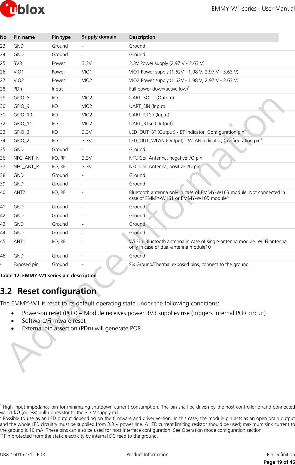
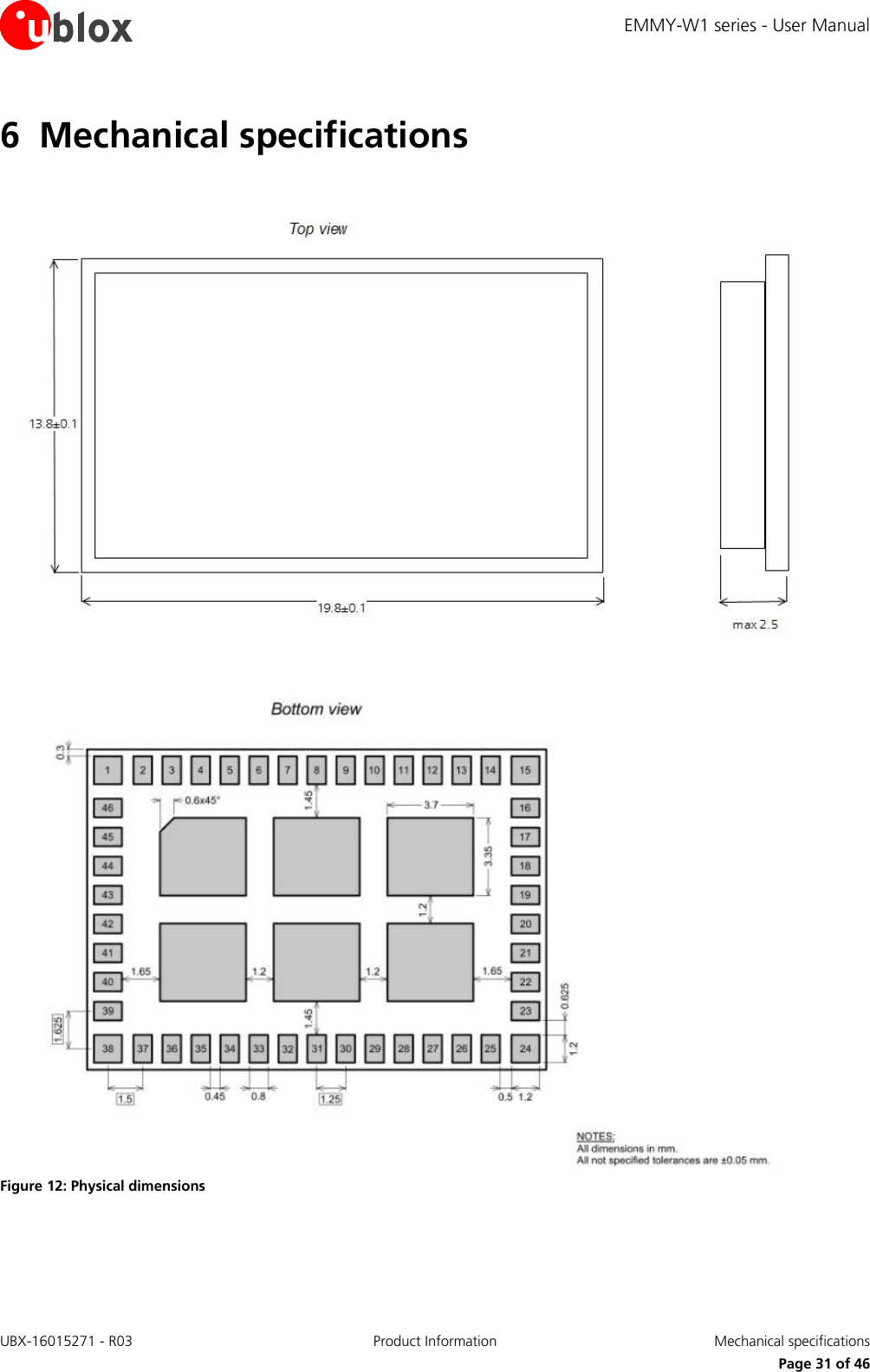
![EMMY-W1 series - User Manual UBX-16015271 - R03 Product Information Pin Definition Page 18 of 46 3 Pin Definition 3.1 Pin description Figure 11: Pin assignment No Pin name Pin type Supply domain Description 1 GND Ground - Ground 2 NC - Reserved, do not connect 3 NC - Reserved, do not connect 4 NC - Reserved, do not connect 5 GPIO_0 I/O VIO2 BT2HOST_WAKEUP (Output) 6 GPIO_1 I/O VIO2 WL2HOST_WAKEUP (Output) 7 GPIO_14 I/O VIO2 HOST2WL_WAKEUP (Input) 8 GPIO_15 I/O VIO2 HOST2BT_WAKEUP (Input) 9 GPIO_16 I/O VIO2 UART_LTE_SIN (Input) 10 GPIO_17 I/O VIO2 UART_LTE_SOUT (Output) 11 GPIO_4 I/O VIO2 PCM_DIN (Input) 12 GPIO_5 I/O VIO2 PCM_DOUT (Output) 13 GPIO_6 I/O VIO2 PCM_CLK (Input if slave, Output if master) 14 GPIO_7 I/O VIO2 PCM_SYNC (Input if slave, Output if master) 15 GND Ground - Ground 16 GND Ground - Ground 17 SD_CLK I VIO1 SDIO Clock input 18 SD_CMD I/O VIO1 SDIO Command line 19 SD_D0 I/O VIO1 SDIO Data line bit [0] 20 SD_D1 I/O VIO1 SDIO Data line bit [1] 21 SD_D2 I/O VIO1 SDIO Data line bit [2] 22 SD_D3 I/O VIO1 SDIO Data line bit [3] GNDEMMY-W1SD_CLKSD_CMDSD_D0SD_D1SD_D2SD_D3GNDGND3V3VIO1VIO2PDnGPIO_8GPIO_9GPIO_1029303125262728244645444342414039GNDANT2GNDGNDGNDGNDANT1GND654321GNDReservedReservedReservedGPIO_0GPIO_17GPIO_148GPIO_159GPIO_1610GPIO_1711GPIO_412GPIO_513GPIO_614GPIO_715GND1617181920212223GPIO_1132GPIO_333GPIO_234GND35NFC_ANT_N36NFC_ANT_P37GND38](https://usermanual.wiki/u-blox/EMMYW165.EMMY-W1-User-Manual/User-Guide-3172302-Page-18.png)
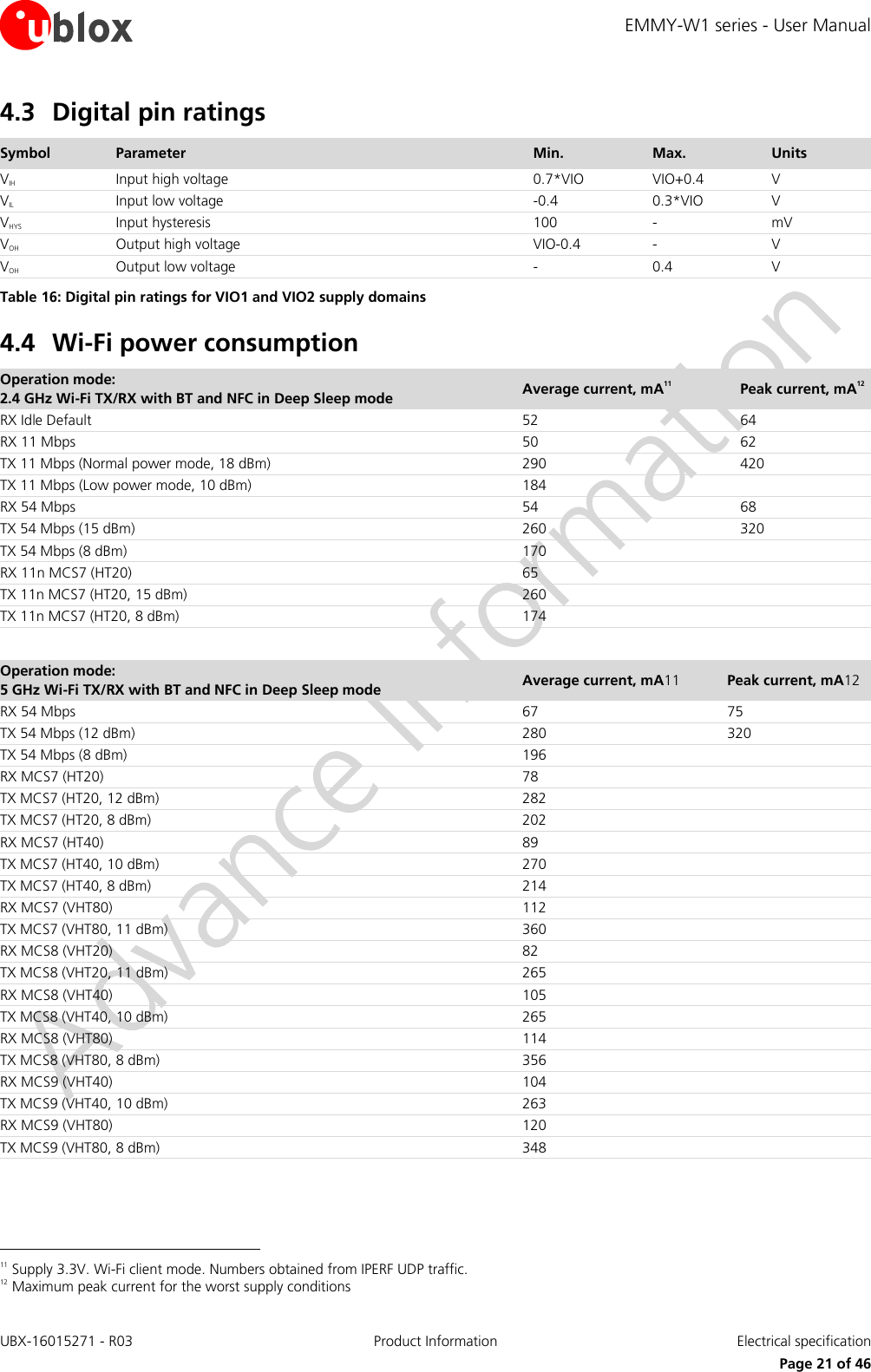
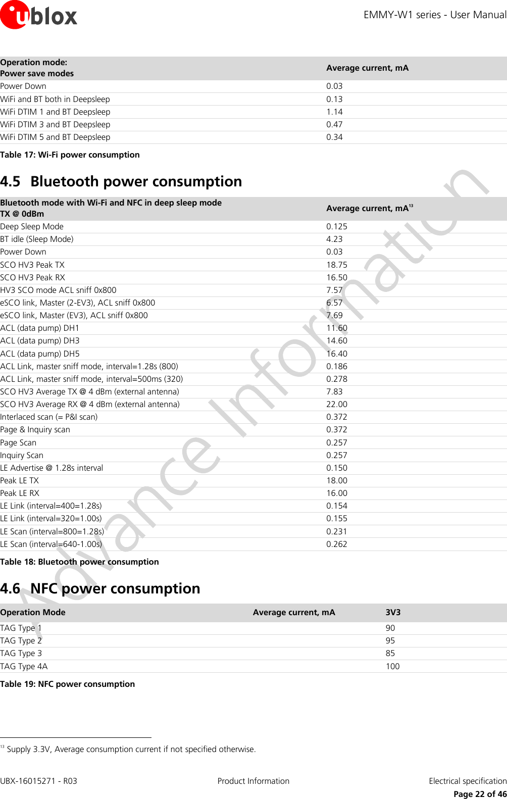
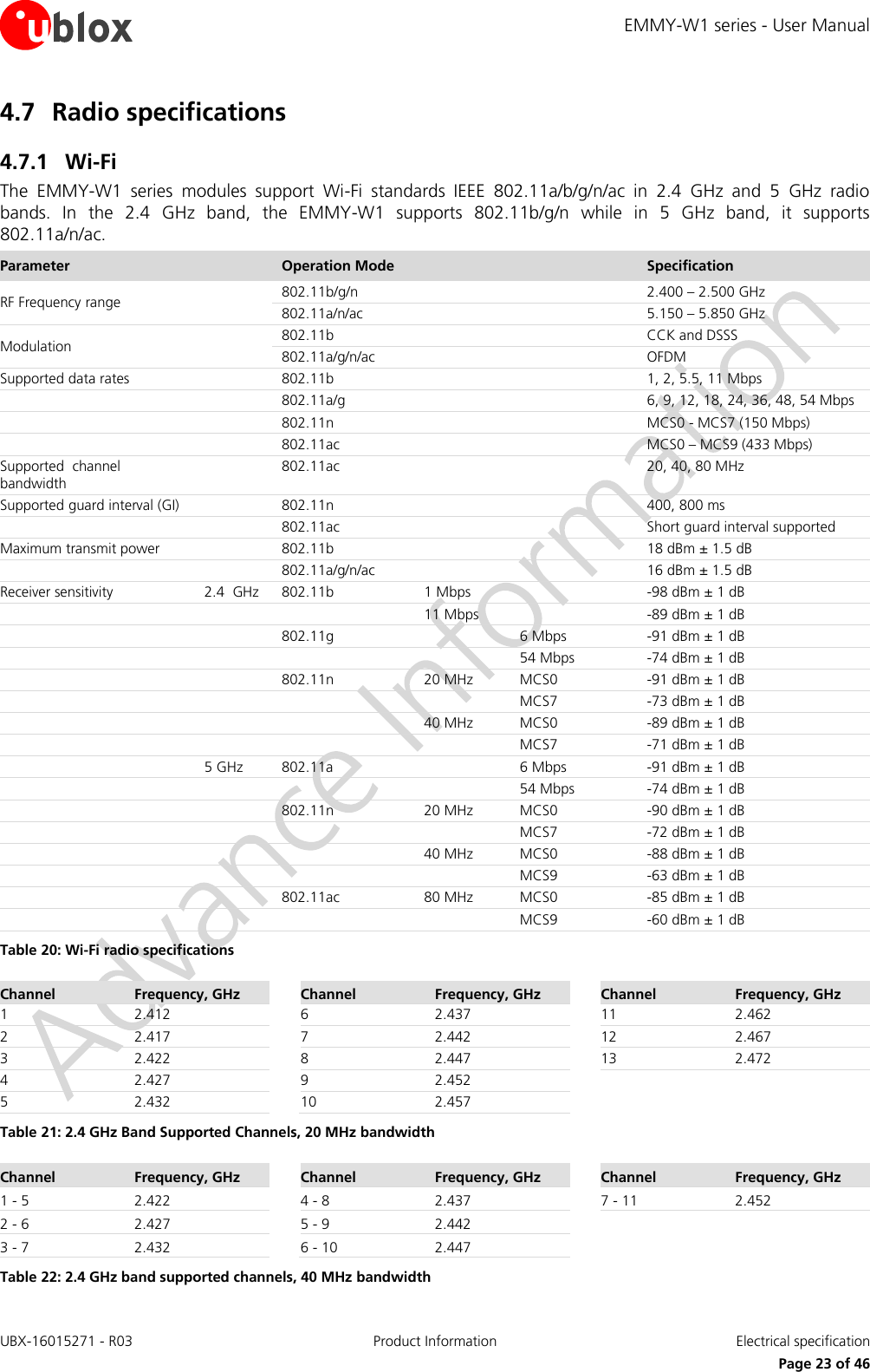
![EMMY-W1 series - User Manual UBX-16015271 - R03 Product Information Electrical specification Page 20 of 46 4 Electrical specification Stressing the device above one or more of the ratings listed in the Absolute Maximum Rating section may cause permanent damage. These are stress ratings only. Operating the module at these or at any conditions other than those specified in the Operating conditions section (section 4.2) of the specification should be avoided. Exposure to Absolute Maximum Rating conditions for extended periods may affect device reliability. Operating condition ranges define those limits within which the functionality of the device is guaranteed. Where application information is given, it is advisory only and does not form part of the specification. 4.1 Absolute maximum ratings Symbol Description Min. Typ Max. Units 3V3 Power supply voltage 3.3 V - 3.3 4.0 V VIO1 I/O supply voltage 1.8 V 1.8 2.2 V I/O supply voltage 3.3 V 3.3 4.0 V VIO2 I/O supply voltage 1.8 V - 1.8 2.2 V I/O supply voltage 3.3 V 3.3 4.0 V TSTORAGE Storage temperature -40 +85 ºC Table 13: Absolute maximum ratings The product is not protected against overvoltage or reversed voltages. If necessary, voltage spikes exceeding the power supply voltage specification given in table above must be limited to values within the specified boundaries by using appropriate protection devices. 4.2 Operating conditions Symbol Parameter Min. Typ Max. Units 3V3 Power supply voltage 3.3 V 2.97 3.3 3.63 V VIO1 I/O supply voltage 1.8V/3.3 V 1.62 1.8 1.98 V 2.97 3.3 3.63 V VIO2 I/O supply voltage 1.8V/3.3 V 1.62 1.8 1.98 V 2.97 3.3 3.63 V VDD_NFC NFC antenna input voltage (pins NFC_ANT_P/N) - - 3.6 V IANT_NFC NFC antenna peak input current (pins NFC_ANT_P/N)) - - 400 mA TA Ambient operating temperature -40 - +85 ºC Ripple Noise Peak-to-peak voltage ripple on 3V3, VIO1 or VIO2 supply line. The values have been determined in a frequency range from 10 KHz to > 2 MHz [3]. 20 - mV Table 14: Operating conditions Parameter Min. Typ Max. Units Storage temperature -40 +85 ºC Operation temperature -40 +85 ºC Table 15: Temperature range](https://usermanual.wiki/u-blox/EMMYW165.EMMY-W1-User-Manual/User-Guide-3172302-Page-20.png)
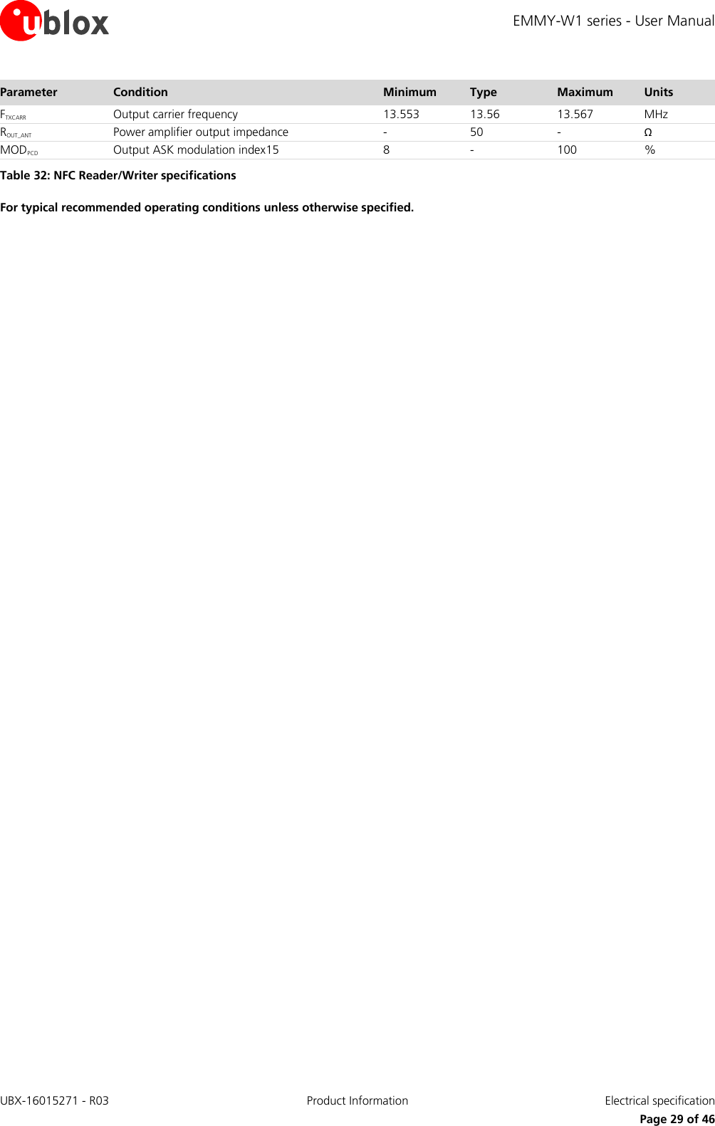
![EMMY-W1 series - User Manual UBX-16015271 - R03 Product Information Electrical specification Page 28 of 46 4.7.2 Bluetooth Parameter Specifications RF Frequency Range 2.400 – 2.4835 GHz Supported Modes Bluetooth v4.2 (including Bluetooth Low Energy and Classic Bluetooth with BR and EDR) Number of channels 79 Modulation 1 Mbps: GFSK (BR) 2 Mbps: π/4 DQPSK (EDR) 3 Mbps: 8DQPSK (EDR) Transmit Power Class 2, Class 1, BR: 10 dBm ± 2 dB, EDR: 8 dBm ± 2 dB14 Receiver Sensitivity -85 dBm Table 30: Bluetooth radio specifications 4.7.3 LTE co-existence Specific influence of BAW filters on the following RF parameters: Wi-Fi output power Wi-Fi sensitivity Bluetooth output power Bluetooth sensitivity Characterization of LTE co-existence: Maximum tolerated input power from LTE interferer Rejection in LTE bands Wi-Fi and Bluetooth desensitization in presence of LTE transmission in adjacent bands for given antenna isolation BAW decrease influence to LTE as well The BAW-Filter is included only in the EMMY-W161 module variant. 4.7.4 Near field communication 4.7.4.1 Card emulator specifications Parameter Condition Minimum Type Maximum Units AC characteristics VsensPICC Input carrier detection level, full-power mode, peak sinus differential voltage on NFC_ANT_P/N pin - 300 - mVpeak MODPICC Input ASK modulation index15 8 - 100 % DRPICC Input data rate (coding depending on standard: Manchester, Modified, Miller, or NRZ 106 - 848 Kbps Table 31: NFC card emulator For typical recommended operating conditions unless otherwise specified. 4.7.4.2 Reader/Writer specifications Parameter Condition Minimum Type Maximum Units DC characteristics VCMTX_PA Power amplifier output common mode level - VDDTX/2 - V AC characteristics 14 For regulatory reasons in Europe only class 2 operations are permitted. 15 As defined in ISO/IEC 14443-2, for example, [a-b]/[a+b] where a and b are the peak and minimum signal amplitude respectively.](https://usermanual.wiki/u-blox/EMMYW165.EMMY-W1-User-Manual/User-Guide-3172302-Page-28.png)
![EMMY-W1 series - User Manual UBX-16015271 - R03 Product Information Host drivers and firmware Page 30 of 46 5 Host drivers and firmware 5.1 General principle The EMMY-W1 series module does not contain any persistent software. A firmware binary will be downloaded by the host operating system driver on system start-up. 5.2 Supported operating systems 5.2.1 Linux Linux device drivers are available from u-blox. Once you sign the Limited Use License Agreement (LULA) with u-blox, a driver package will be available. This package includes: • Dedicated Kernel driver, to bind the Wi-Fi, Bluetooth and NFC block to the kernel. The sources of those drivers will be provided. • A dedicated firmware image, which will be uploaded during initialization. • Various configuration tools • Laboratory and manufacturing tools For a detailed description of the driver packages, refer to EMMY-W1 series System Integration Manual [3].](https://usermanual.wiki/u-blox/EMMYW165.EMMY-W1-User-Manual/User-Guide-3172302-Page-30.png)
![EMMY-W1 series - User Manual UBX-16015271 - R03 Product Information Qualification and approvals Page 33 of 46 If an end product allows the multiradio module to operate in the 5150-5350 MHz band (WLAN channel: 36-64), it is defined as class-2 radio equipment and must be marked accordingly. Class-2 radio equipment must have the "alert" sign affixed on the equipment, packaging and printed in the user manual. The EMMY-W1 multiradio module uses harmonized frequency bands thus it is comprised by subclass H01 of class 2 equipment, for which notification in accordance with article 6(4) of the R&TTE directive is not necessary. A definition of subclasses of Class 2 equipment can be found in the following link: http://ec.europa.eu/enterprise/sectors/rtte/files/rtte-subclass2_en.pdf The table below shows the restrictions when operating WLAN at different bands within the European countries Band Channel number Channel frequency [MHz] Indoor use allowed Outdoor use allowed Radio Equipment Class ISM 1 – 11 2412 – 2462 Yes Yes 1 U-NII 1 36 – 48 5180 – 5240 Yes No 2 U-NII 2 52 – 64 5260 – 5320 Yes No 2 U-NII 2e 100 – 140 5500 – 5700 Yes Yes 1 Table 33: Operating restrictions and radio equipment classification of EMMY-W1 series Guidance on how the end product is marked in accordance with the R&TTE directive can be found in the following links: http://ec.europa.eu/enterprise/sectors/rtte/documents/index_en.htm - h2-5 http://ec.europa.eu/enterprise/sectors/rtte/documents/guidance/index_en.htm A direct link to the quick guide to the marking requirements can be found here: http://ec.europa.eu/enterprise/sectors/rtte/files/guidance/guidance_en.pdf IMPORTANT: The ”CE” marking must be affixed to a visible location on the OEM product in which this module is installed and has to be labeled in accordance to R&TTE Directive 1999/5/EC. 7.1.2 FCC compliance The EMMY-W1 series module complies with Part 15 of the FCC Rules. Operation is subject to the following two conditions: 1. This device may not cause harmful interference, and 2. This device must accept any interference received, including interference that may cause undesired operation Non authorized modification could void authority to use this equipment. The internal / external antenna(s) used for this module must provide a separation distance of at least 20 cm from all persons and must not be co-located or operating in conjunction with any other antenna or transmitter. In accordance with 47 CFR § 15.19, the end product into which this module is integrated shall bear the following statement in a conspicuous location on the device: This device complies with Part 15 of the FCC Rules. Operation is subject to the following two conditions: 1. This device may not cause harmful interference, and 2. This device must accept any interference received, including interference that may cause undesired operation](https://usermanual.wiki/u-blox/EMMYW165.EMMY-W1-User-Manual/User-Guide-3172302-Page-33.png)
![EMMY-W1 series - User Manual UBX-16015271 - R03 Product Information Qualification and approvals Page 35 of 46 autorisé et l’impédance nécessaire pour chaque type d’antenne indiqué. Les types d’antenne ne figurant pas dans cette liste et ayant un gain supérieur au gain maximum indiqué pour ce type-là sont strictement interdits d’utilisation avec cet appareil. Le dispositif de fonctionnement dans la bande 5150-5250 MHz est réservé à une utilisation en intérieur pour réduire le risque d'interférences nuisibles à la co-canal systèmes mobiles par satellite Opération dans la bande 5600-5650 MHz n'est pas autorisée au Canada. Haute puissance radars sont désignés comme utilisateurs principaux (c.-àutilisateurs prioritaires) des bandes 5250-5350 MHz et 5650-5850 MHz et que ces radars pourraient causer des interférences et / ou des dommages à dispositifs LAN-EL. L’étiquette d’homologation d’Industrie Canada d’un module donné doit être posée sur l’appareil hôte à un endroit bien en vue en tout temps. En l’absence d’étiquette, l’appareil hôte doit porter une étiquette sur laquelle figure le numéro d’homologation du module d’Industrie Canada, précédé des mots « Contient un module d’émission », ou du mot « Contient », ou d’une formulation similaire allant dans le même sens et qui va comme suit : « Contient le module d’émission IC: (CN)-(UPN) », où (CN) représente le numéro de compagnie, attribué par Industrie Canada et (UPN) représente le numéro de produit unique attribué par le requérant. The approval of the variant EMMY-W165 with the IC: 8595A-EMMYW165 is still in progress and expected to be finished soon. The internal / external antenna(s) used for this module must provide a separation distance of at least 20 cm from all persons and must not be co-located or operating in conjunction with any other antenna or transmitter. See Table 34 for list of approved antennas. The approval type for all the EMMY-W1 series variants is a limited modular approval. Due to Industry Canada Modular Approval Requirements (Source: RSP-100 Issue 10), any application which includes the module must be approved by the module manufacturer (u-blox). The application manufacturer must provide design data for the review procedure. 7.2 Approved antennas For Bluetooth and Wi-Fi operation in the 2.4 GHz band and Wi-Fi operation in the 5 GHz band, the module has been tested and approved for use with the antenna listed in Table 34. Manufacturer Part Number Antenna type Peak gain [dBi] 2.4 GHz band 5 GHz band Antenova A10194 SMD chip antenna 10x10x0.9 [mm] [4] 1.8 4.1 Linx ANT-DB1-RAF-RPS Dual-band dipole antenna [5] 2.5 4.6 Taoglas GW.40.2153 Dual-band dipole antenna [6] 3.74 2.5 Taoglas GW.59.3153 Dual-band dipole antenna [7] 2.37 2.93 Walsin RFDPA870900SBLB8G1 Dual-band dipole antenna [8] 2 3 Linx ANT-2.4-CW-RCT-RP Single-band dipole antenna [9] 2.2 N/A Delock 88395 Dual-band dipole antenna [10] 1.5 2.1 Table 34: List of approved dual-band antennas The module can be integrated with other antennas which the OEM installer must authorize with respective regulatory agencies and after approval of the module manufacturer.](https://usermanual.wiki/u-blox/EMMYW165.EMMY-W1-User-Manual/User-Guide-3172302-Page-35.png)
![EMMY-W1 series - User Manual UBX-16015271 - R03 Product Information Qualification and approvals Page 36 of 46 7.2.1 Bluetooth antenna The following antennas are designated for Bluetooth transmission on EMMY-W163: Manufacturer Part Number Antenna type Peak gain [dBi] 2.4 GHz band Johanson Technology 2450AT45A100 SMD chip antenna 10x10x0.9 [mm] [11] 2.2 Taoglas GW.26.0151 Single-band monopole antenna [12] 0.0 Linx ANT-2.4-CW-RH Single-band monopole antenna [13] -0.9 Table 35: List of approved single-band antennas 7.2.2 NFC antenna The following antennas are designated to be used for Near Field Communication (NFC) on EMMY-W161, EMMY-W163 and EMMY-W165: Manufacturer Part Number Antenna type u-blox EMMY_NFC_ANT External PCB antenna with connector Table 36: List of approved NFC antenna 7.3 FCC and IC IDs (planned) Product name FCC ID IC ID EMMY-W161 XPYEMMYW161 8595A-EMMYW161 EMMY-W161-A XPYEMMYW161 8595A-EMMYW161 EMMY-W163 XPYEMMYW163 8595A-EMMYW163 EMMY-W163-A XPYEMMYW163 8595A-EMMYW163 EMMY-W165 XPYEMMYW165 8595A-EMMYW165 EMMY-W165-A XPYEMMYW165 8595A-EMMYW165 Table 37: FCC and IC IDs for different models of EMMY-W1 series 7.4 Certification in other countries Regulatory approvals for using the EMMY-W1 series module in Japan, South Korea, China, Taiwan and Australia are pending.](https://usermanual.wiki/u-blox/EMMYW165.EMMY-W1-User-Manual/User-Guide-3172302-Page-36.png)
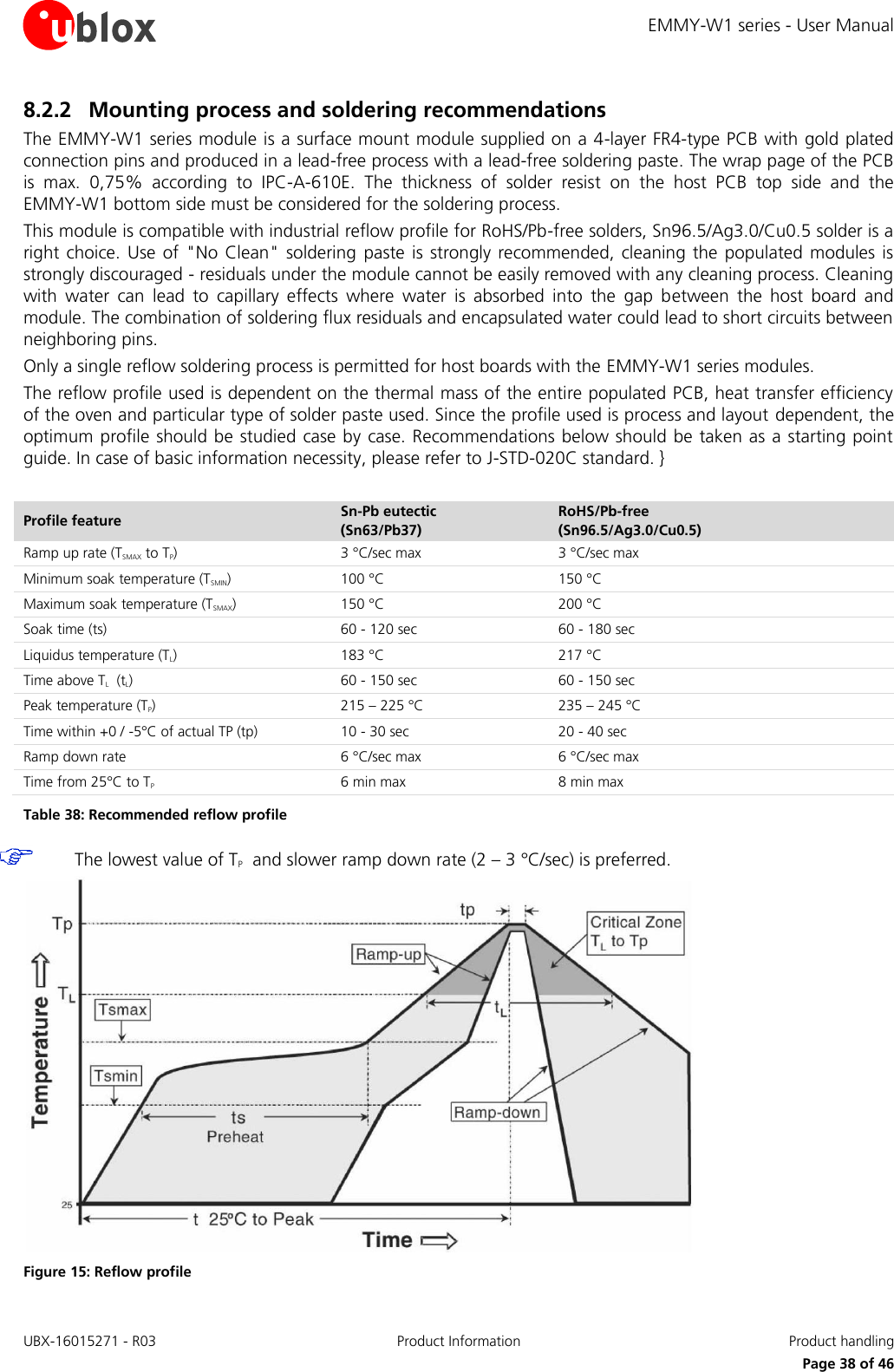
![EMMY-W1 series - User Manual UBX-16015271 - R03 Product Information Product handling Page 37 of 46 8 Product handling 8.1 Packaging The EMMY-W1 series modules are delivered as hermetically sealed tape and reels, to enable efficient production, production lot set-up and tear-down. For more information about packaging, see the u-blox Package Information Guide [1]. 8.1.1 Reels The EMMY-W1 series modules are deliverable in quantities of 500 pieces on a reel. The EMMY-W1 series modules are shipped on reel Type A as described in the u-blox Package Information Guide [1]. 8.1.2 Tapes The dimensions of the tapes are specified in Figure 14. Figure 14: EMMY-W1 Tape dimensions 8.2 Shipment, storage and handling For more information regarding shipment, storage and handling see the u-blox Package Information Guide [1]. 8.2.1 Moisture sensitivity levels The EMMY-W1 series modules are rated at moisture sensitivity level 3. See moisture sensitive warning label on each shipping bag for detailed information. After opening the dry pack, modules must be mounted within 168 hours in factory conditions of maximum 30°C/60%RH or must be stored at less than 10%RH. Modules require baking if the humidity indicator card shows more than 10% when read at 23±5°C or if the conditions mentioned above are not met. Please refer to J-STD-033B standard for bake procedure. }](https://usermanual.wiki/u-blox/EMMYW165.EMMY-W1-User-Manual/User-Guide-3172302-Page-37.png)
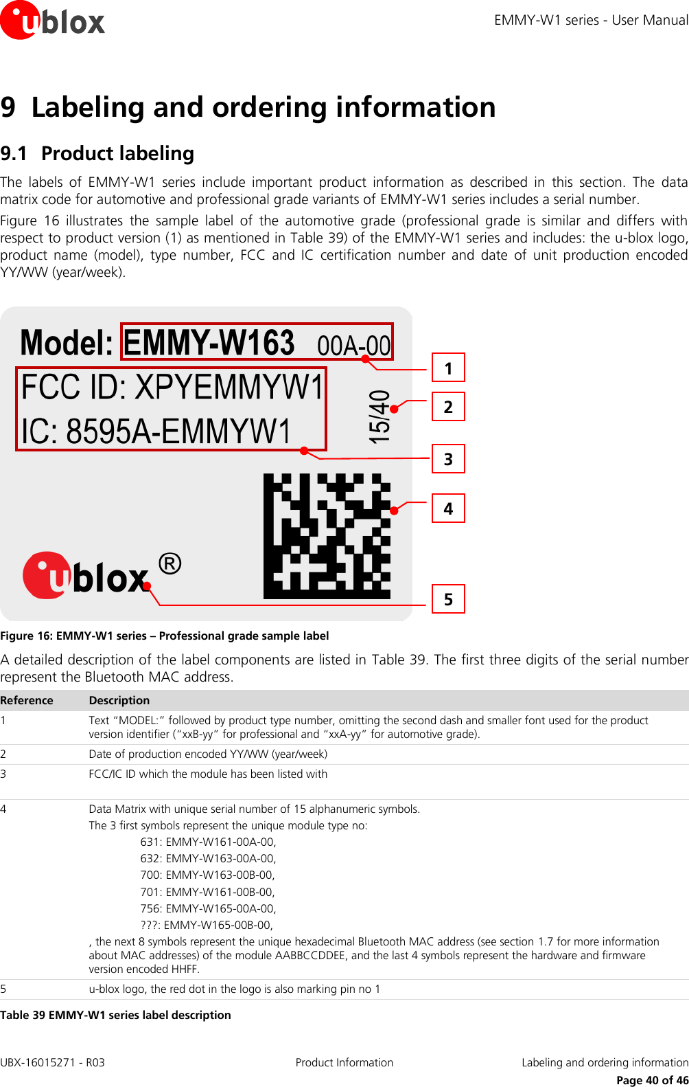
![EMMY-W1 series - User Manual UBX-16015271 - R03 Product Information Labeling and ordering information Page 41 of 46 9.2 Explanation of codes Two different product code formats are used. The Product Name is used in documentation such as this data sheet and identifies all u-blox products, independent of packaging and quality grade. The Ordering Code includes options and quality, while the Type Number includes the hardware and firmware versions. Table 40 below details these three different formats: Format Structure Product Name PPPP-TGVV Ordering Code PPPP-TGVV-TTQ Type Number PPPP-TGVV-TTQ-XX Table 40: Product code formats Table 41 explains the parts of the product code. Code Meaning Example PPPP Form factor EMMY TG Platform T – Dominant technology, For example, W: Wi-Fi, B: Bluetooth G - Generation W1 VV Variant based on the same platform; range [00…99] 61 TT Major Product Version 00 Q Quality grade A: Automotive B: Professional C: Standard A XX Minor product version (not relevant for certification) 00 Table 41: Part identification code 9.3 Ordering codes Ordering Code Product name Product EMMY-W161-00B EMMY-W161 EMMY-W161 professional grade module EMMY-W161-00A EMMY-W161-A EMMY-W161 automotive grade module EMMY-W163-00B EMMY-W163 EMMY-W163 professional grade module EMMY-W163-00A EMMY-W163-A EMMY-W163 automotive grade module EMMY-W165-00B EMMY-W165 EMMY-W165 professional grade module EMMY-W165-00A EMMY-W165-A EMMY-W165 automotive grade module EVK-EMMY-W161-A EVK-EMMY-W161 Evaluation kit for EMMY-W161 and EMMY-W161-A EVK-EMMY-W163-A EVK-EMMY-W163 Evaluation kit for EMMY-W163 and EMMY-W163-A Table 42: Product ordering codes Product changes affecting form, fit or function are documented by u-blox. For a list of Product Change Notifications (PCNs) see our website.](https://usermanual.wiki/u-blox/EMMYW165.EMMY-W1-User-Manual/User-Guide-3172302-Page-41.png)
![EMMY-W1 series - User Manual UBX-16015271 - R03 Product Information Related documents Page 44 of 46 Related documents [1] u-blox Package Information Guide, document number UBX-14001652 [2] Driver Software Application Note for ELLA-W1 series and EMMY-W1 series, document number UBX-15012542 [3] EMMY-W1 series System Integration Manual, document number UBX-15024929 [4] Mixtus A10194 Product Specification, Antenova-M2M, http://www.antenova-m2m.com/documents/download/40c67cf2e7a4c7b8cd0f7faed7f6d2ca4fe1886d597d5, October 2015 [5] ANT-DB1-RAF-xxx Data Sheet, Linx, http://www.linxtechnologies.com/resources/data-guides/ant-db1-raf-xxx.pdf, October 2015 [6] Specification. Part No.: GW.40.2153, taoglas, https://fccid.io/pdf.php?id=2415249, December 2015 [7] Specification. Part No.: GW.59.3153, taoglas, http://www.taoglas.com/images/product_images/original_images/GW.59.3153- 2.4GHz-5.8GHz Band Mount Dipole Antenna 080910.pdf, October 2015 [8] 2015 RF Devices and High Frequency Inductors Product catalog, http://www.passivecomponent.com/document/HF_Devices/2013RF_Catalogue.pdf, December 2015 [9] ANT-2.4-CW-RCT-xx Data Sheet, Linx, http://www.linxtechnologies.com/resources/data-guides/ant-2.4-cw-rct-xx.pdf, October 2015 [10] Delock WLAN 802.11 ac/a/b/g/n Antenna RP-SMA 2 dBi Omnidirectional Joint, 2015-11-26 http://www.delock.com/produkt/88395/pdf.html?sprache=en, November 2015 [11] 2.45 GHz High Gain SMD Chip Antenna P/N 2450AT45A100, Johanson Technology, http://www.johansontechnology.com/datasheets/antennas/2450AT45A100.pdf, October 2015 [12] 2.4 GHz Miniature Screw mount Monopole Antenna, taoglas, http://www.taoglas.com/images/product_images/original_images/GW.26.0112 2.4GHz Band Monopole SMA%28M%29RA.pdf, December 2015 [13] ANT-2.4-CW-RH Data Sheet, Linx, http://www.linxtechnologies.com/resources/data-guides/ant-2.4-cw-rh-xxx.pdf, December 2015 For regular updates to u-blox documentation and to receive product change notifications, register on our homepage (http://www.u-blox.ch/).](https://usermanual.wiki/u-blox/EMMYW165.EMMY-W1-User-Manual/User-Guide-3172302-Page-44.png)