testo Instruments 056001550 Digital manifold User Manual 0970 5501 en 06 V01 00
testo Instruments (Shenzhen) Co., Ltd Digital manifold 0970 5501 en 06 V01 00
UserManual.wiki
>
testo Instruments
>
056001550 User Manual
user manual
Navigation menu
Upload a User Manual
Namespaces
Wiki Guide
HTML
PDF
Info
Views
User Manual
Discussion / Help
Navigation
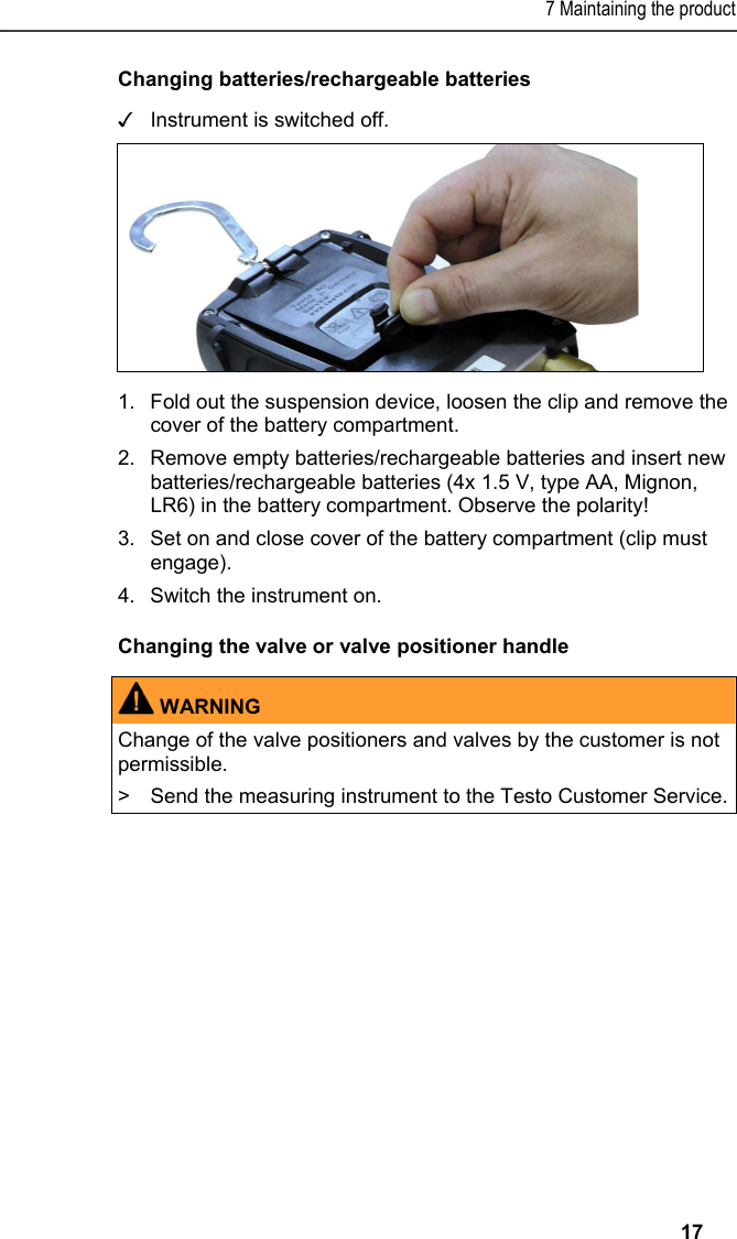
![2 Safety and the environment 4 2 Safety and the environment 2.1. About this document Use > Please read this documentation through carefully and familiarize yourself with the product before putting it to use. Pay particular attention to the safety instructions and warning advice in order to prevent injuries and damage to the products. > Keep this document to hand so that you can refer to it when necessary. > Hand this documentation on to any subsequent users of the product. Symbols and writing standards Representation Explanation Warning advice, risk level according to the signal word: Warning! Serious physical injury may occur. Caution! Slight physical injury or damage to the equipment may occur. > Implement the specified precautionary measures. Note: Basic or further information. 1....2.... Action: more steps, the sequence must be followed. > ... Action: a step or an optional step. - ... Result of an action. Menu Elements of the instrument, the instrument display or the program interface. [OK] Control keys of the instrument or buttons of the program interface. ... | ... Functions/paths within a menu. “...” Example entries](https://usermanual.wiki/testo-Instruments/056001550/User-Guide-2549744-Page-3.png)
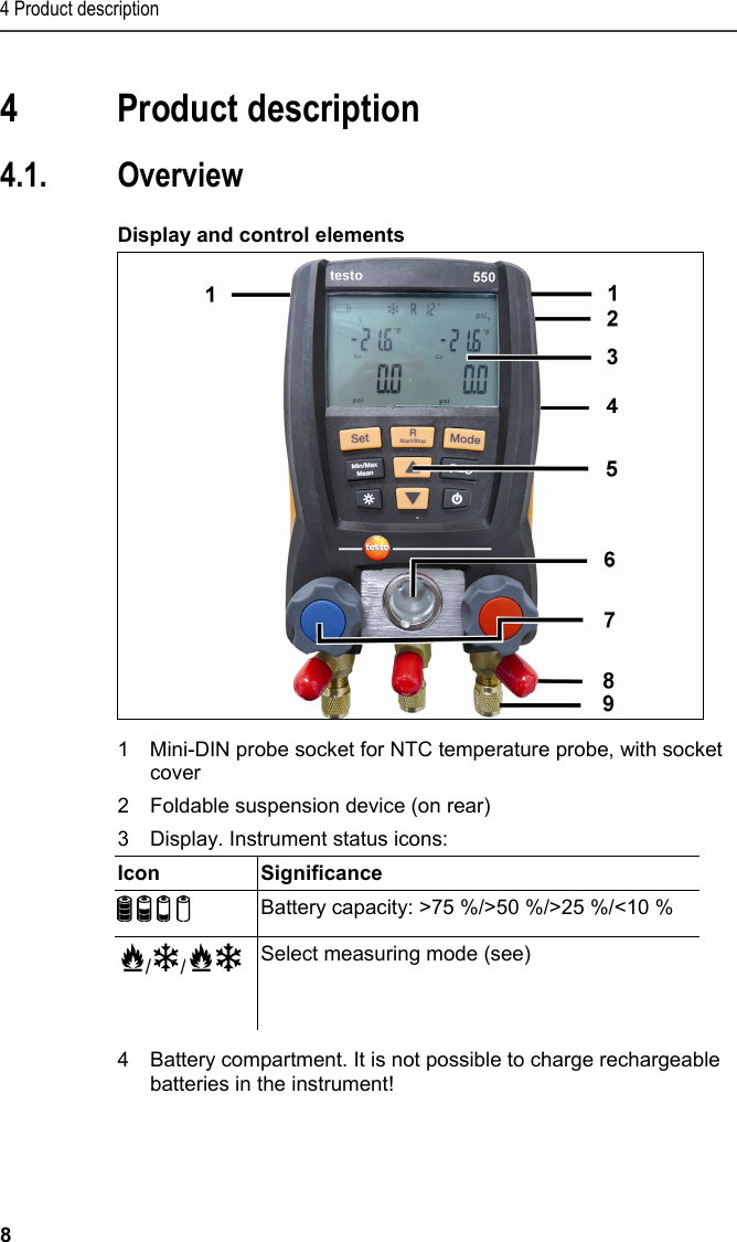
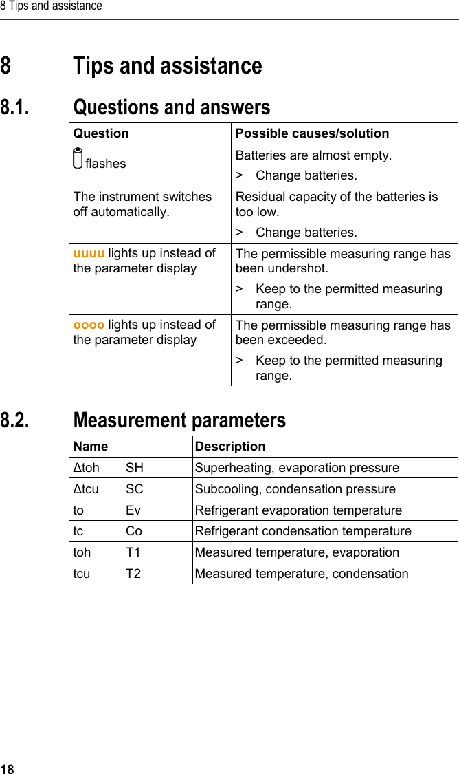
![5 First steps 9 5Control keys: Key Function [Set] Set units [R, Start/ Stop] Select refrigerant/ Start/stop / Tightness test [Mode] Switching measuring mode [Min/Max/Mean] Display min./max./mean values [▲] Up key: Change display view [p=0] Pressure zeroing Light key: Switch display light on/off [▼] Down key: Change display view [ ] Switching the instrument on/off 6Sight glass for refrigerant flow 72 x valve positioner 83 x hose parkers for refrigerant hoses 93 x connections 7/16" UNF, brass Left/right: Low pressure/high pressure, for refrigerant hoses with quick connect fitting, passage can be locked via valve positioner. Centre: for refrigerant bottles, for example, with sealing cap. 5 First steps Inserting batteries/rechargeable batteries 1.Fold out the suspension device and open the battery compartment (clip lock). 2.Insert batteries (included in delivery) or rechargeable batteries (4x 1.5 V, type AA/Mignon/LR6) in the battery compartment. Observe the polarity! 3.Close the battery compartment. When not in use for long period: Remove batteries/rechargeable batteries. Completely charge rechargeable batteries before using the instrument.](https://usermanual.wiki/testo-Instruments/056001550/User-Guide-2549744-Page-8.png)
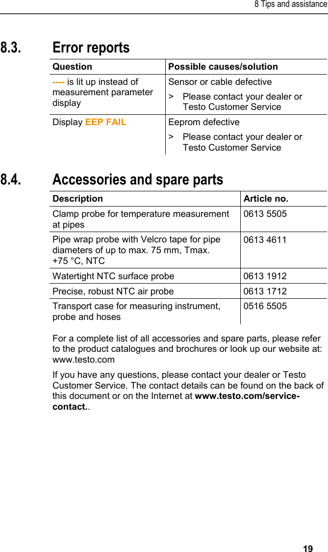
![5 First steps 10 Switching the instrument on > Press []. - Initialization phase: • All display segments are lit (length of time: 2 s). - Measurement view is opened. Performing settings 1.Press [Set]. - The configuration menu is opened and the adjustable parameter flashes. 2.Set parameters: Key functions Representation Explanation [▲] or [▼] Change parameter, select unit [Set] Select units/parameters Adjustable parameters Representation Explanation °C, °F Set temperature unit. bar, kPa, MPa, psi Set unit of pressure. Pabs, Prel or psia, psig Depending on the selected unit of pressure: Switch between absolute and relative pressure display. 29.92 inHg/ 1.013 bar Set current absolute pressure (see table) / / Select measuring mode (see Selecting the measuring mode, page 13) Settings will be applied following the final selection. Operating valve positioner The digital manifold acts like a conventional two-way manifold with regard to the refrigerant path: The passages are opened by opening the valves. The adjacent pressure is measured with valves closed as well as with them open. > Open valve: Turn valve positioner anticlockwise. > Close valve: Turn valve positioner clockwise.](https://usermanual.wiki/testo-Instruments/056001550/User-Guide-2549744-Page-9.png)
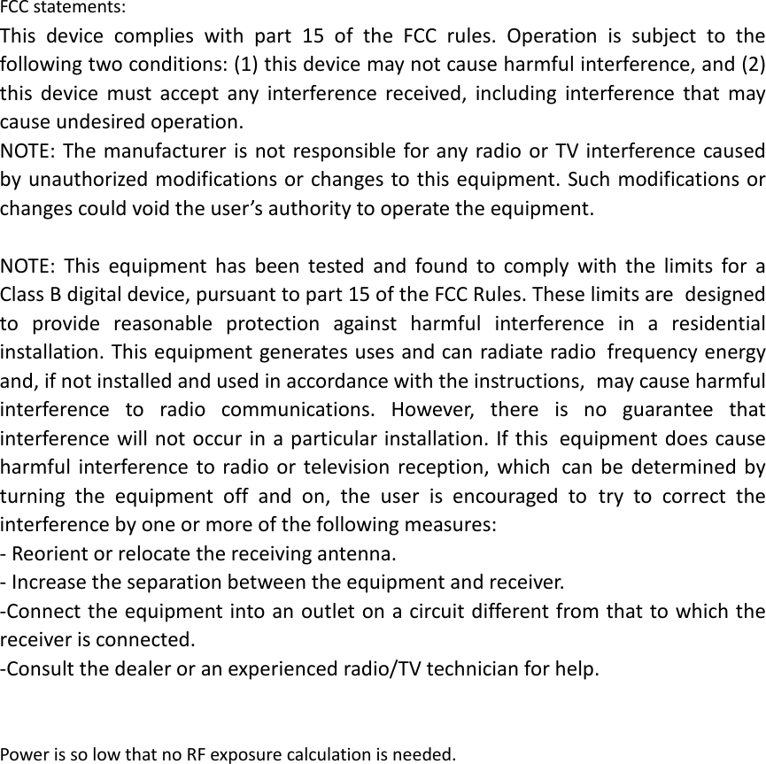
![6 Using the product 11 WARNING Only tighten valve positioner with your hand! Do not use any tools when tightening as otherwise the thread may be damaged. 6 Using the product 6.1. Preparing for measurement 6.1.1. Connecting the temperature sensor Sensors must be connected before the measuring instrument is switched on, so that they are recognised by the instrument. Surface temperature sensor An NTC temperature sensor (accessory) must be connected for measuring the pipe temperature and for automatic calculation of superheating and subcooling. Deactivating the surface compensation factor for insertion and air temperature sensor A surface compensation factor has been set in the measuring instrument to reduce the measuring errors in the main field of applications. This reduces measuring errors when using surface temperature sensors. If the measuring instrument testo 550 is used in combination with insertion or air temperature sensors (accessories), this factor must be deactivated: > Press and hold the keys SET + MODE together and switch on the measuring instrument []. - The instrument shows the message Fact off. The surface compensation factor becomes active every time the measuring instrument is switched on.](https://usermanual.wiki/testo-Instruments/056001550/User-Guide-2549744-Page-10.png)
![6 Using the product 12 6.1.2. Switching the instrument on > Press [ ]. Zeroing the pressure sensors Zero the pressure sensors before every measurement. ✓ All connections must be pressureless (ambient pressure). > Press key [P=0] and execute zeroing. Connecting the refrigerant hoses Before each measurement check whether the refrigerant hoses are in flawless condition. ✓ The valve actuators are closed. 1.Connect the refrigerant hoses for low-pressure side (blue) and high-pressure side (red) to the measuring instrument. 2.Connect the refrigerant hoses to the system. WARNINGThe measuring instrument dropping down or any other comparable mechanical load can cause breakage of the pipe pieces in the refrigerant hoses. The valve actuators may also suffer damage, which in turn could result in further damage inside the measuring instrument, which may not be detectable from outside. > For your own safety you should return the measuring instrument to the Testo Service for technical inspection. > You should therefore always replace the refrigerant hoses with new ones after the measuring instrument has dropped down or after any comparable mechanical loading. Setting the refrigerant 1.Press [R, Start/Stop]. - This opens the refrigerant menu and the currently selected refrigerant flashes. 2.Setting the refrigerant:](https://usermanual.wiki/testo-Instruments/056001550/User-Guide-2549744-Page-11.png)
![6 Using the product 13 Key functions Representation Explanation [▲] or [▼] Changing the refrigerant [R, Start/Stop] Confirm the setting and exit the refrigerant menu. Available refrigerants Representation Explanation R... Refrigerant number of refrigerant acc. to ISO 817 T... Special Testo designation for certain refrigerants (T8 = T1234yf) --- no refrigerant selected. Example: Setting refrigerant R401B 1.Press [▲] or [▼] several times, until R401B flashes. 2.Press [R, Start/Stop] to confirm the setting. Quitting the refrigerant selection > Press [R, Start/Stop] or automatically after 30 s, if no other key has been pressed. 6.1.3. Selecting the measuring mode 1.Press[Set] several times. 2.Select function with[▲] or [▼]. 3.Save setting: press [Set]. - Measuring mode is dsplayed. Display Mode Function Refrigeration system Normal functionality of the digital manifold Heat pump Normal functionality of the digital manifold Automatic mode If the automatic mode is activated, the testo 550 digital manifold automatically changes the display of the high and low pressure. This automatic change occurs when the pressure on the low-pressure side is 1 bar higher than the pressure on the high-pressure side. During the change, Load (2 s) is shown in the](https://usermanual.wiki/testo-Instruments/056001550/User-Guide-2549744-Page-12.png)
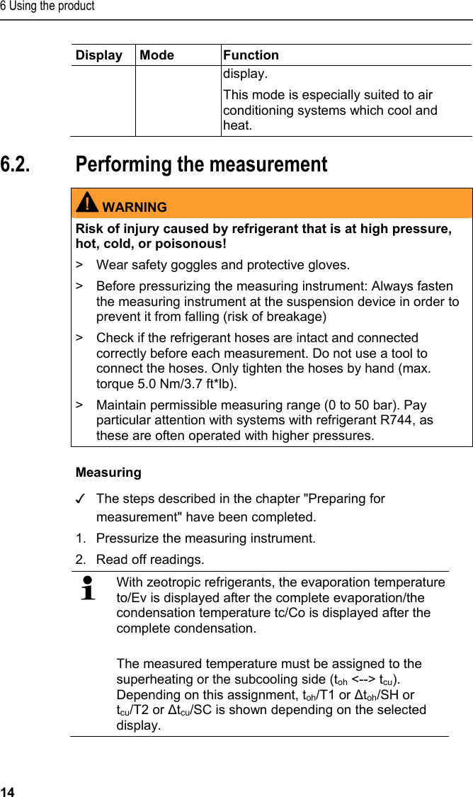
![6 Using the product 15 - Reading and display illumination flash: • 1 bar before reaching the critical pressure of the refrigerant, • upon exceeding the max. permissible pressure of 50 bar. Key functions > [▲] or [▼]: Change the reading display. Possible display combinations: Evaporation pressure Refrigerant evaporation temperature to/Ev Condensation pressure Refrigerant condensation temperature tc/Co or (only with connected temperature probe) Evaporation pressure Measured temperature toh/T1Condensation pressure Measured temperature tcu/T2 or (only with connected temperature probe) Evaporation pressure Superheating Δtoh/SH. Condensation pressure Subcooling Δtcu/SC With two connected NTC probes, Δt is also shown. > [Mean/Min/Max]: Record readings, display min./max. readings, mean values (since switching on). Tightness test/pressure drop test Systems can be tested for tightness with the temperature-compensated tightness test. The system pressure and the ambient temperature are measured over a defined period for this. A temperature probe can be connected that measures the ambient temperature for this (recommendation: NTC air probe, art. no. 0613 1712). Information about the temperature-compensated differential pressure and about the temperature at the beginning/end of the test exists as a result. If no temperature probe is connected, the tightness test can be performed without temperature compensation. ✓ The steps described in the chapter "Preparing for measurement" have been completed. 1.Press [Mode] (leakage test view). - Leakage test view is opened. ΔP is displayed. 2.Start the leakage test: Press [R, Start/Stop]. 3.End the leakage test: Press [R, Start/Stop].](https://usermanual.wiki/testo-Instruments/056001550/User-Guide-2549744-Page-14.png)
![7 Maintaining the product 16 - Result is displayed. 4. Confirm message: Press [Mode]. - You automatically jump to the evacuation/vacuum display menu. Evacuation/vacuum display The measurement is performed on the low-pressure side. 5. Press [Mode]. - Result is displayed on the low-pressure side. 6. Press [Mode]. - The measuring mode is displayed. 7 Maintaining the product Cleaning the instrument > If the housing of the instrument is dirty, clean it with a damp cloth. Do not use any aggressive cleaning agents or solvents! Weak household cleaning agents and soap suds may be used. Keeping connections clean > Keep screw connections clean and free of grease and other deposits, clean with a moist cloth as required. Removing oil residues > Carefully blow out oil residues in valve block using compressed air. Ensuring the measuring accuracy Testo Customer Service would be glad to further assist you if you so wish. > Check instrument regularly for leaks (recommended: annually). Keep to the permissible pressure range! > Calibrate instrument regularly (recommended: annually).](https://usermanual.wiki/testo-Instruments/056001550/User-Guide-2549744-Page-15.png)