ZyXEL Communications P660NT1A 802.11n Wireless ADSL2+ Gateway User Manual SMG 700 User s Guide V1 00 Nov 2004
ZyXEL Communications Corporation 802.11n Wireless ADSL2+ Gateway SMG 700 User s Guide V1 00 Nov 2004
Contents
- 1. user manual 1
- 2. user manual 2
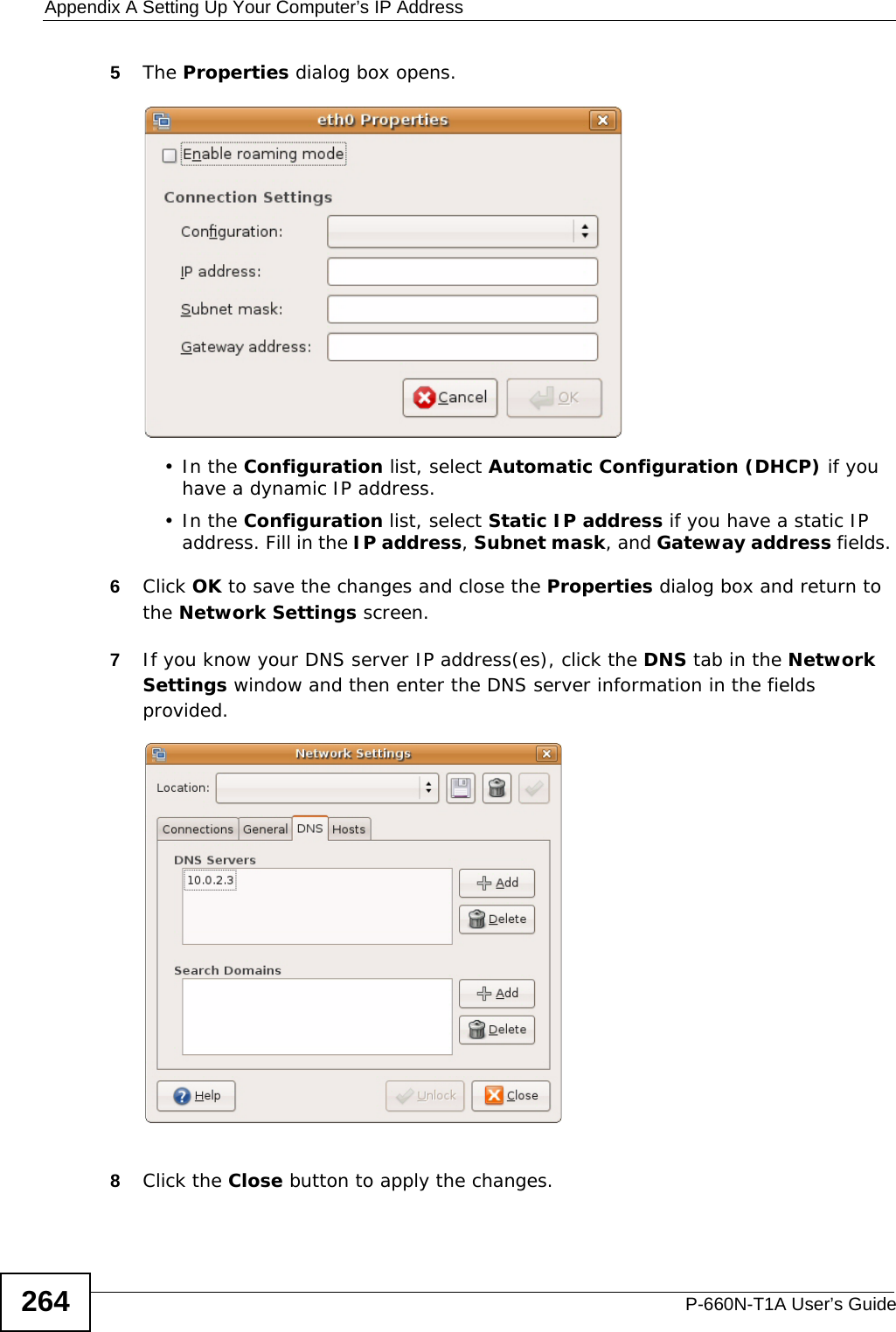
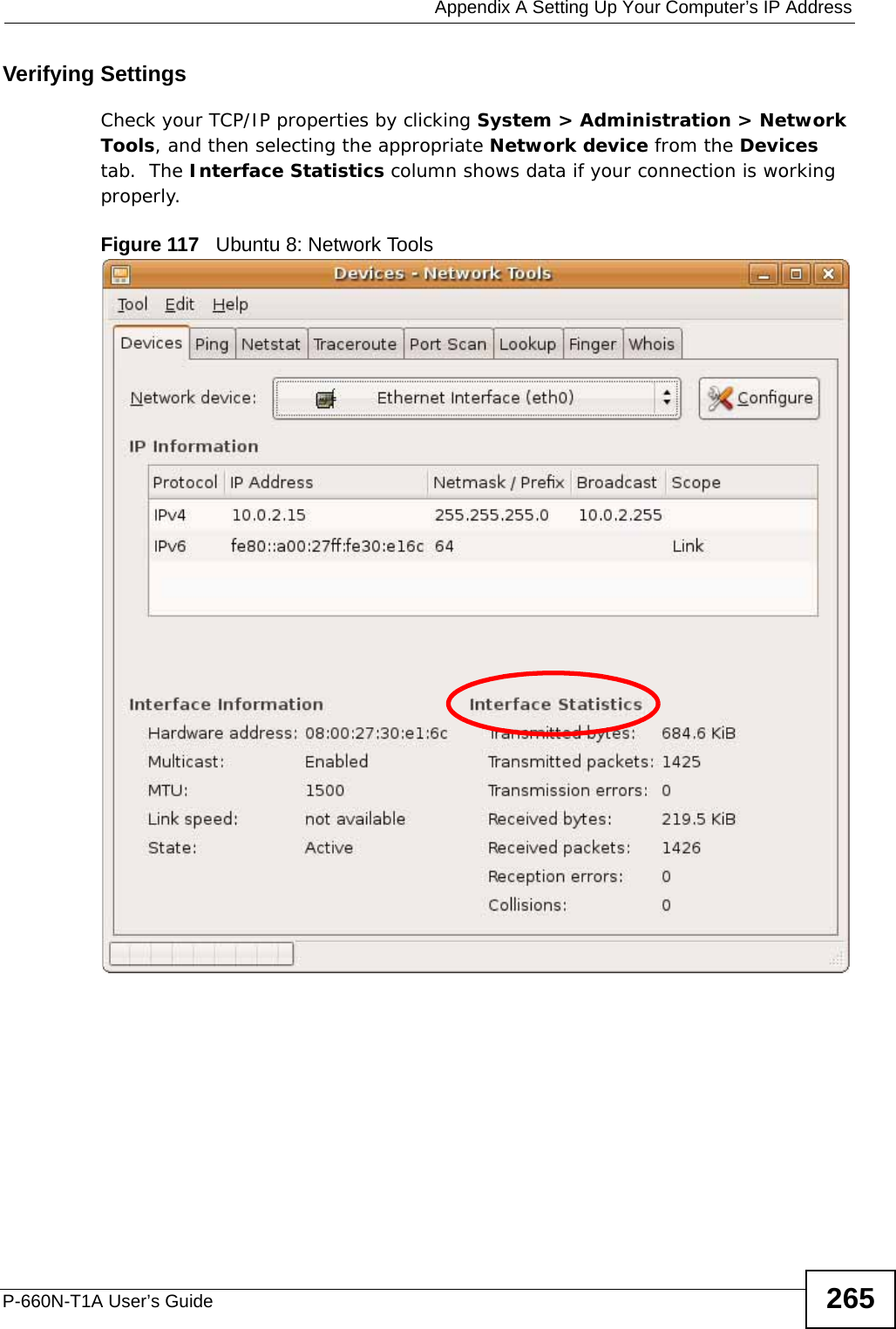
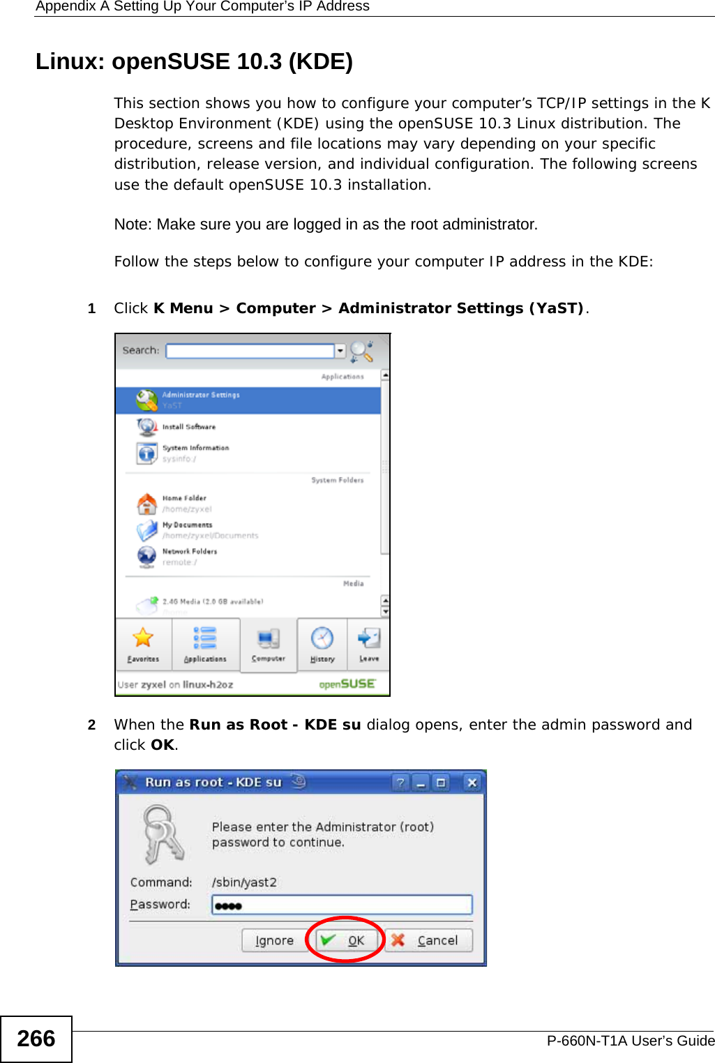
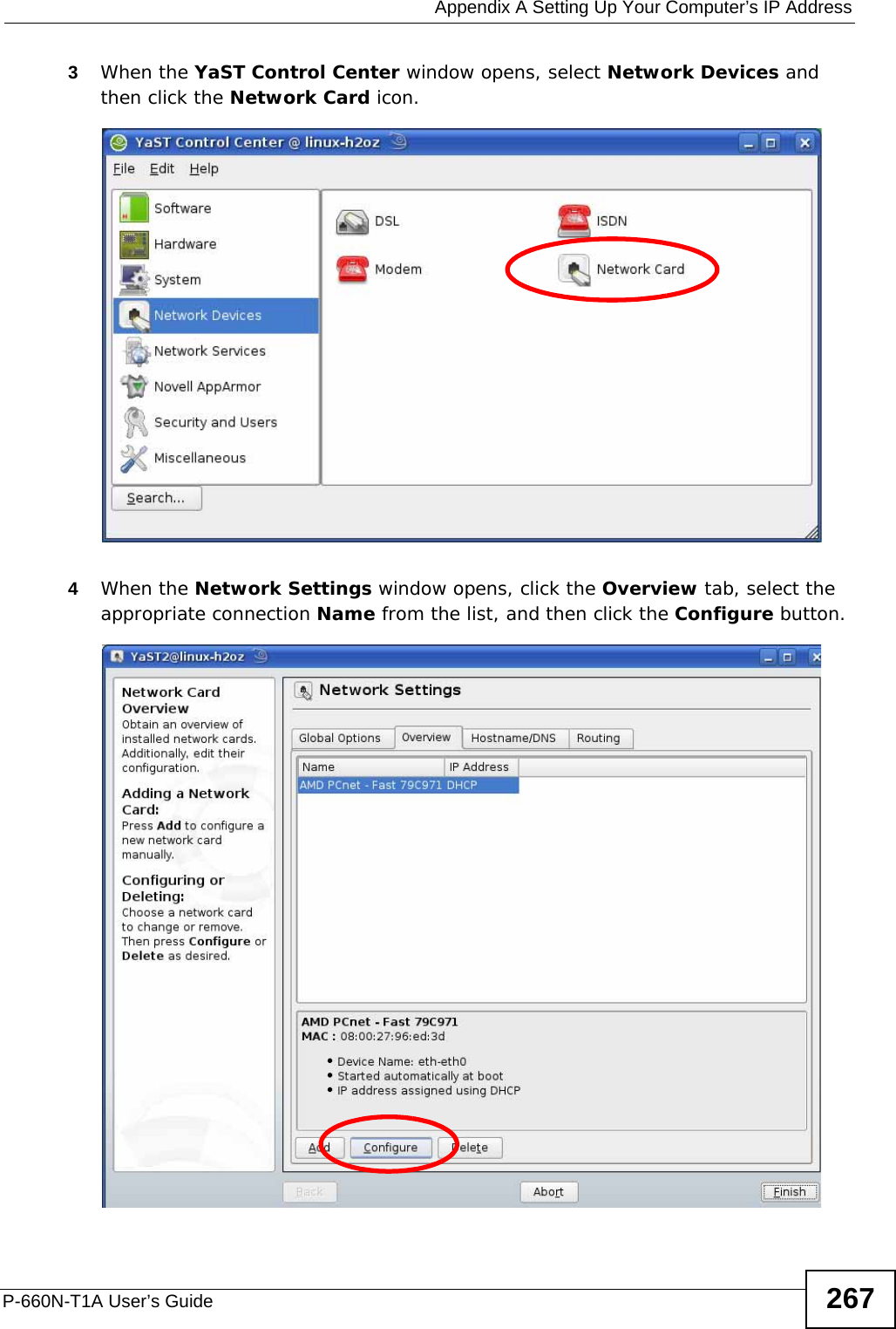
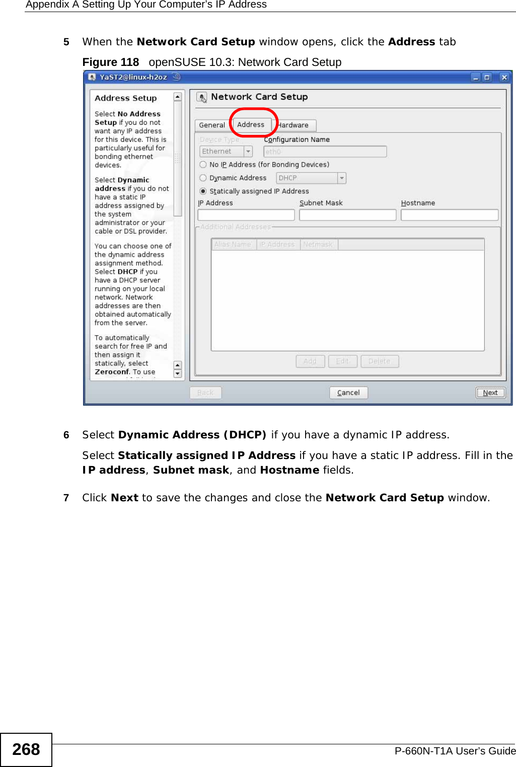
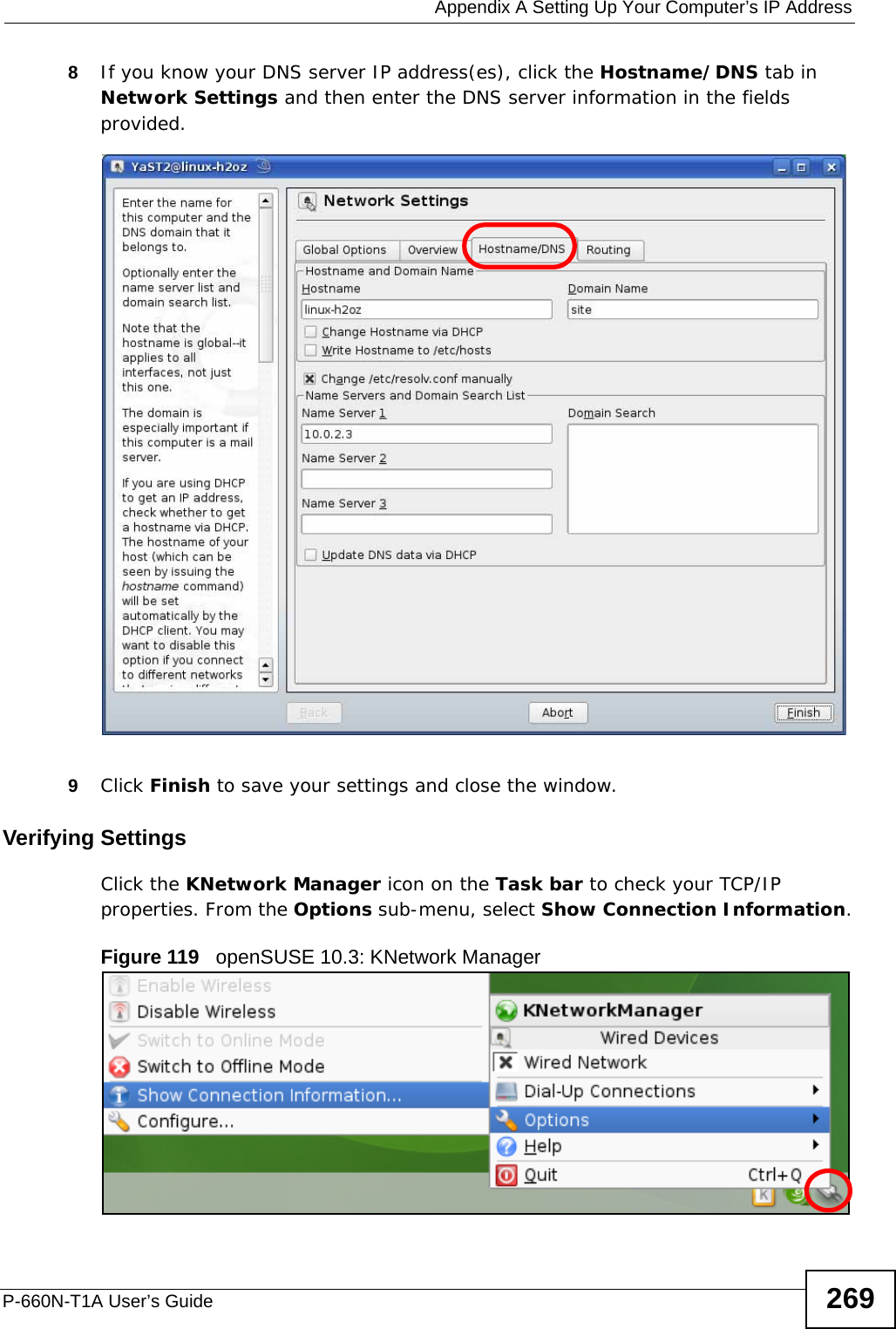
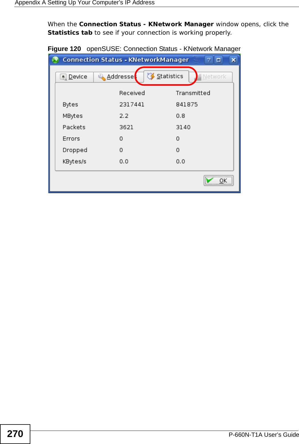
user manual 2

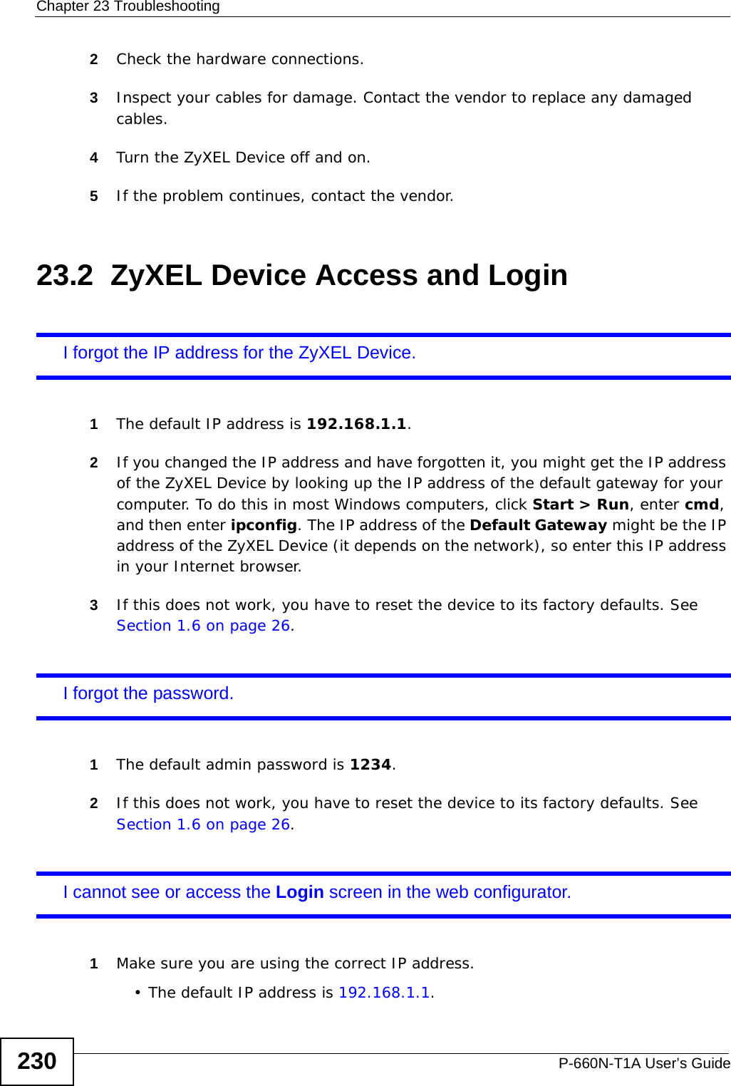
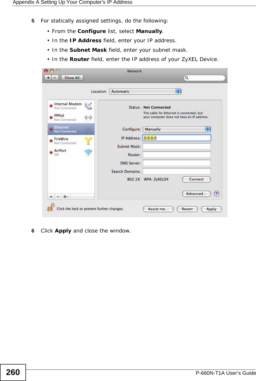
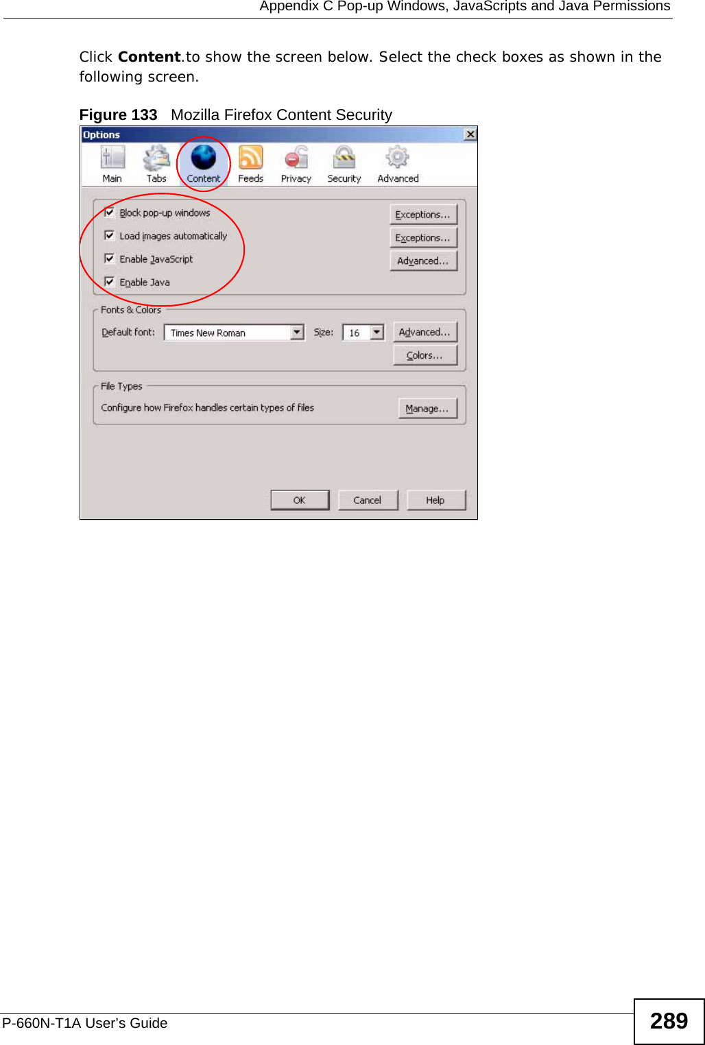
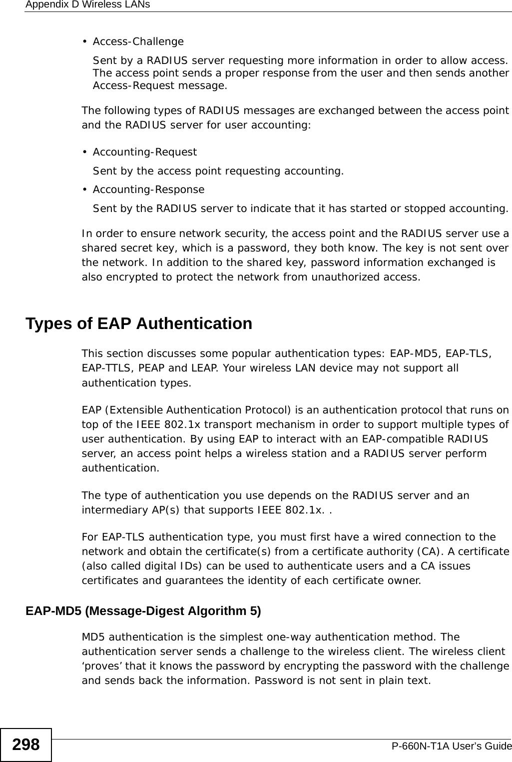
![Chapter 23 TroubleshootingP-660N-T1A User’s Guide 231• If you changed the IP address (Section 7.2 on page 87), use the new IP address.• If you changed the IP address and have forgotten it, see the troubleshooting suggestions for I forgot the IP address for the ZyXEL Device.2Check the hardware connections, and make sure the LEDs are behaving as expected. See the Quick Start Guide.3Make sure your Internet browser does not block pop-up windows and has JavaScripts and Java enabled. See Appendix C on page 281.4Make sure your computer is in the same subnet as the ZyXEL Device. (If there are routers between your computer and the ZyXEL Device, skip this step.)• If there is a DHCP server on your network, make sure your computer is using a dynamic IP address. See Appendix A on page 243. Your ZyXEL Device is a DHCP server by default.• If there is no DHCP server on your network, make sure your computer’s IP address is in the same subnet as the ZyXEL Device. See Appendix A on page 243.5Reset the device to its factory defaults, and try to access the ZyXEL Device with the default IP address. See Section 1.6 on page 26.6If the problem continues, contact the network administrator or vendor, or try one of the advanced suggestions.Advanced Suggestions• Try to access the ZyXEL Device using another service, such as Telnet. If you can access the ZyXEL Device, check the remote management settings and firewall rules to find out why the ZyXEL Device does not respond to HTTP. • If your computer is connected to the WAN port or is connected wirelessly, use a computer that is connected to a ETHERNET port.I can see the Login screen, but I cannot log in to the ZyXEL Device.1Make sure you have entered the password correctly. The default admin password is 1234. The field is case-sensitive, so make sure [Caps Lock] is not on. 2You cannot log in to the web configurator while someone is using Telnet to access the ZyXEL Device. Log out of the ZyXEL Device in the other session, or ask the person who is logged in to log out. 3Turn the ZyXEL Device off and on.](https://usermanual.wiki/ZyXEL-Communications/P660NT1A.user-manual-2/User-Guide-1315612-Page-11.png)
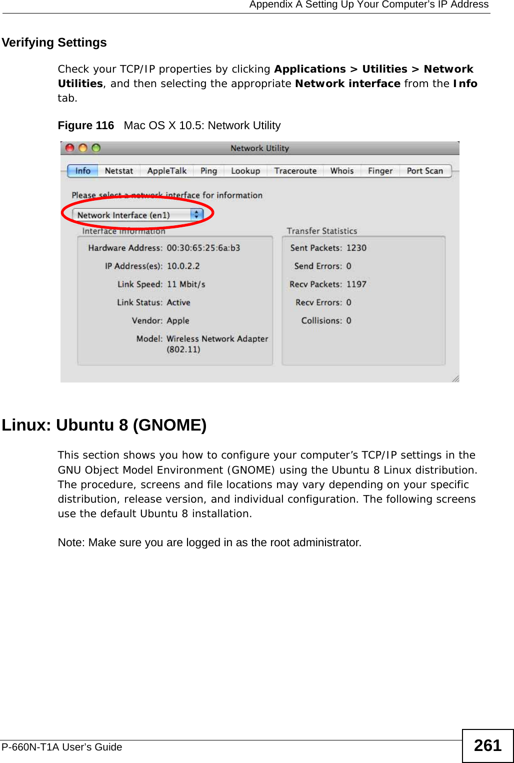
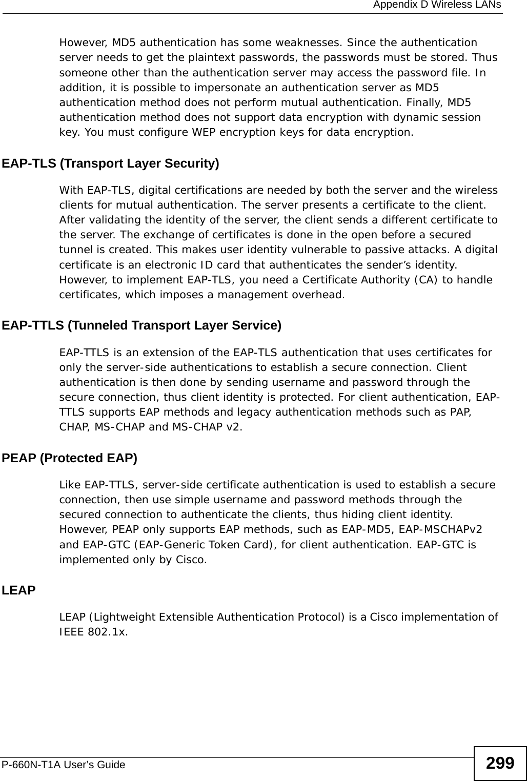
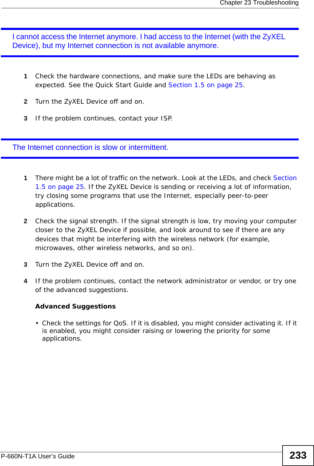
![Chapter 23 TroubleshootingP-660N-T1A User’s Guide2324If this does not work, you have to reset the device to its factory defaults. See Section 23.1 on page 229.I cannot Telnet to the ZyXEL Device.See the troubleshooting suggestions for I cannot see or access the Login screen in the web configurator. Ignore the suggestions about your browser.I cannot use FTP to upload / download the configuration file. / I cannot use FTP to upload new firmware.See the troubleshooting suggestions for I cannot see or access the Login screen in the web configurator. Ignore the suggestions about your browser.23.3 Internet AccessI cannot access the Internet.1Check the hardware connections, and make sure the LEDs are behaving as expected. See the Quick Start Guide and Section 1.5 on page 25.2Make sure you entered your ISP account information correctly in the wizard. These fields are case-sensitive, so make sure [Caps Lock] is not on. 3If you are trying to access the Internet wirelessly, make sure the wireless settings in the wireless client are the same as the settings in the AP.4If you are trying to access the Internet wirelessly, make sure you enabled the wireless LAN and have selected the correct country and channel in which your ZyXEL Device operates in the Wireless LAN > AP screen.5Disconnect all the cables from your device, and follow the directions in the Quick Start Guide again. 6If the problem continues, contact your ISP.](https://usermanual.wiki/ZyXEL-Communications/P660NT1A.user-manual-2/User-Guide-1315612-Page-12.png)

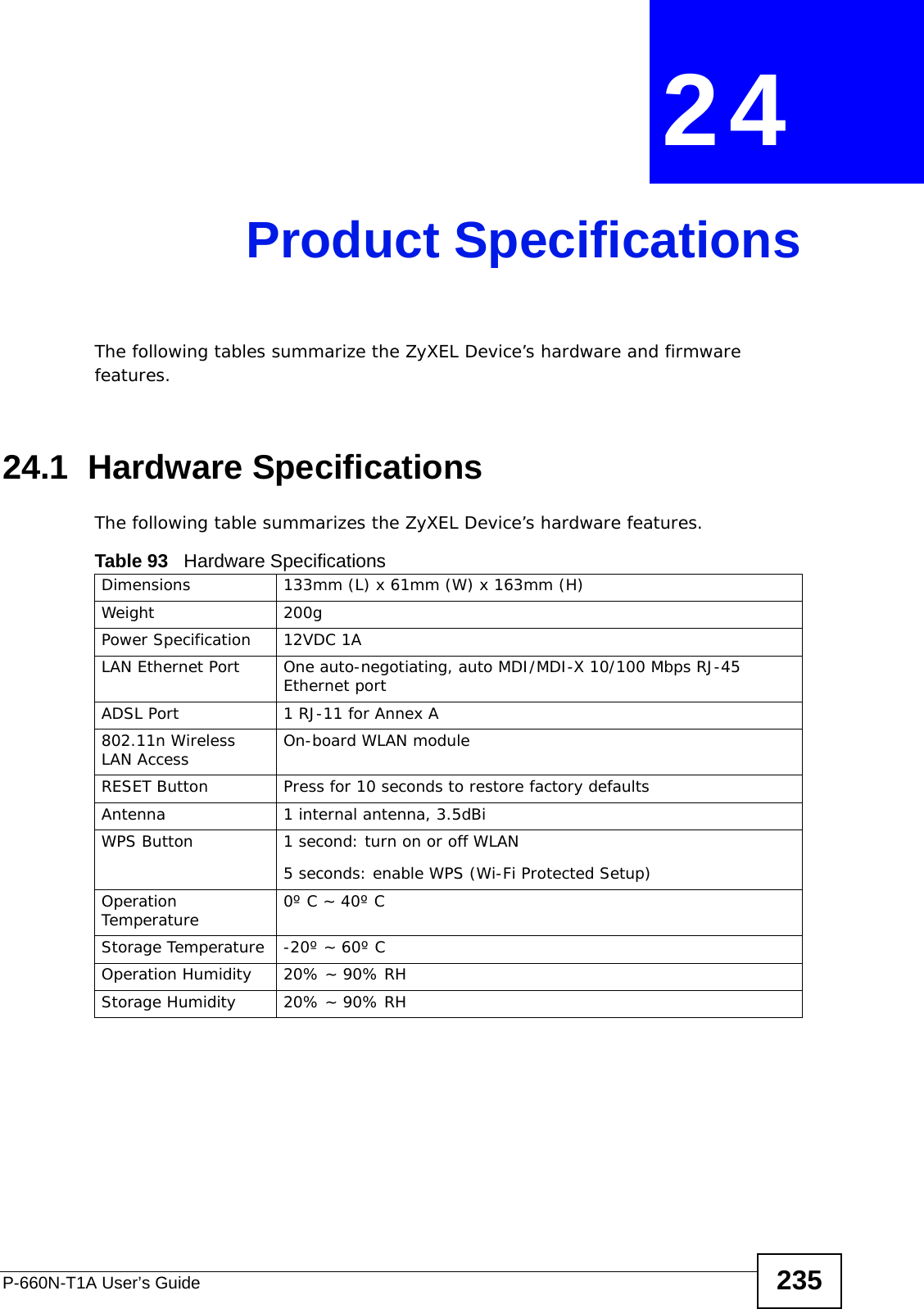
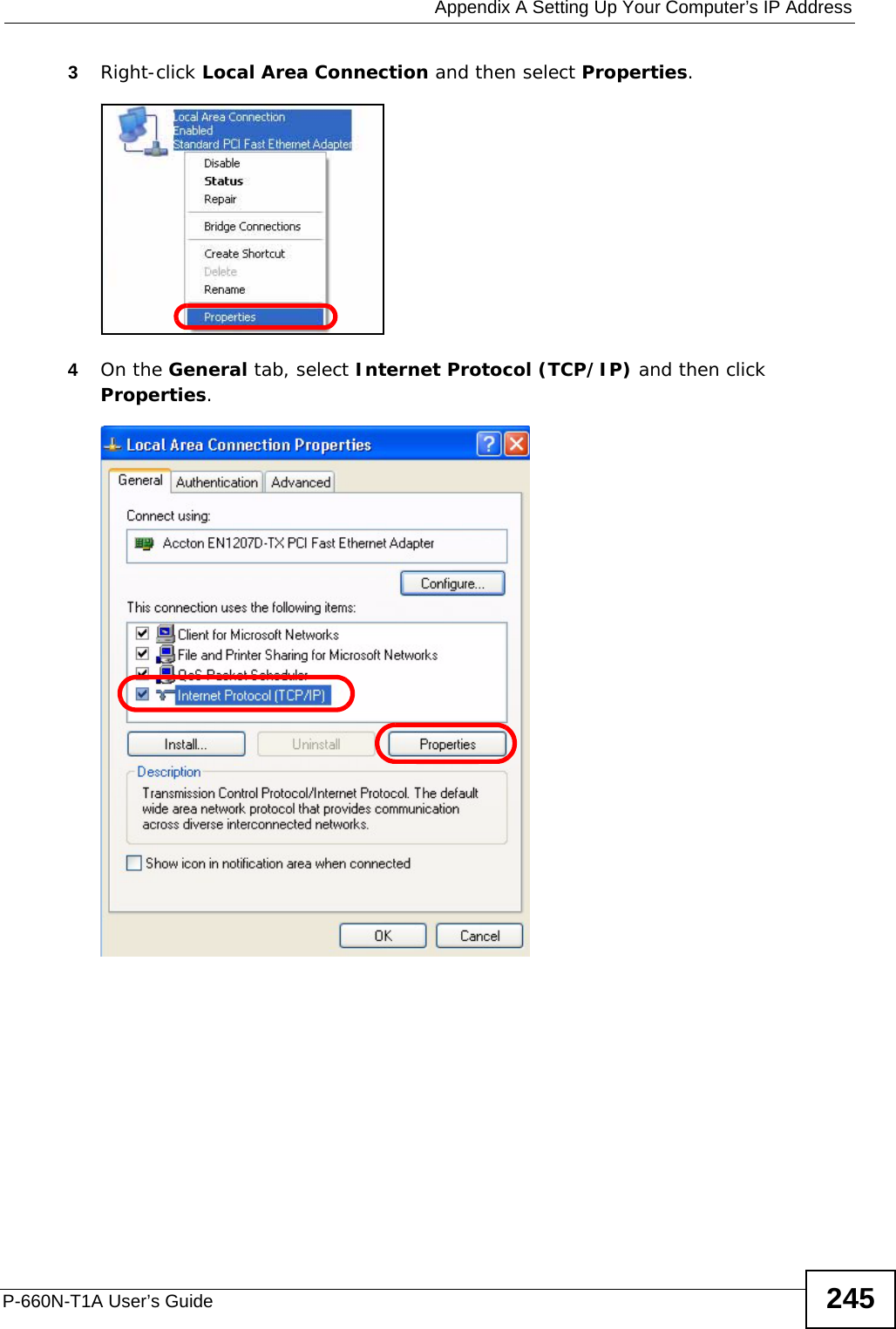
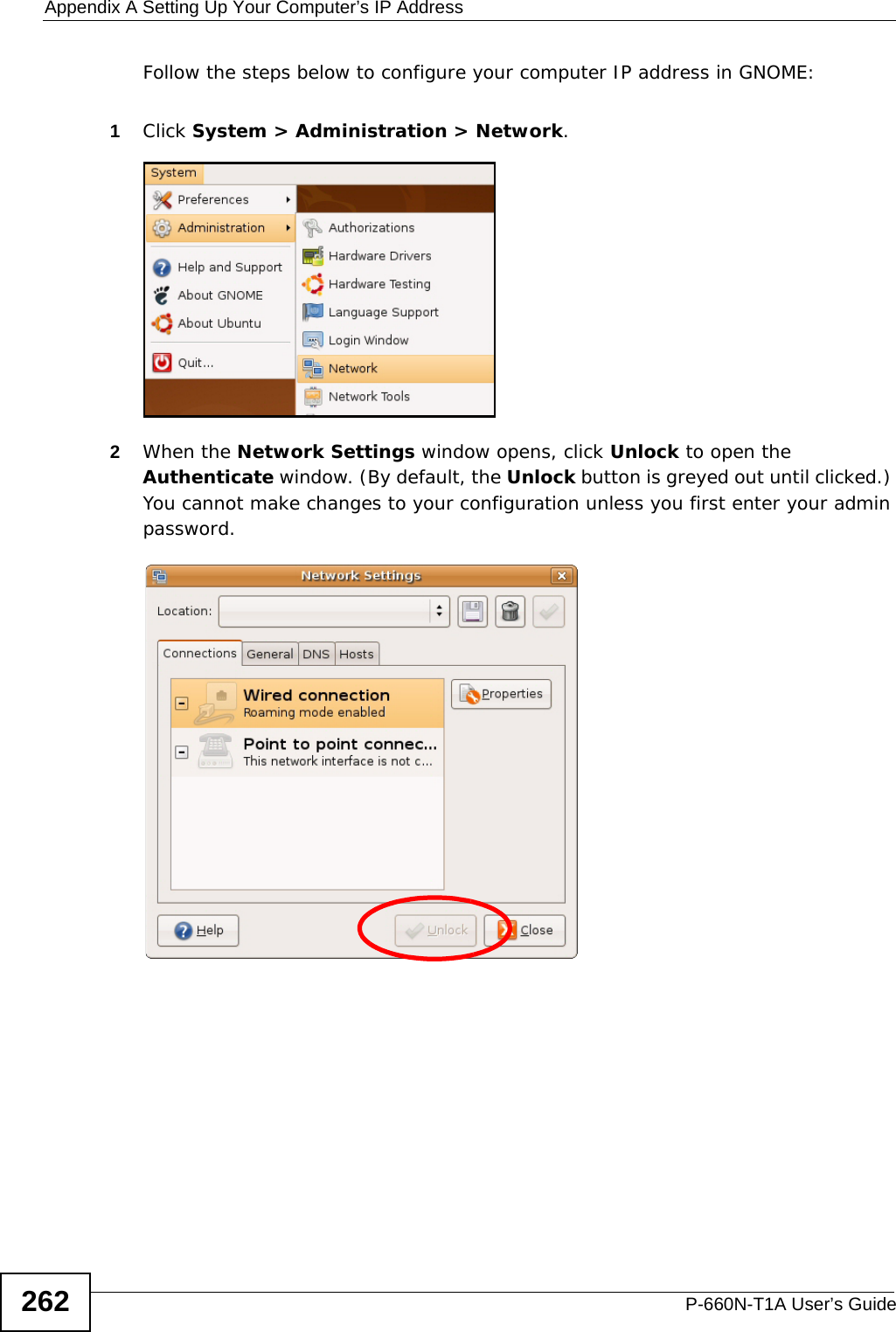
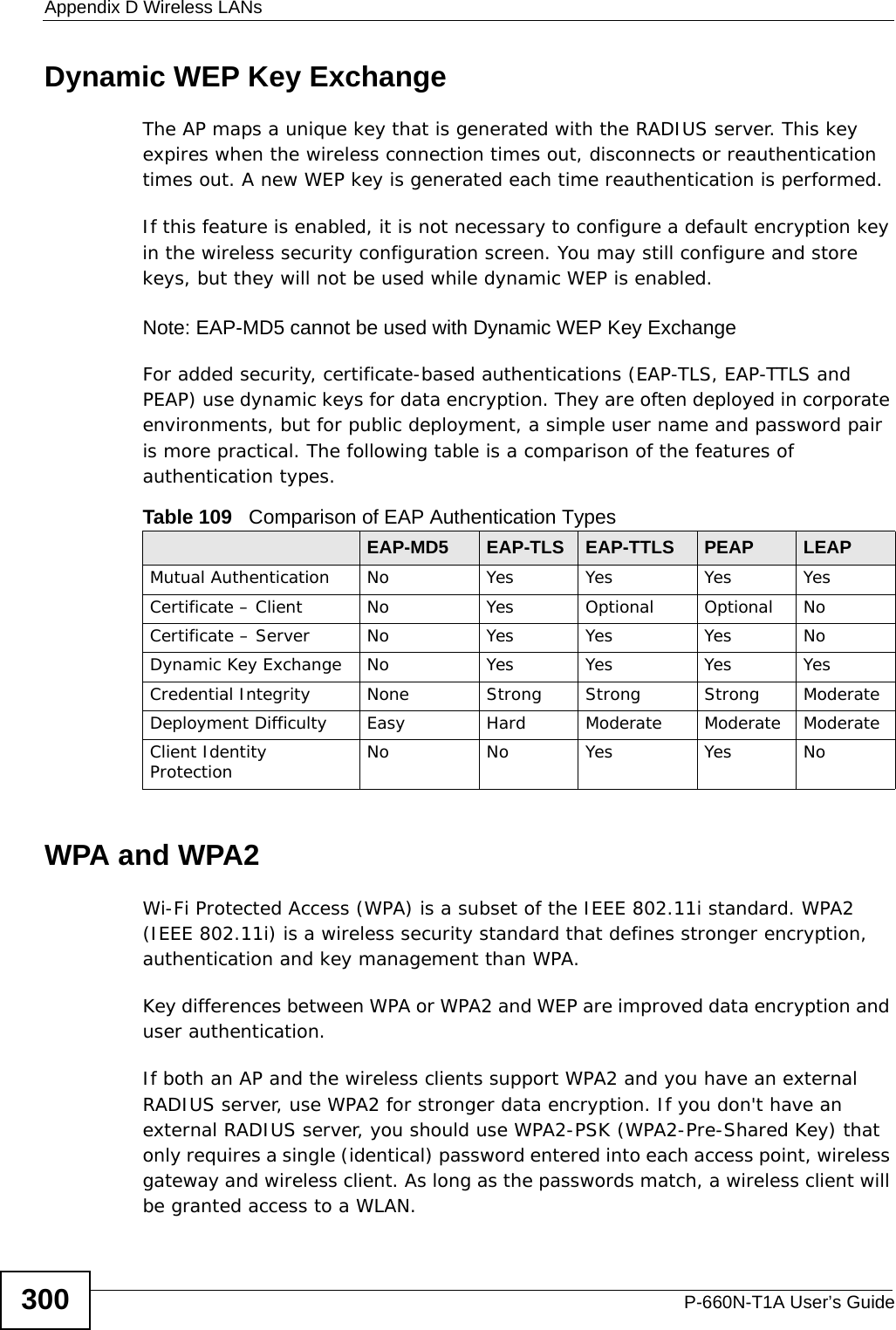
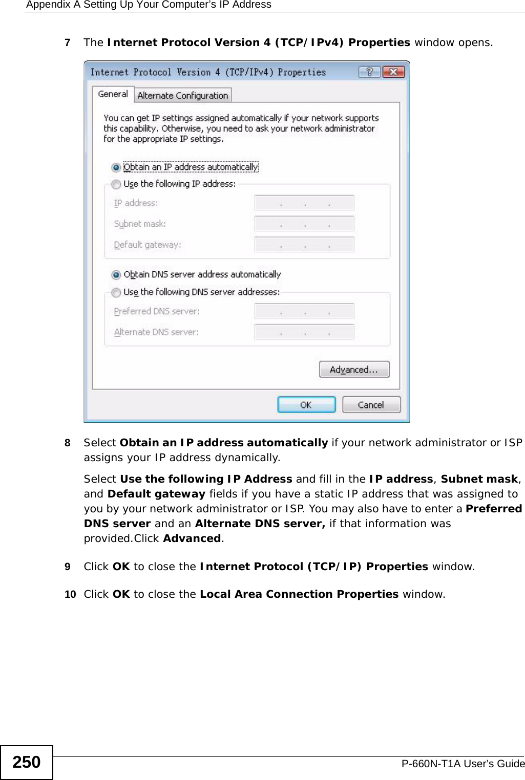
![Appendix A Setting Up Your Computer’s IP AddressP-660N-T1A User’s Guide2465The Internet Protocol TCP/IP Properties window opens.6Select Obtain an IP address automatically if your network administrator or ISP assigns your IP address dynamically.Select Use the following IP Address and fill in the IP address, Subnet mask, and Default gateway fields if you have a static IP address that was assigned to you by your network administrator or ISP. You may also have to enter a Preferred DNS server and an Alternate DNS server, if that information was provided.7Click OK to close the Internet Protocol (TCP/IP) Properties window.8Click OK to close the Local Area Connection Properties window.Verifying Settings1Click Start > All Programs > Accessories > Command Prompt.2In the Command Prompt window, type "ipconfig" and then press [ENTER]. You can also go to Start > Control Panel > Network Connections, right-click a network connection, click Status and then click the Support tab to view your IP address and connection information.](https://usermanual.wiki/ZyXEL-Communications/P660NT1A.user-manual-2/User-Guide-1315612-Page-26.png)
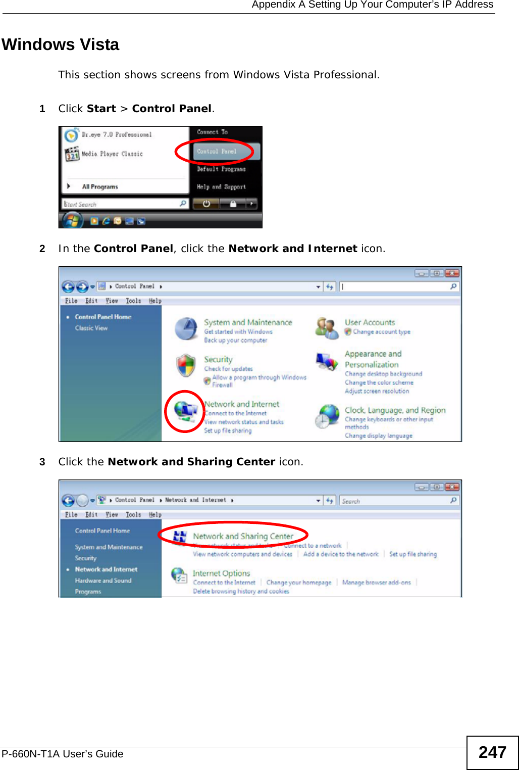
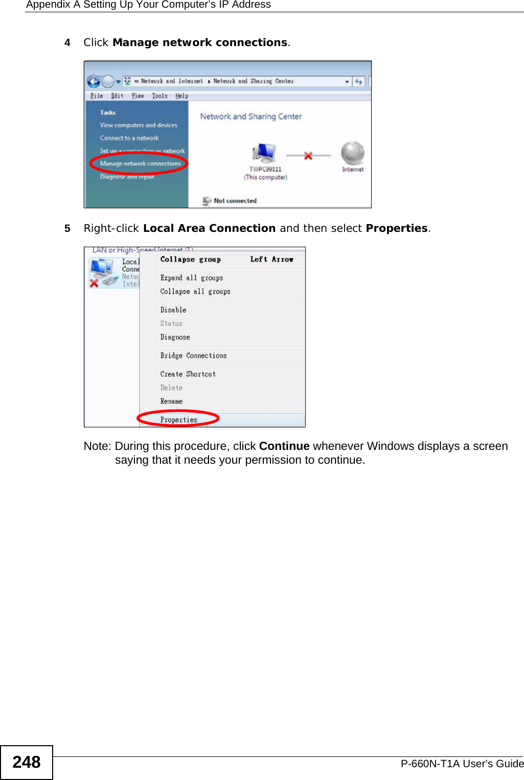
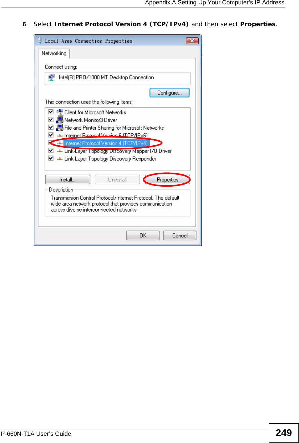
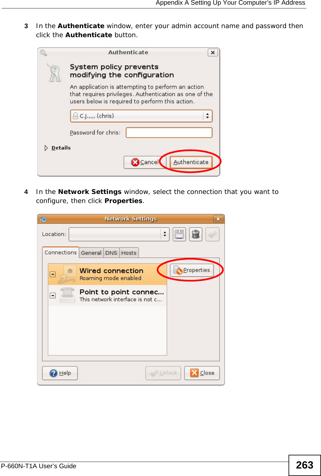
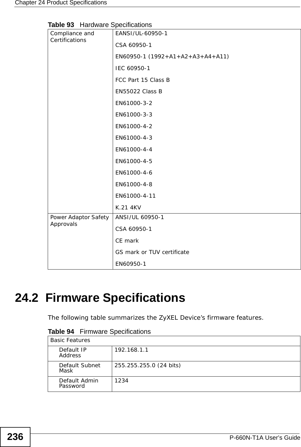
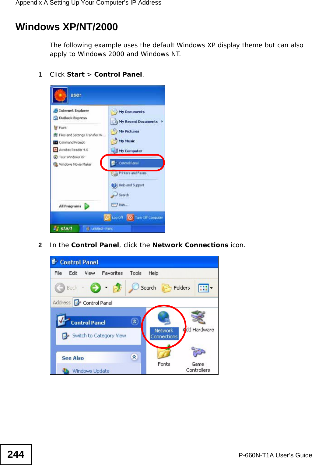
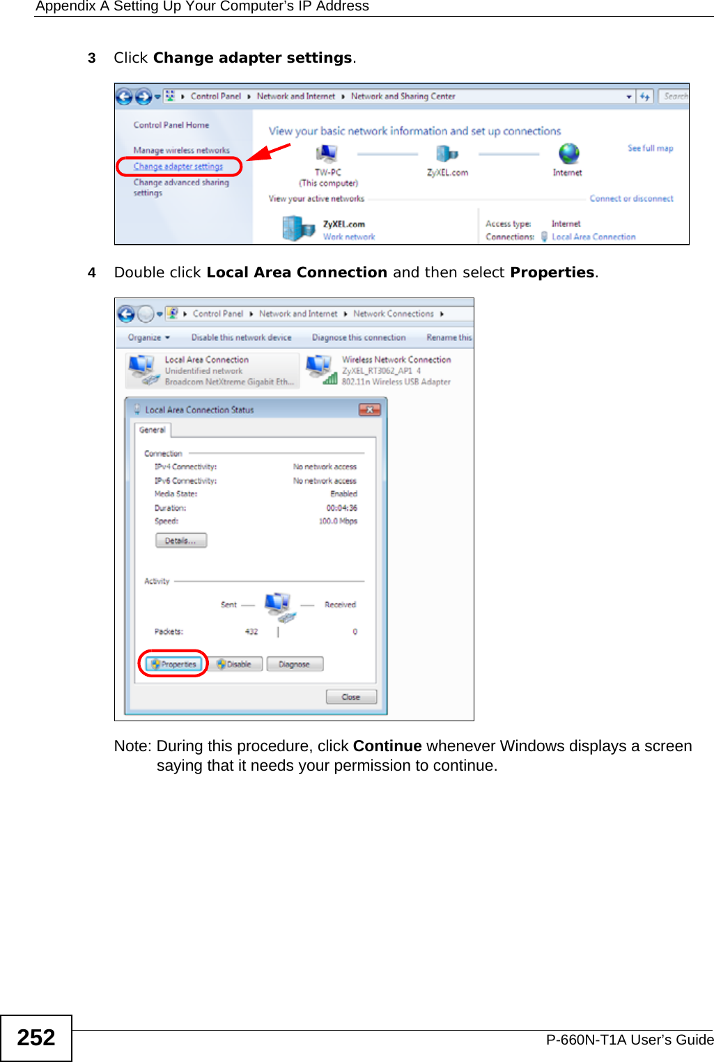
![Appendix A Setting Up Your Computer’s IP AddressP-660N-T1A User’s Guide 251Verifying Settings1Click Start > All Programs > Accessories > Command Prompt.2In the Command Prompt window, type "ipconfig" and then press [ENTER]. You can also go to Start > Control Panel > Network Connections, right-click a network connection, click Status and then click the Support tab to view your IP address and connection information.Windows 7This section shows screens from Windows 7 Enterprise.1Click Start > Control Panel.2In the Control Panel, click View network status and tasks under the Network and Internet category.](https://usermanual.wiki/ZyXEL-Communications/P660NT1A.user-manual-2/User-Guide-1315612-Page-31.png)
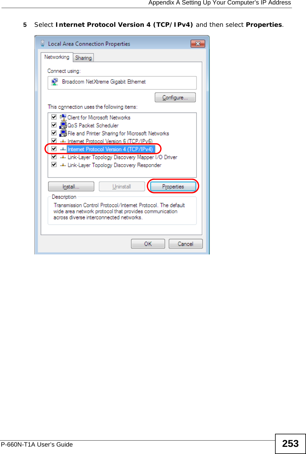
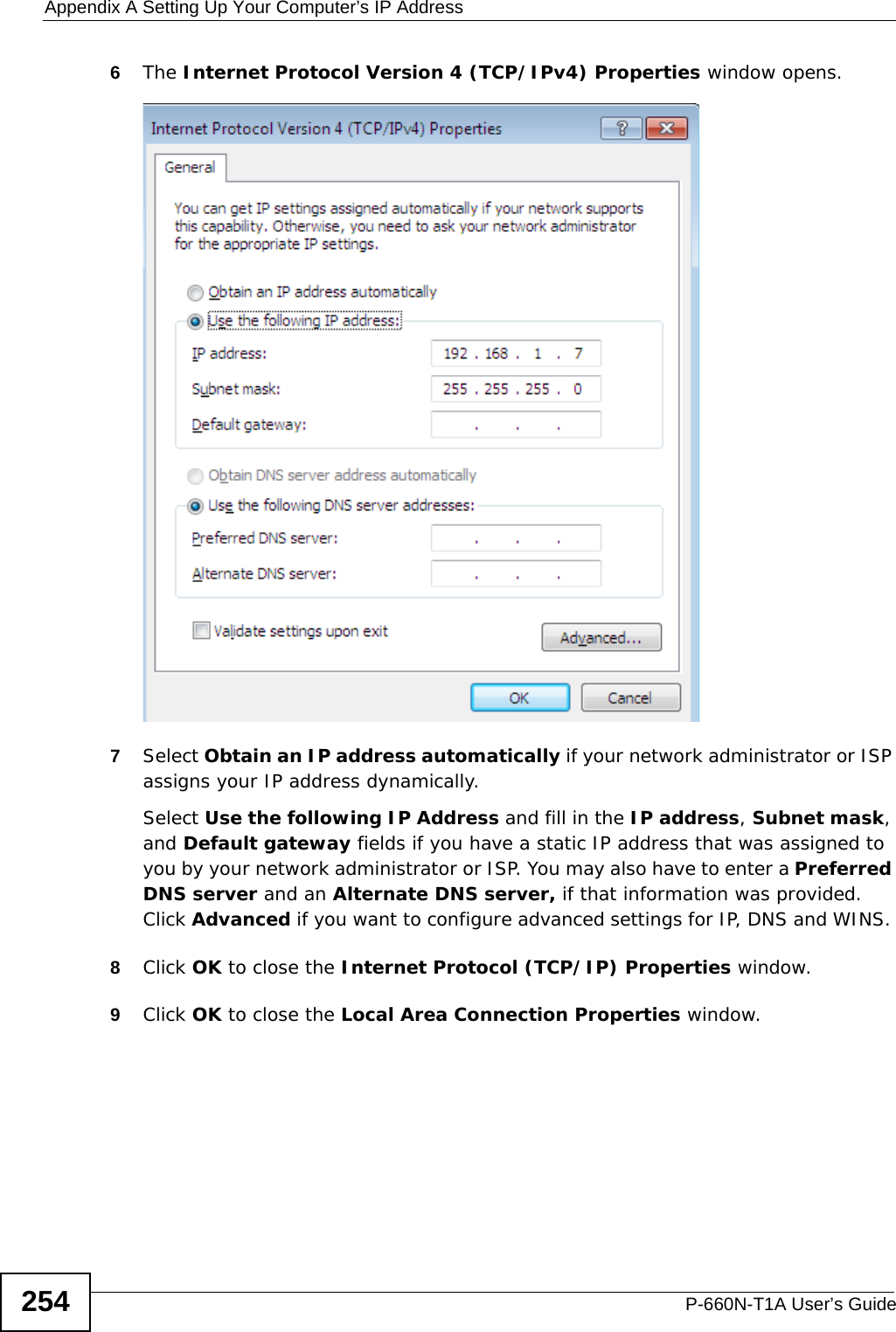
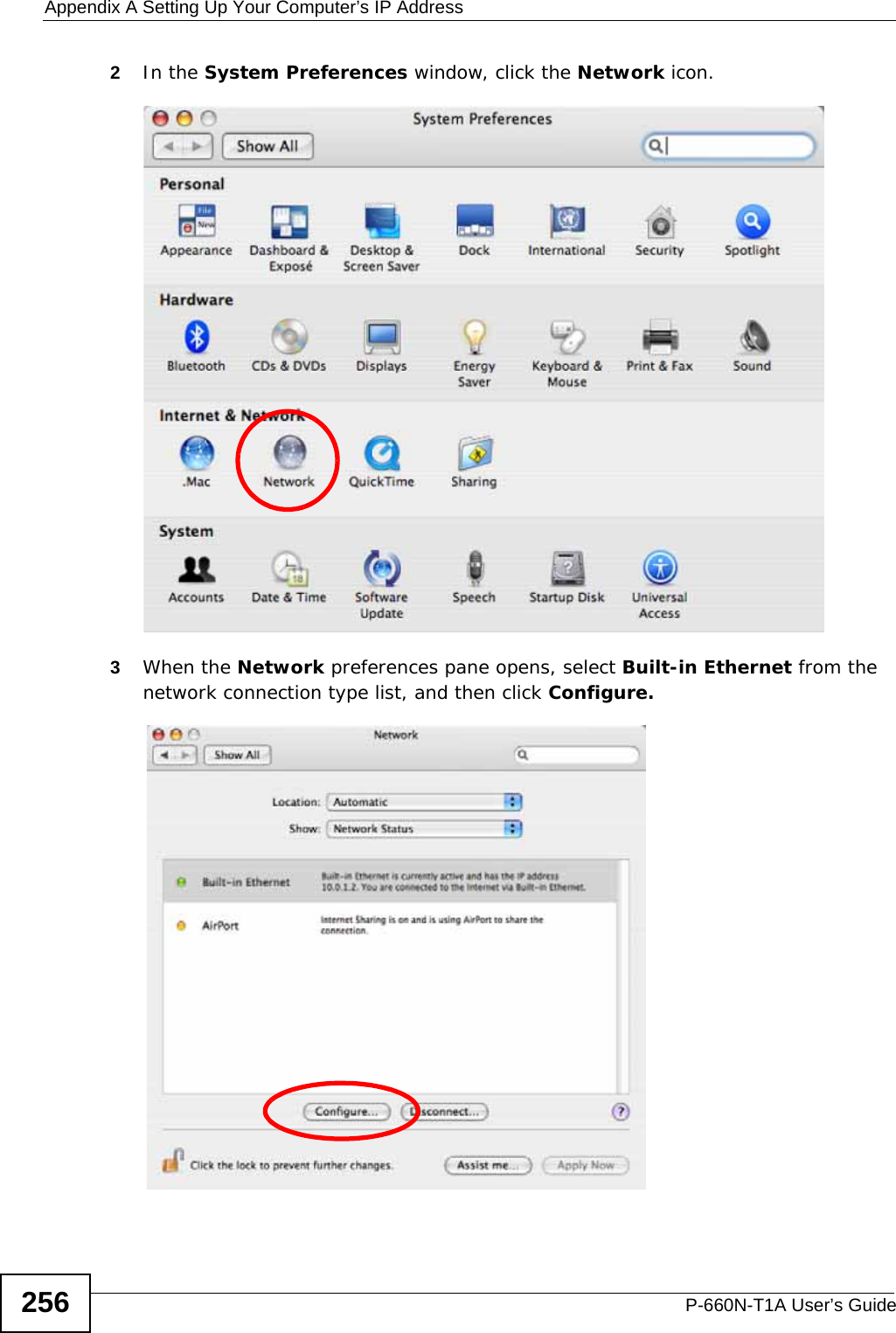
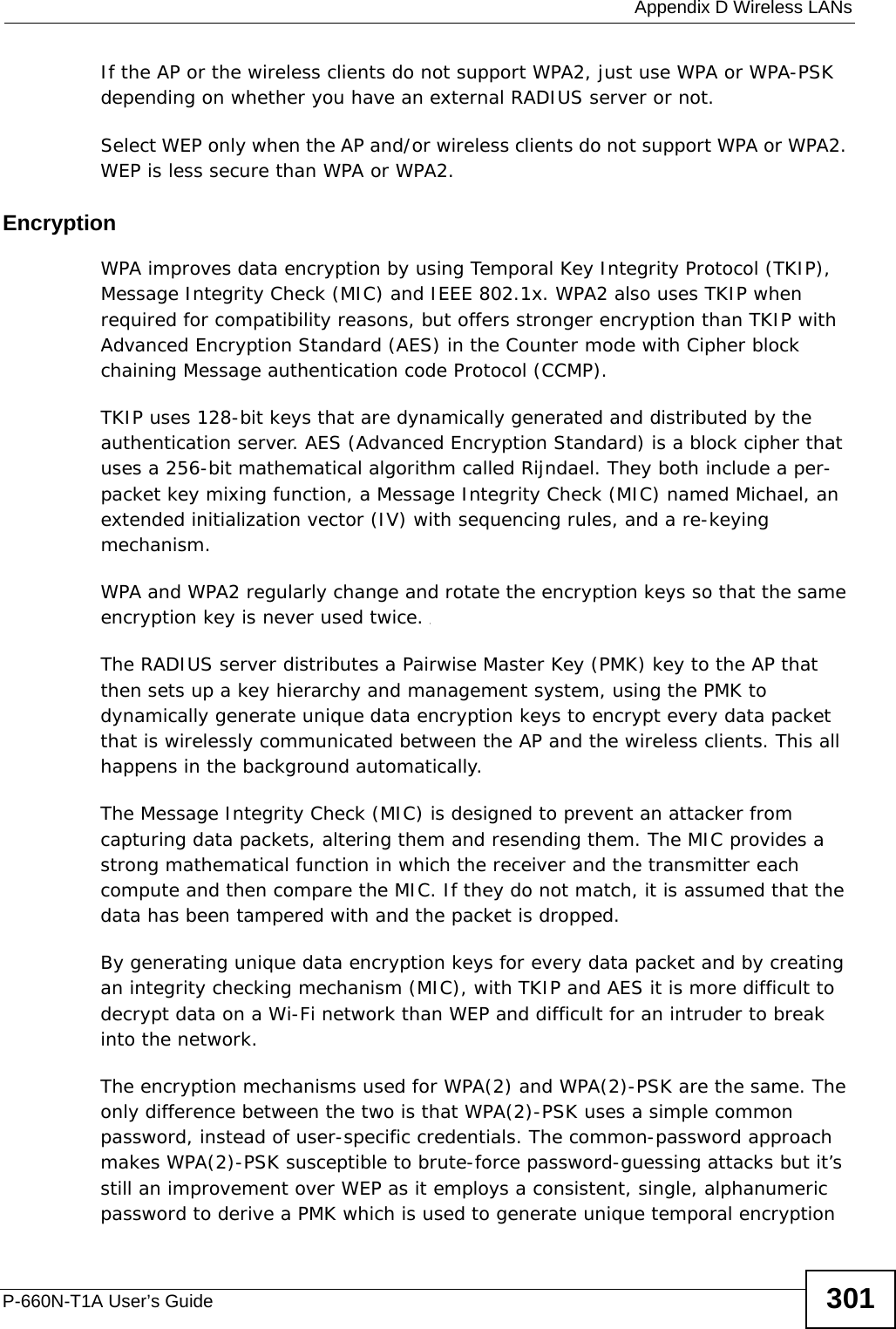
![Appendix A Setting Up Your Computer’s IP AddressP-660N-T1A User’s Guide 255Verifying Settings1Click Start > All Programs > Accessories > Command Prompt.2In the Command Prompt window, type "ipconfig" and then press [ENTER]. 3The IP settings are displayed as follows.Mac OS X: 10.3 and 10.4The screens in this section are from Mac OS X 10.4 but can also apply to 10.3.1Click Apple > System Preferences.](https://usermanual.wiki/ZyXEL-Communications/P660NT1A.user-manual-2/User-Guide-1315612-Page-35.png)