Zinwell ZRF32200 Wireless HD Net Connect Receiver, Wireless HD AV Connect Receiver User Manual NB WHD200 UMen 20160603
Zinwell Corporation Wireless HD Net Connect Receiver, Wireless HD AV Connect Receiver NB WHD200 UMen 20160603
Zinwell >
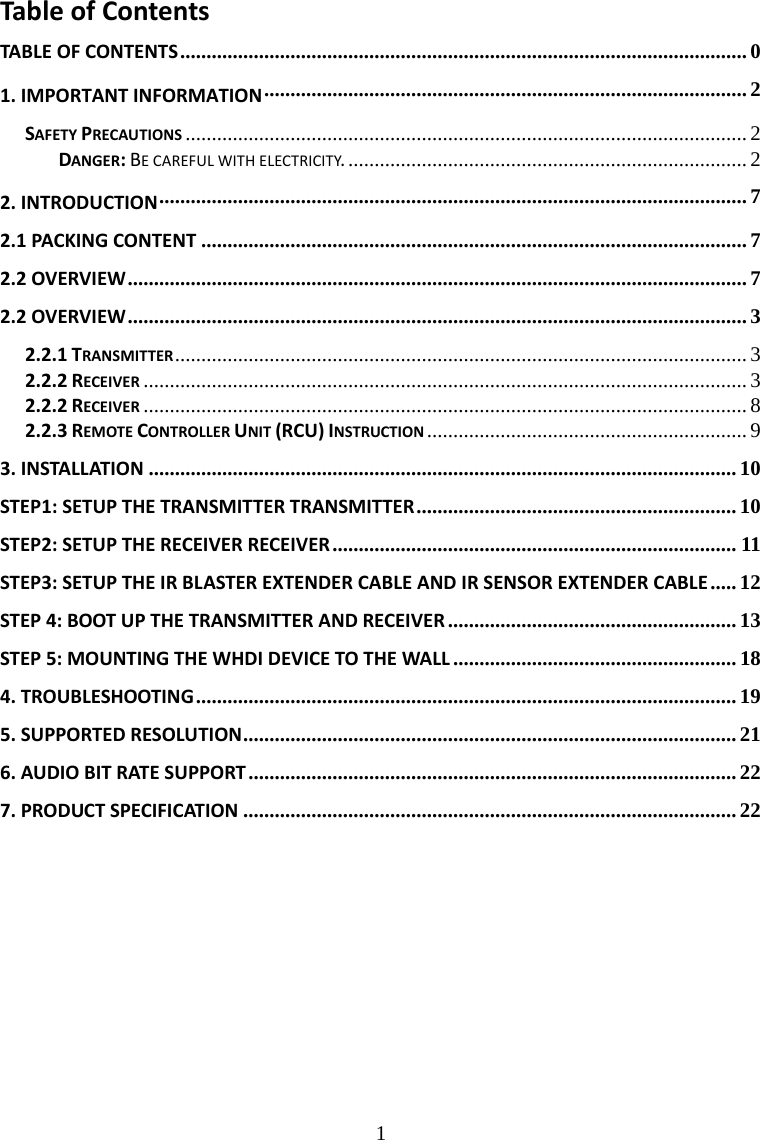
Contents
Users Manual (WHD200R)_rev 2.pdf