Zebra Technologies WMC6300704 PCMCIA Card User Manual MEA Setup and Deployment User s Guide
Zebra Technologies Corporation PCMCIA Card MEA Setup and Deployment User s Guide
UserManual.wiki
>
Zebra Technologies
>
WMC6300704 User Manual
>
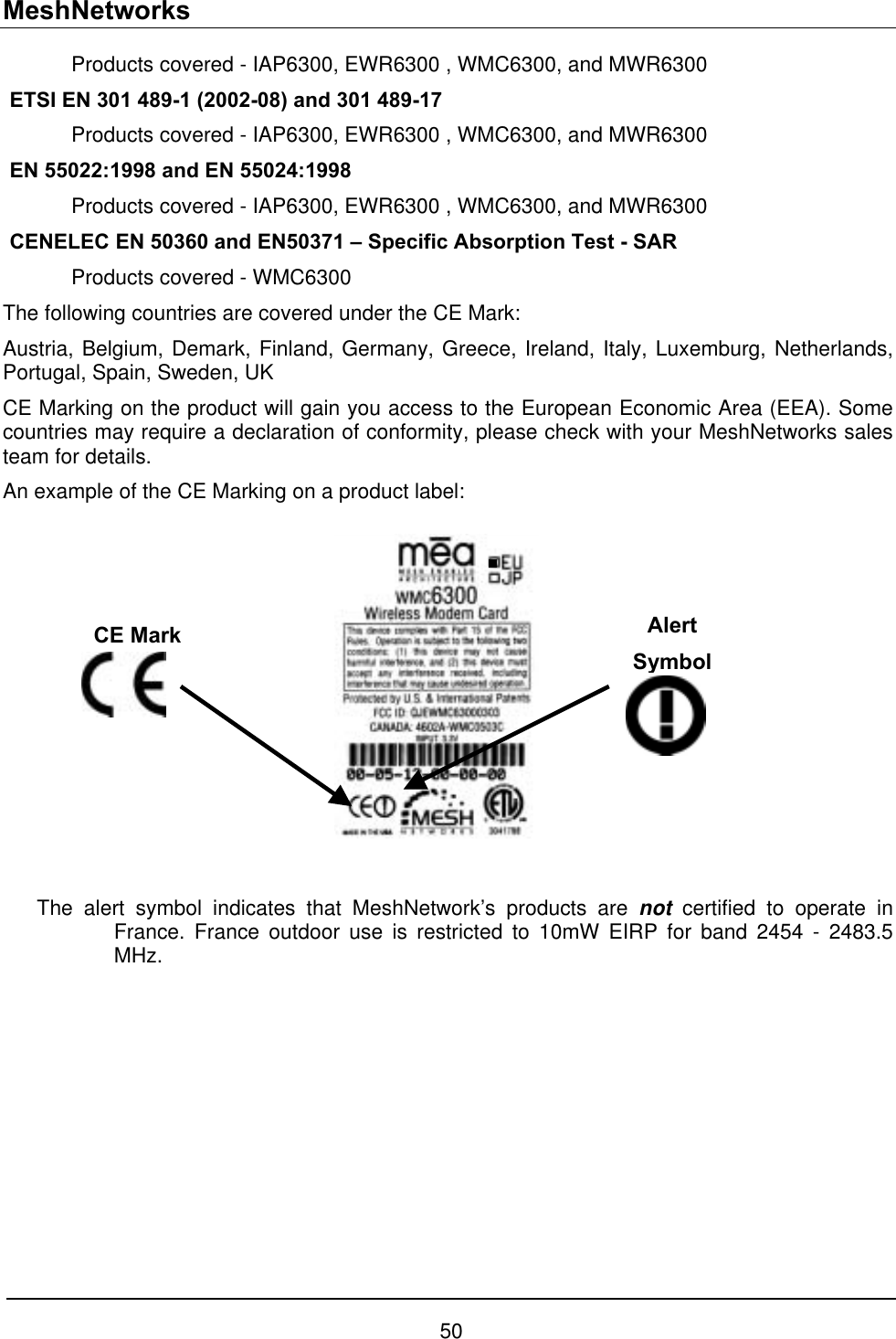
MEA Setup and Installation Guide
Contents
1.
EWR Users Manual
2.
PWR Users Manual
3.
VMM Users Manual
4.
MEA Setup and Installation Guide
5.
MEA WMC6300 Users Guide for Windows Rel 3
6.
MEA WMC6300 Users Guide Pocket PC rev
7.
Pages from QJEWMC6300704 SA
8.
Pages from QJEWMC6300704 User Manual
MEA Setup and Installation Guide
Navigation menu
Upload a User Manual
Namespaces
Wiki Guide
HTML
PDF
Info
Views
User Manual
Discussion / Help
Navigation
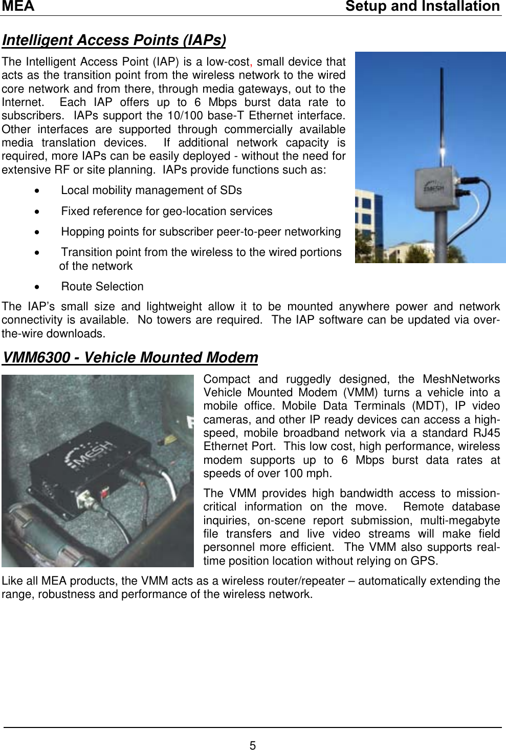
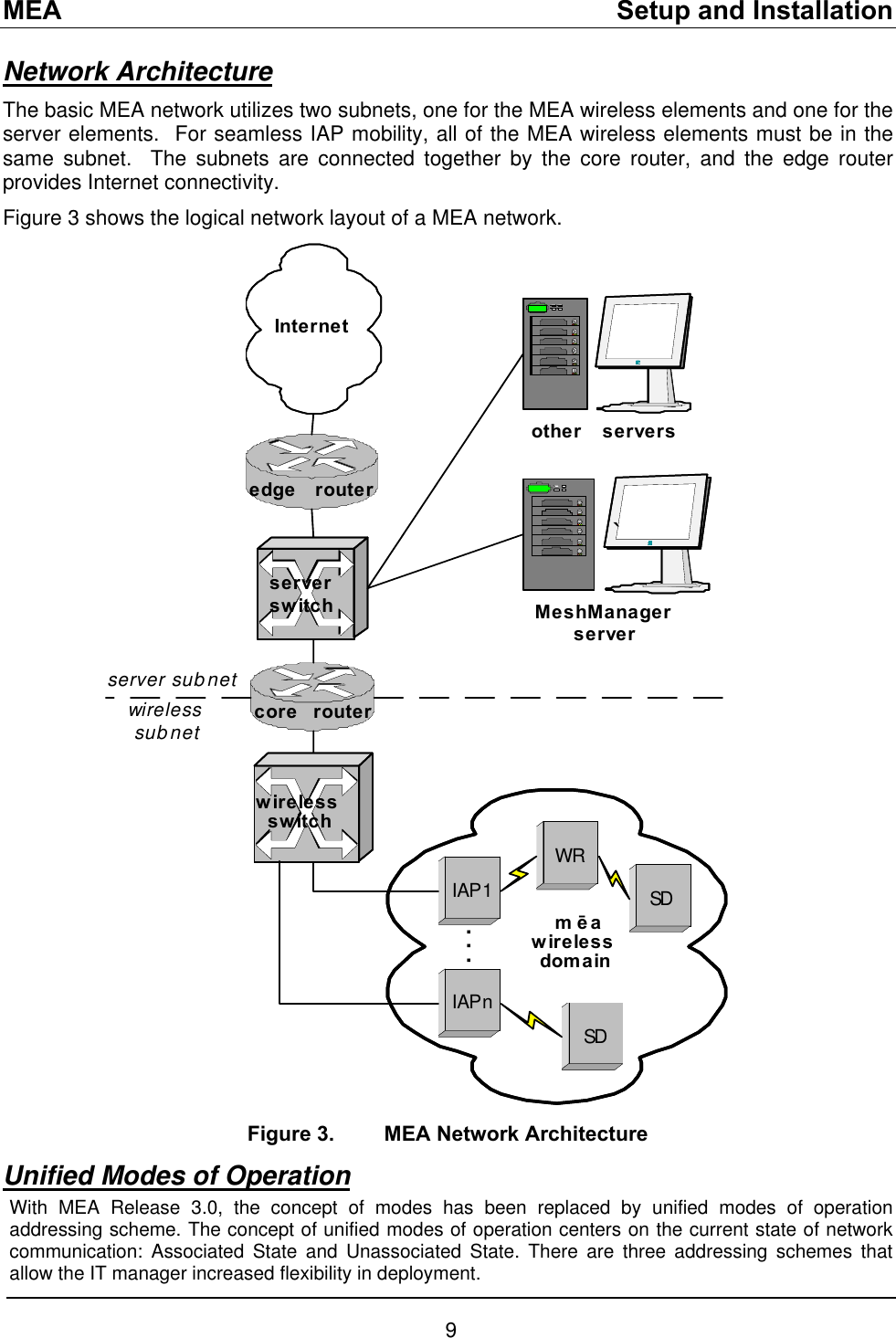
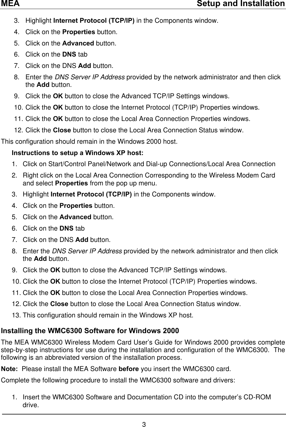
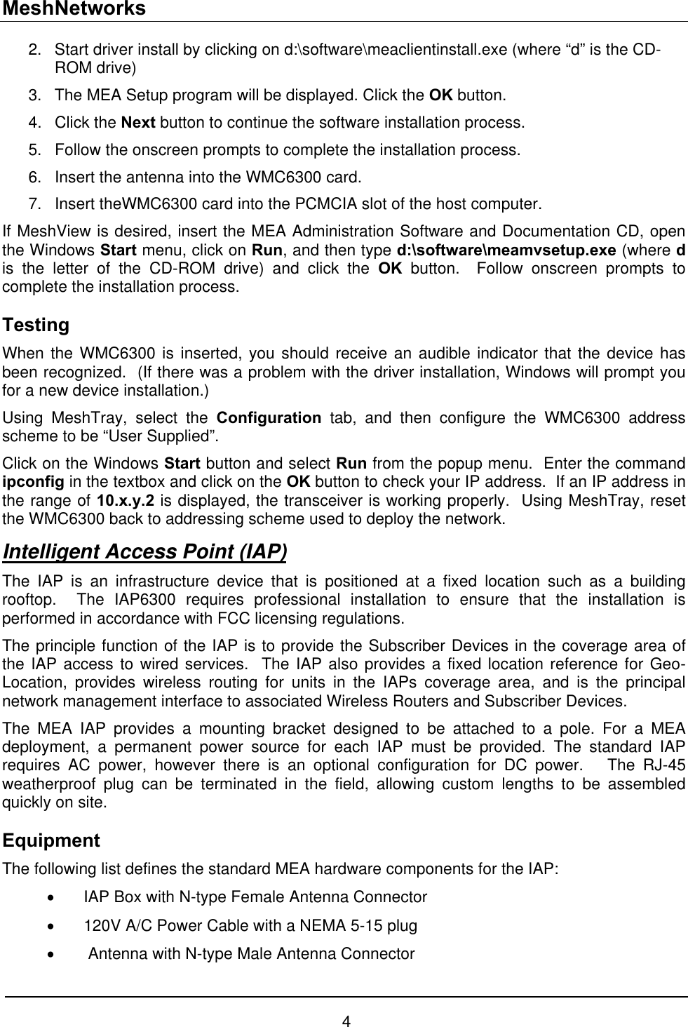
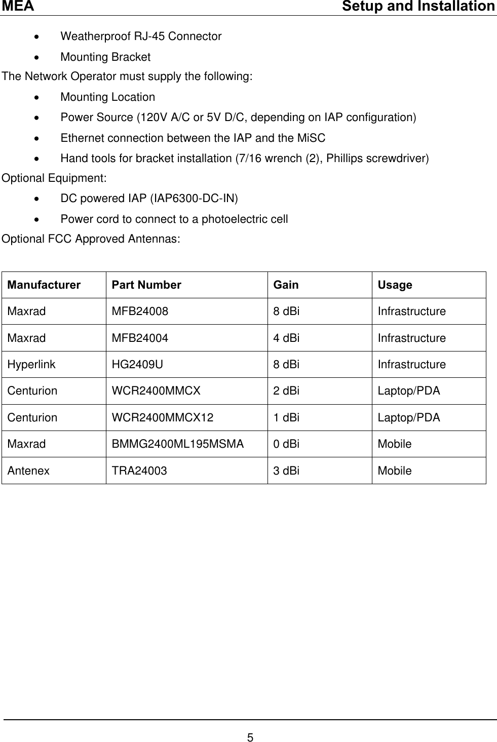
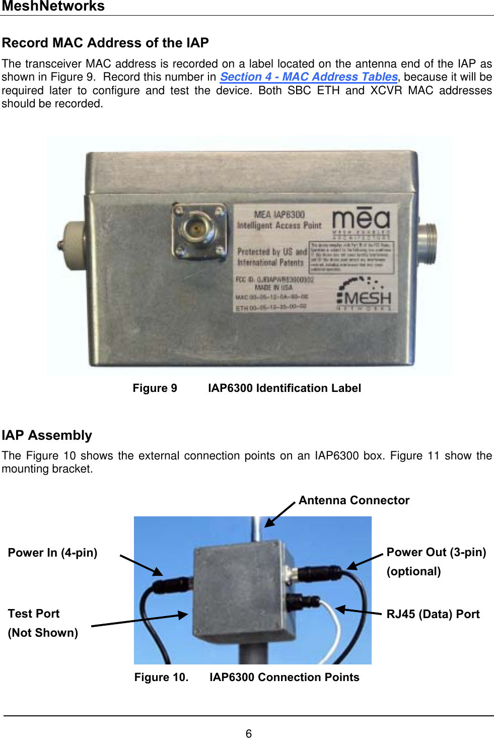
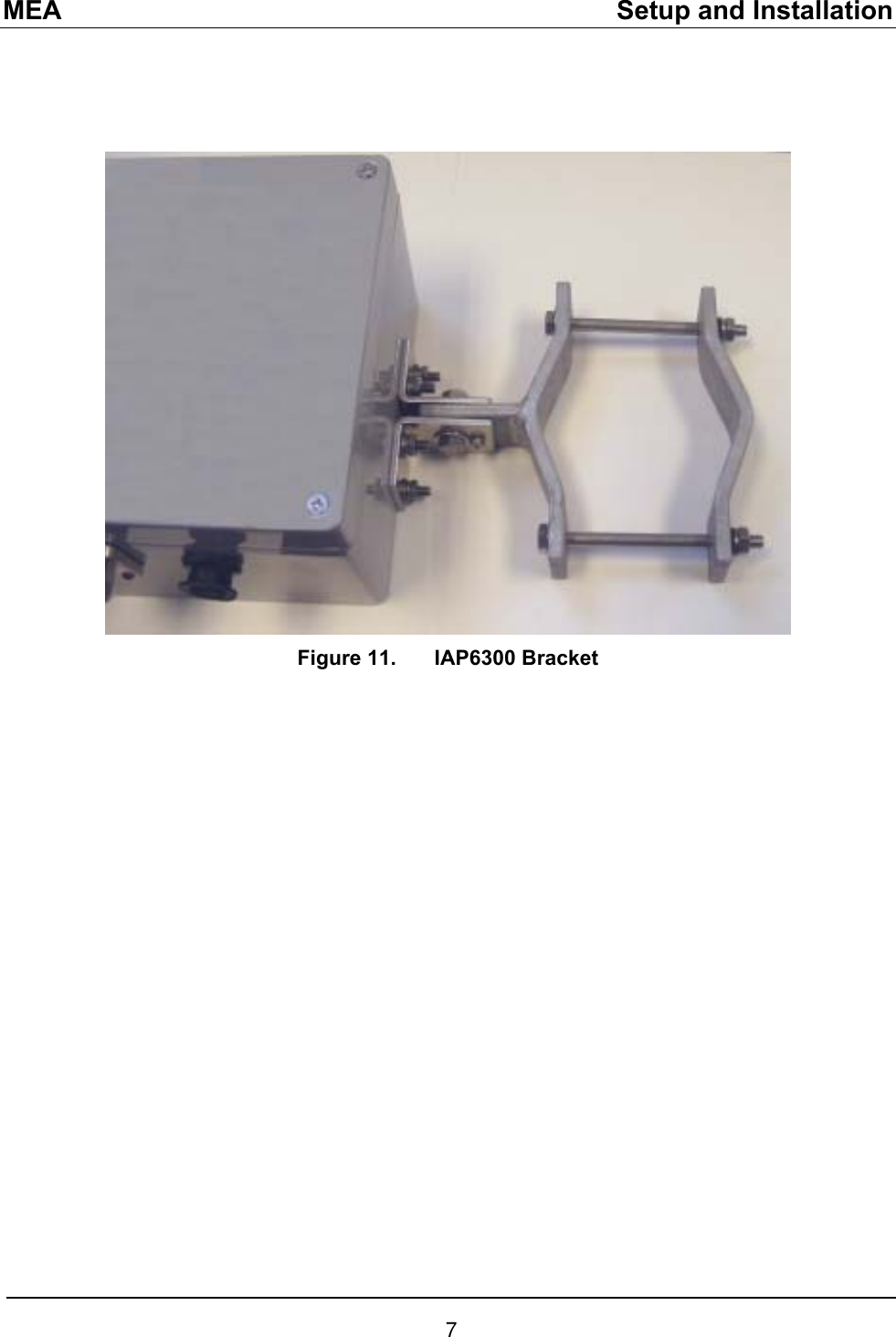
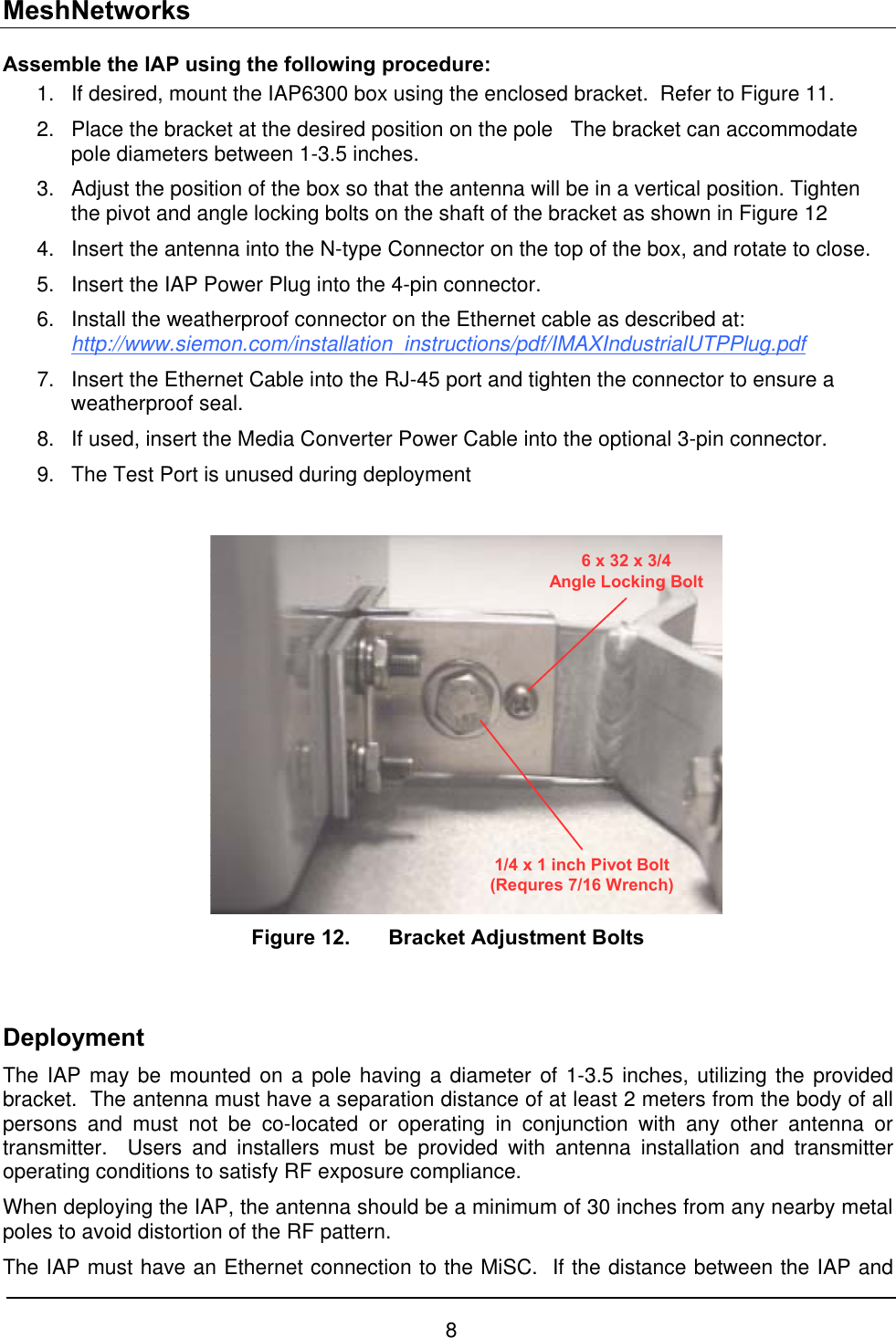
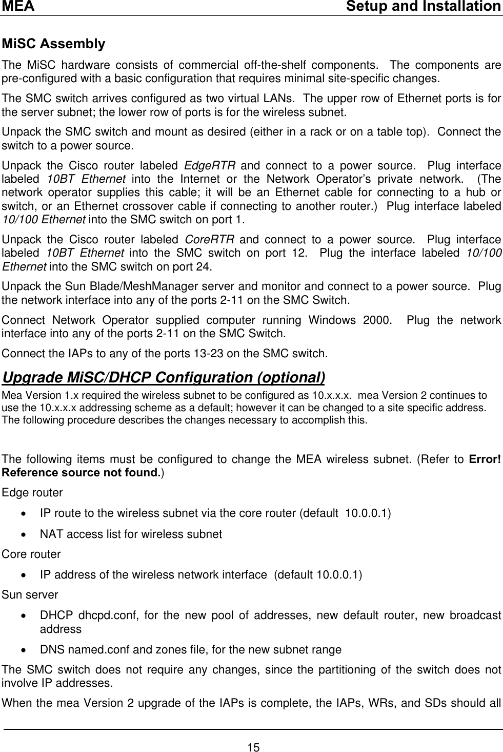
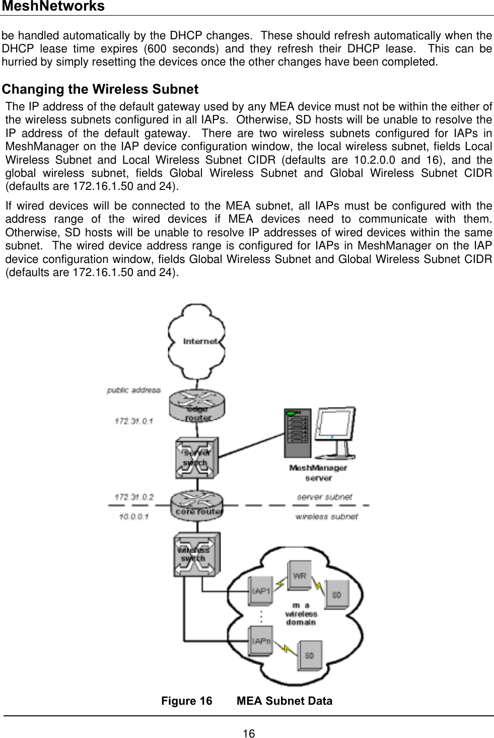
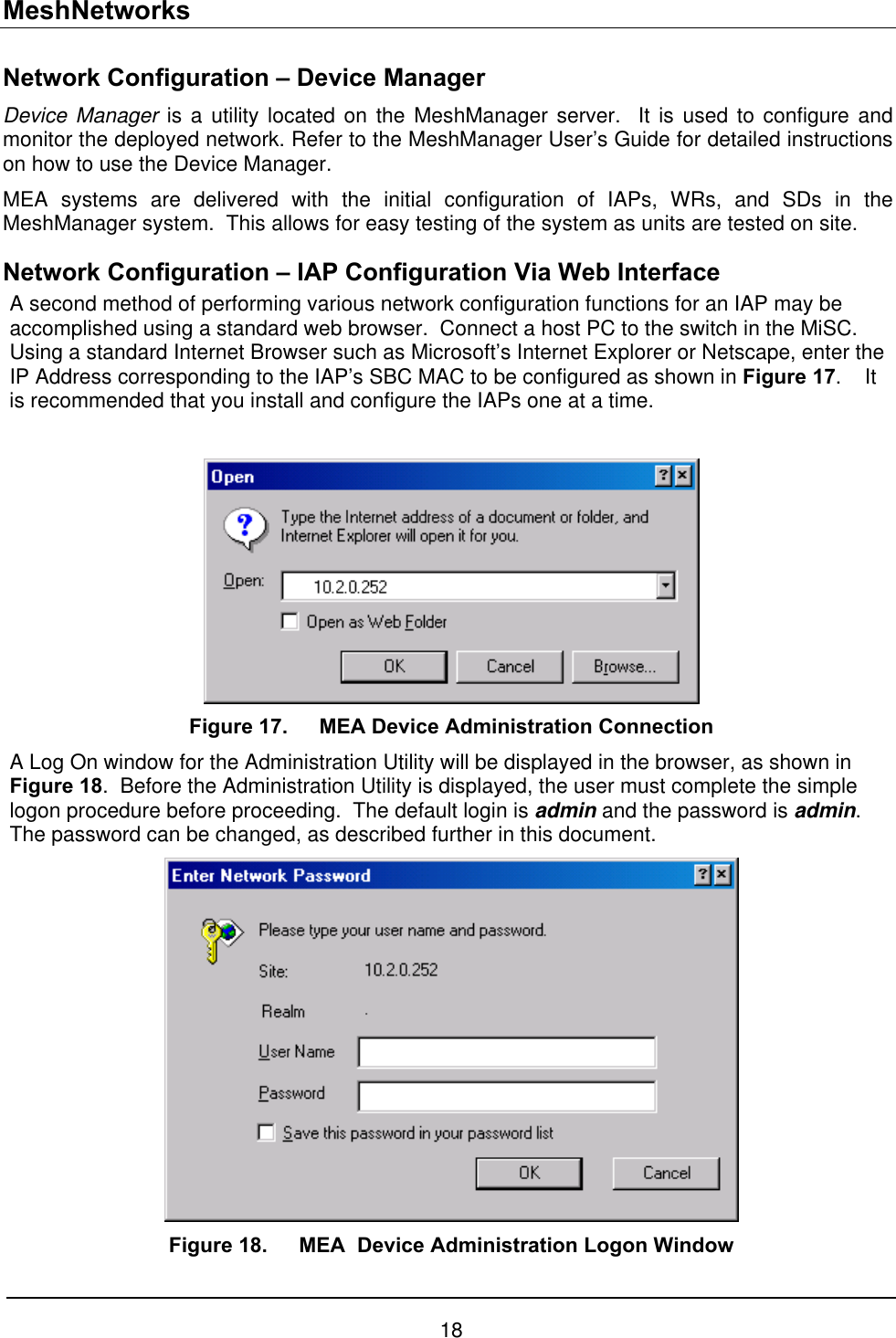
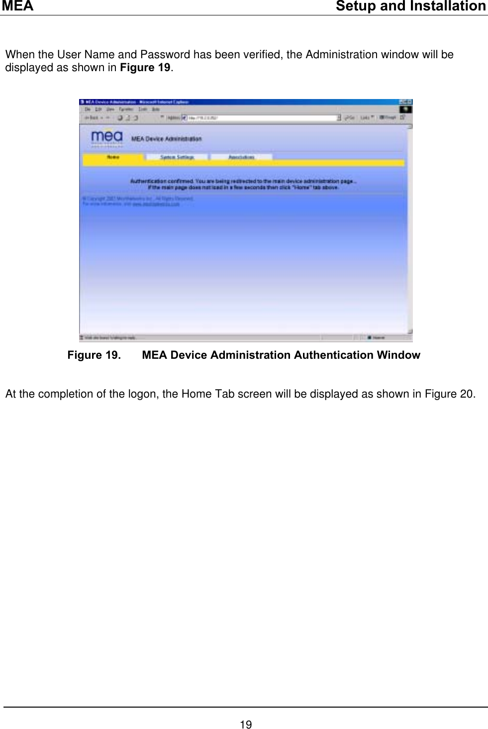
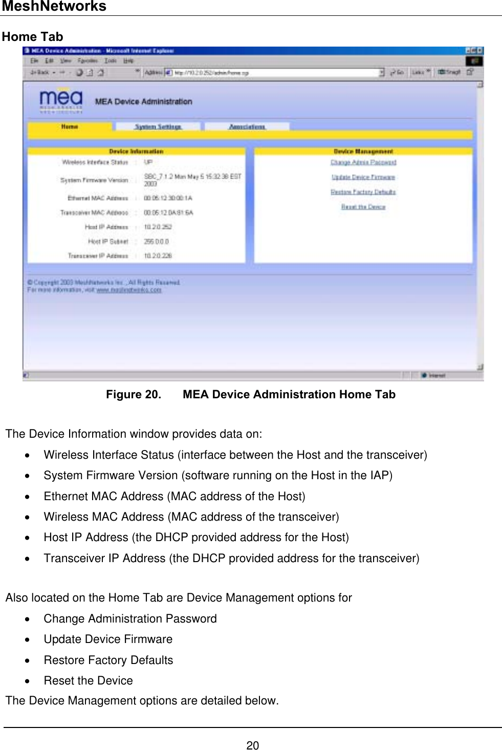
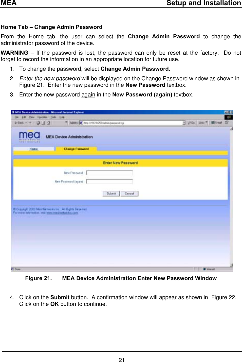
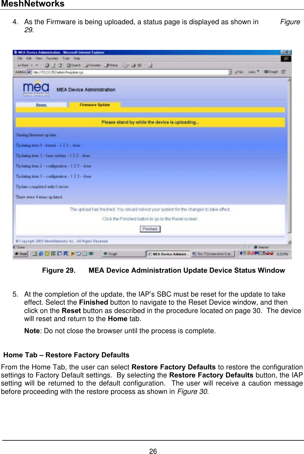
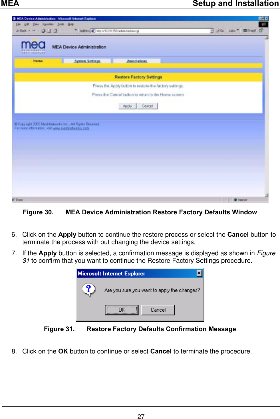
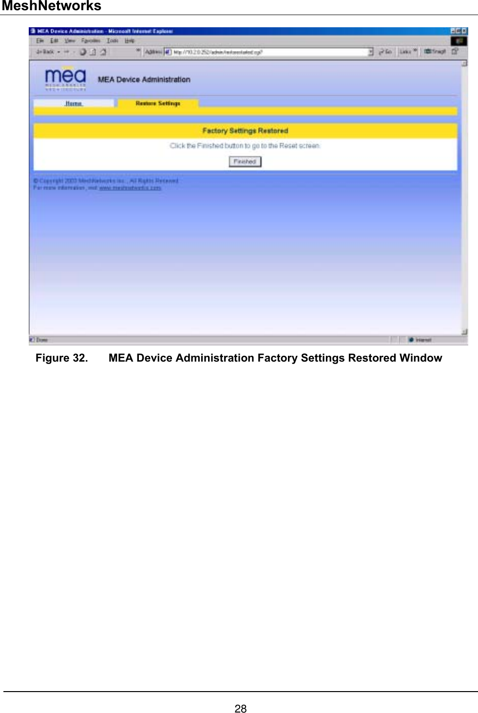
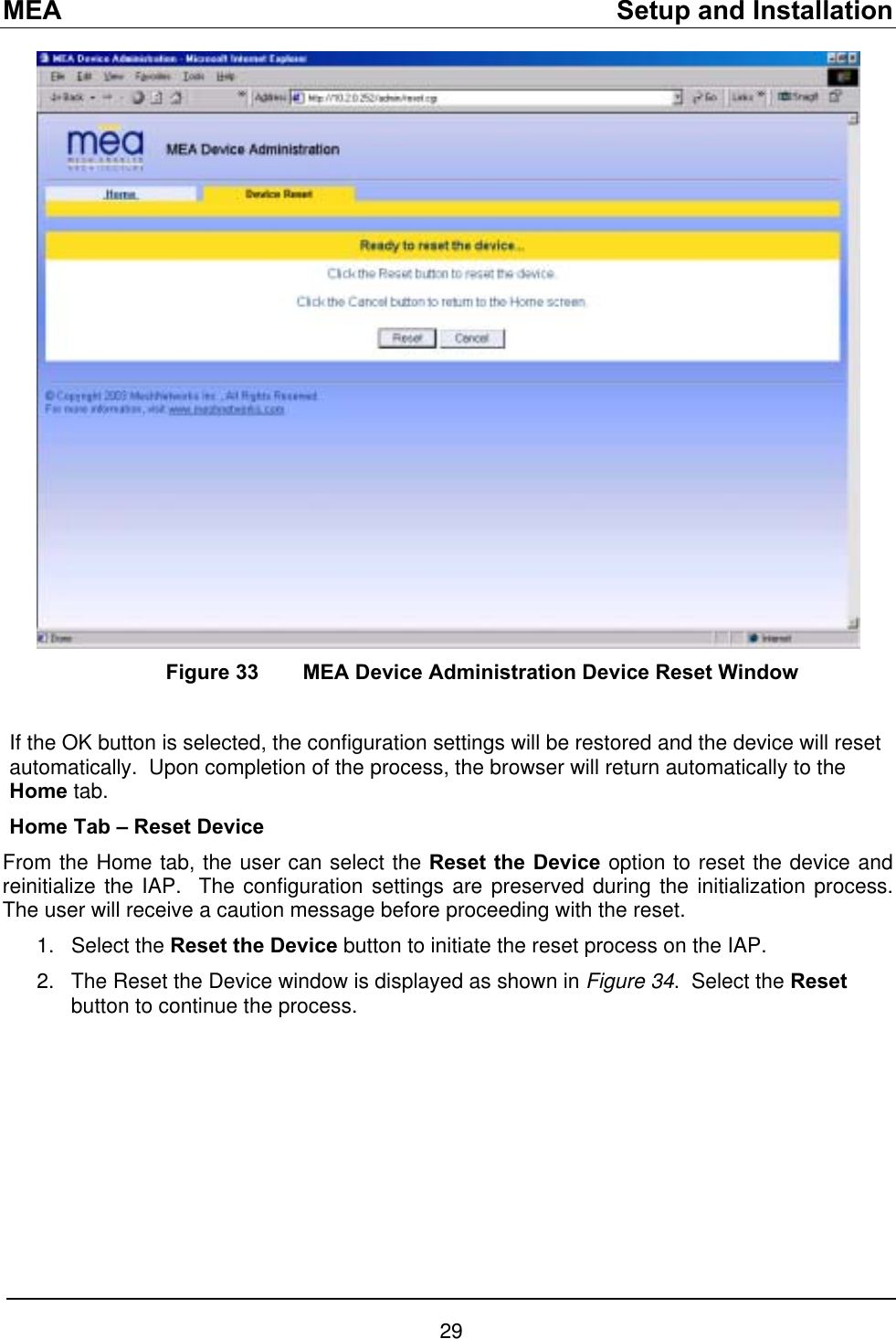
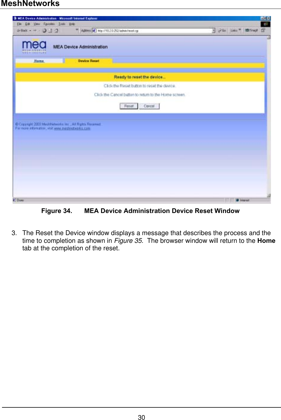
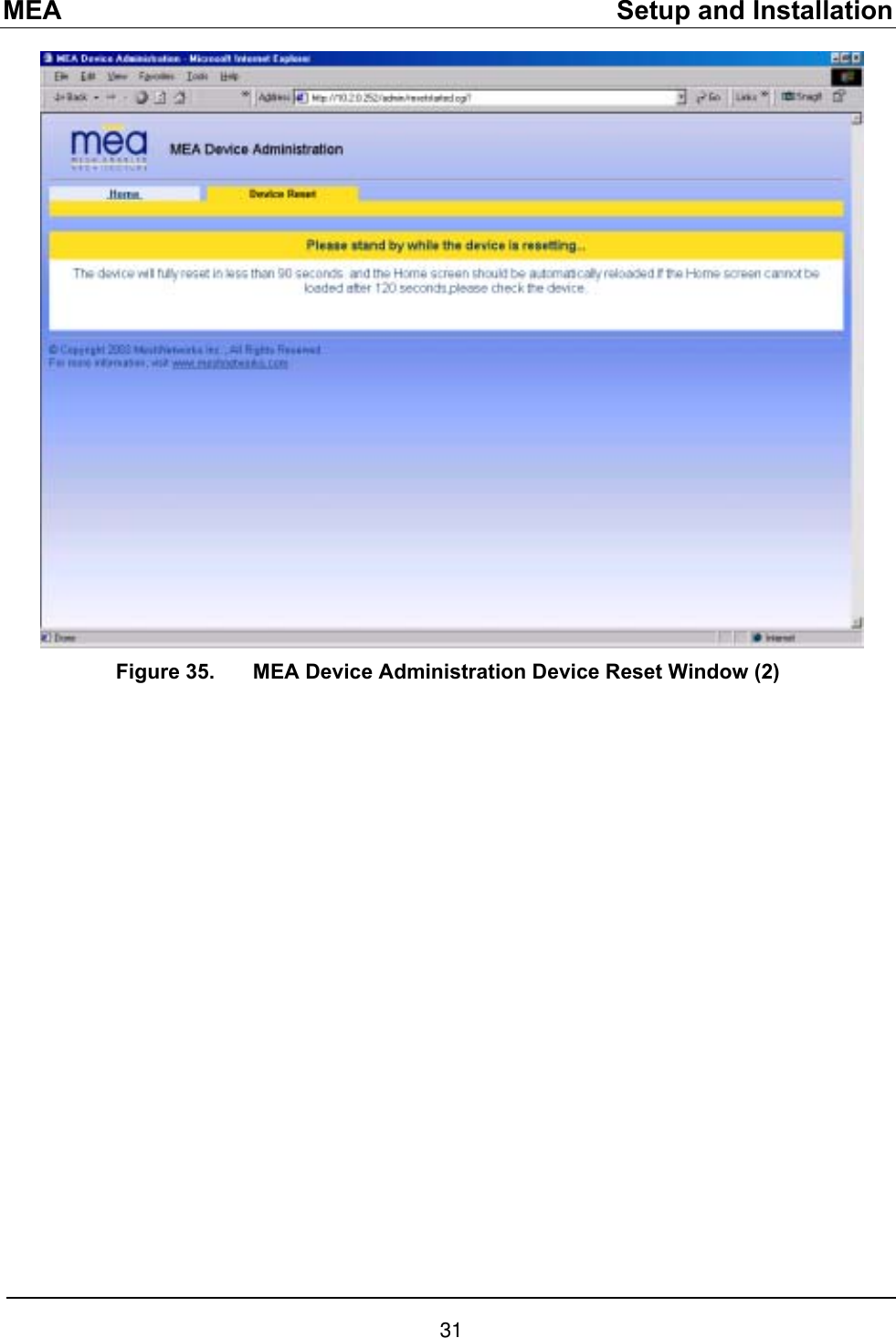
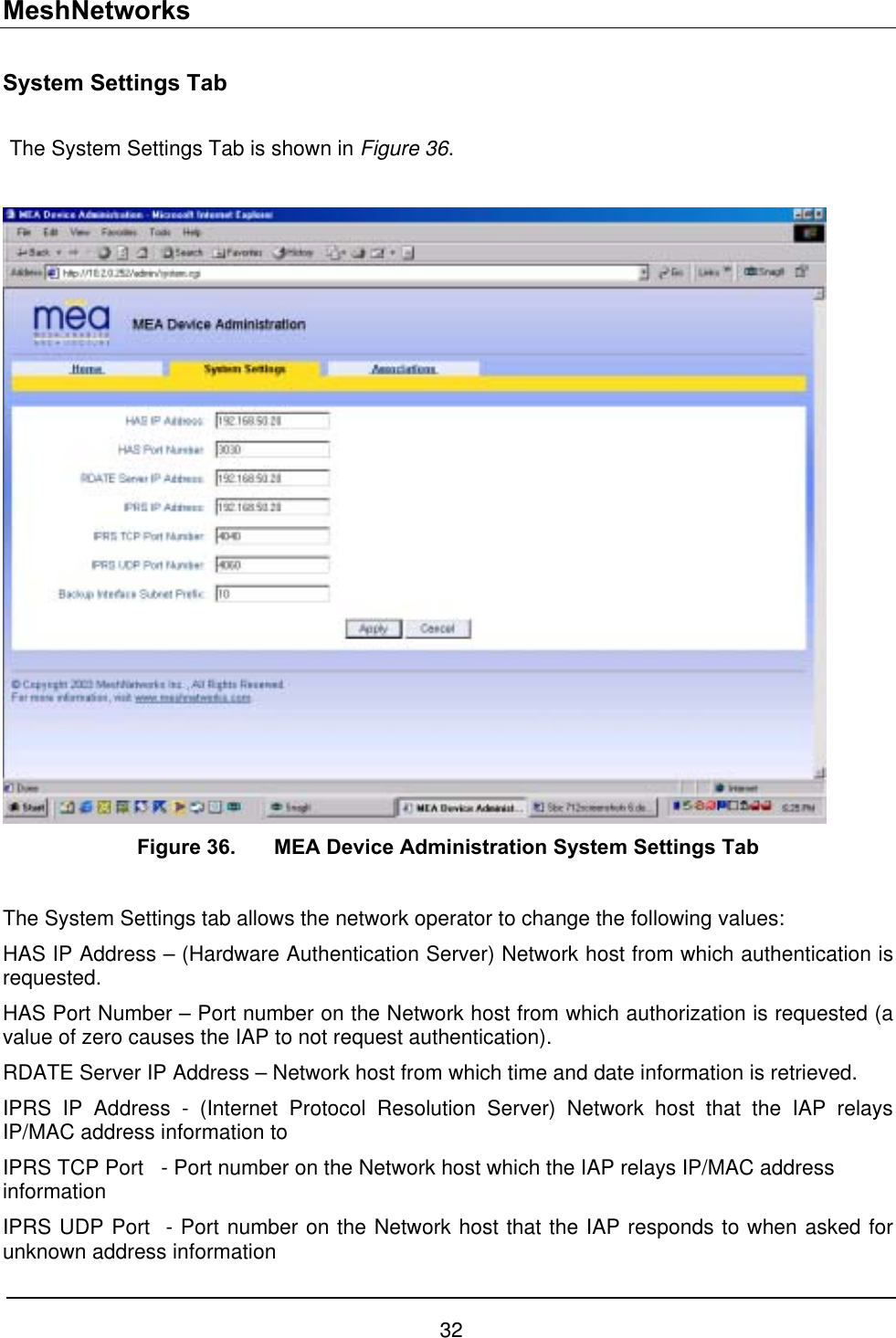
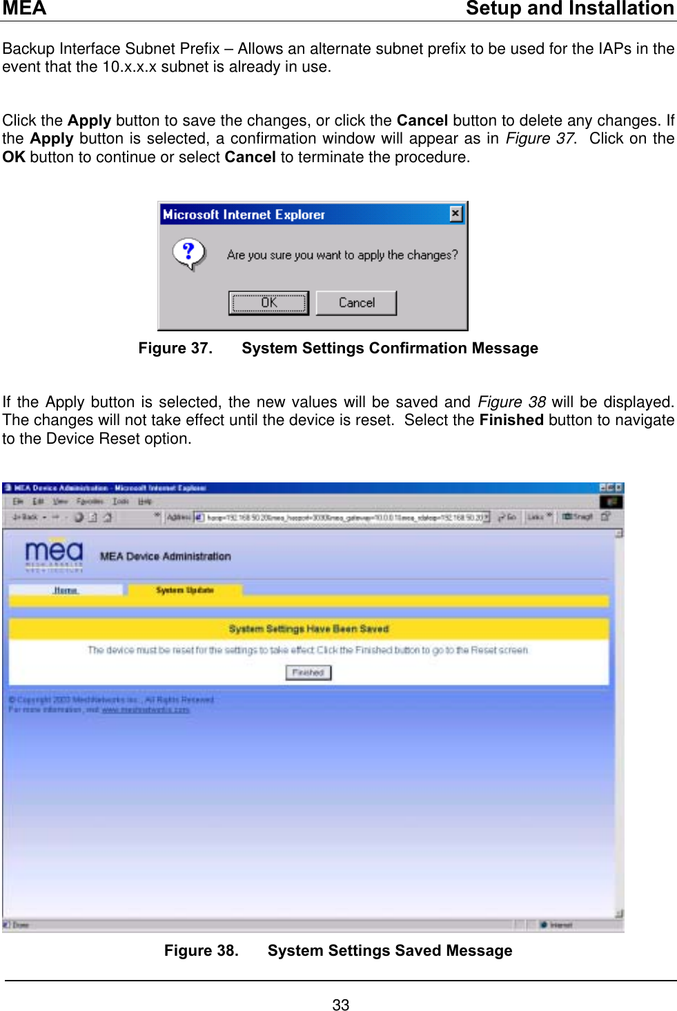
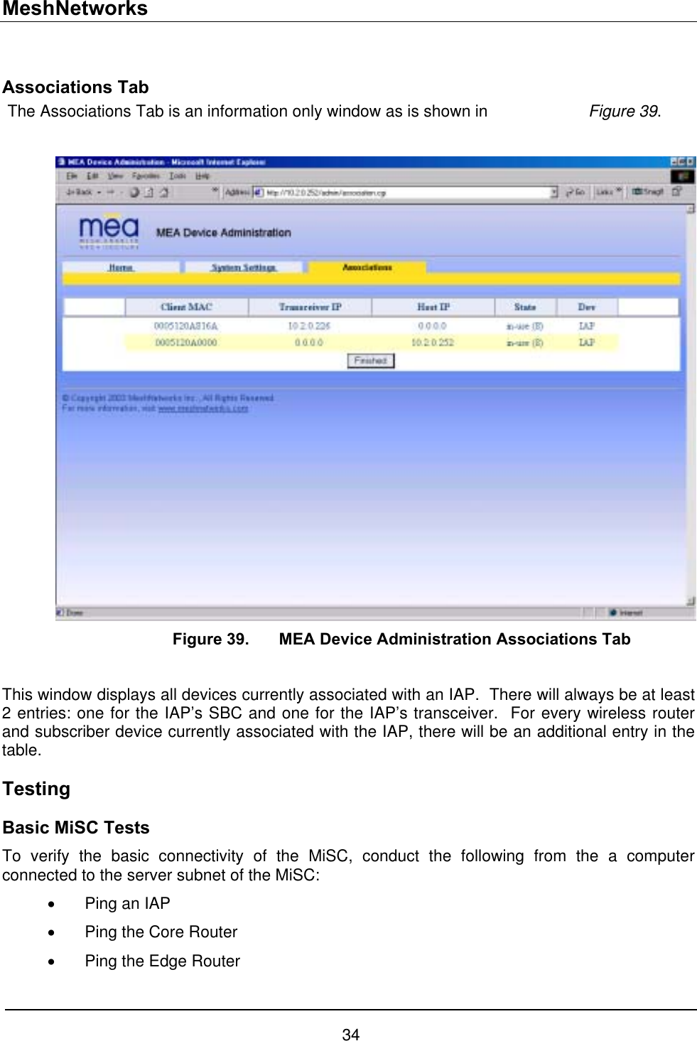
![MEA Setup and Installation Onsite Configuration of Routers EdgeRTR Configuration The EdgeRTR must have on-site configuration done if there is a desire to connect to the Internet. Prior to performing the following steps, obtain the IP address, netmask, and default gateway for the public interface from the Internet Service Provider. These are shown as ip.ip.ip.ip, nm.nm.nm.nm, and gw.gw.gw.gw, respectively, in the instructions below. Also, obtain the IP address of the EdgeRTR, it will be in the form of 172.31.0.1. Telnet into the EdgeRTR from a computer connected to the server subnet. Use the address 172.31.0.1 to connect to the EdgeRTR. Update the public IP information using the commands below Password:g0ld1 EdgeRTR>enable Password:g0ld11 EdgeRTR#configure terminal Enter configuration commands, one per line. End with CNTL/Z. EdgeRTR(config)#interface Ethernet0 EdgeRTR(config-if)#ip address ip.ip.ip.ip mm.nm.nm.nm EdgeRTR(config-if)#exit EdgeRTR(config)#no ip route 0.0.0.0 0.0.0.0 EdgeRTR(config)#ip route 0.0.0.0 0.0.0.0 gw.gw.gw.gw EdgeRTR(config)#exit EdgeRTR#copy running-config startup-config Destination filename [startup-config]? <return> Building configuration... !!!!!!!!!!!!!!!!!!!!!!!!!!!!!!!!!!!!!!!!!!!!!!!!!!!!!!!!!!!!!!!!!!!!!!!!!!!![OK] EdgeRTR#exit EdgeRTR TEST Use a computer connected to the switch (in either the server or wireless subnet) to ping to the ISP gateway IP. Next, test access to the Internet using a web browser. If this fails troubleshoot and retry. 17](https://usermanual.wiki/Zebra-Technologies/WMC6300704.MEA-Setup-and-Installation-Guide/User-Guide-492133-Page-41.png)