Zebra Technologies TFF-2000-00AA TFF-2220, WhereCall IV User Manual Users Guide
Zebra Technologies Corporation TFF-2220, WhereCall IV Users Guide
UserManual.wiki
>
Zebra Technologies
>
TFF-2000-00AA User Manual
>
Users Guide
Contents
1.
Users Manual
2.
Users Guide
Users Guide
Navigation menu
Upload a User Manual
Namespaces
Wiki Guide
HTML
PDF
Info
Views
User Manual
Discussion / Help
Navigation
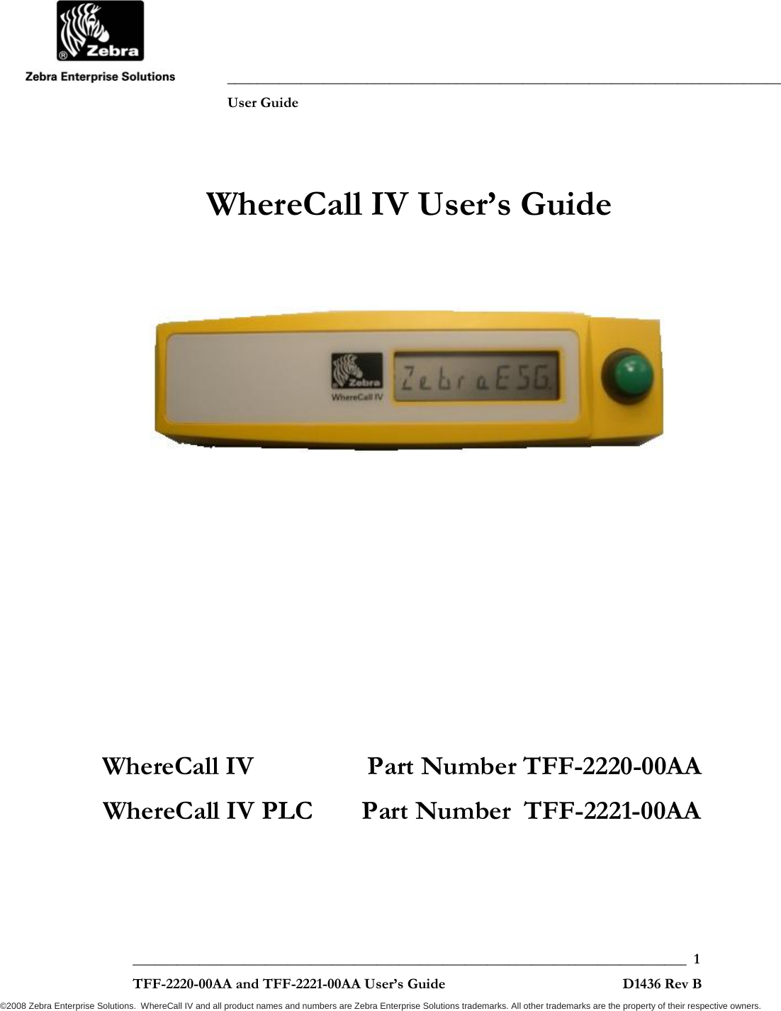
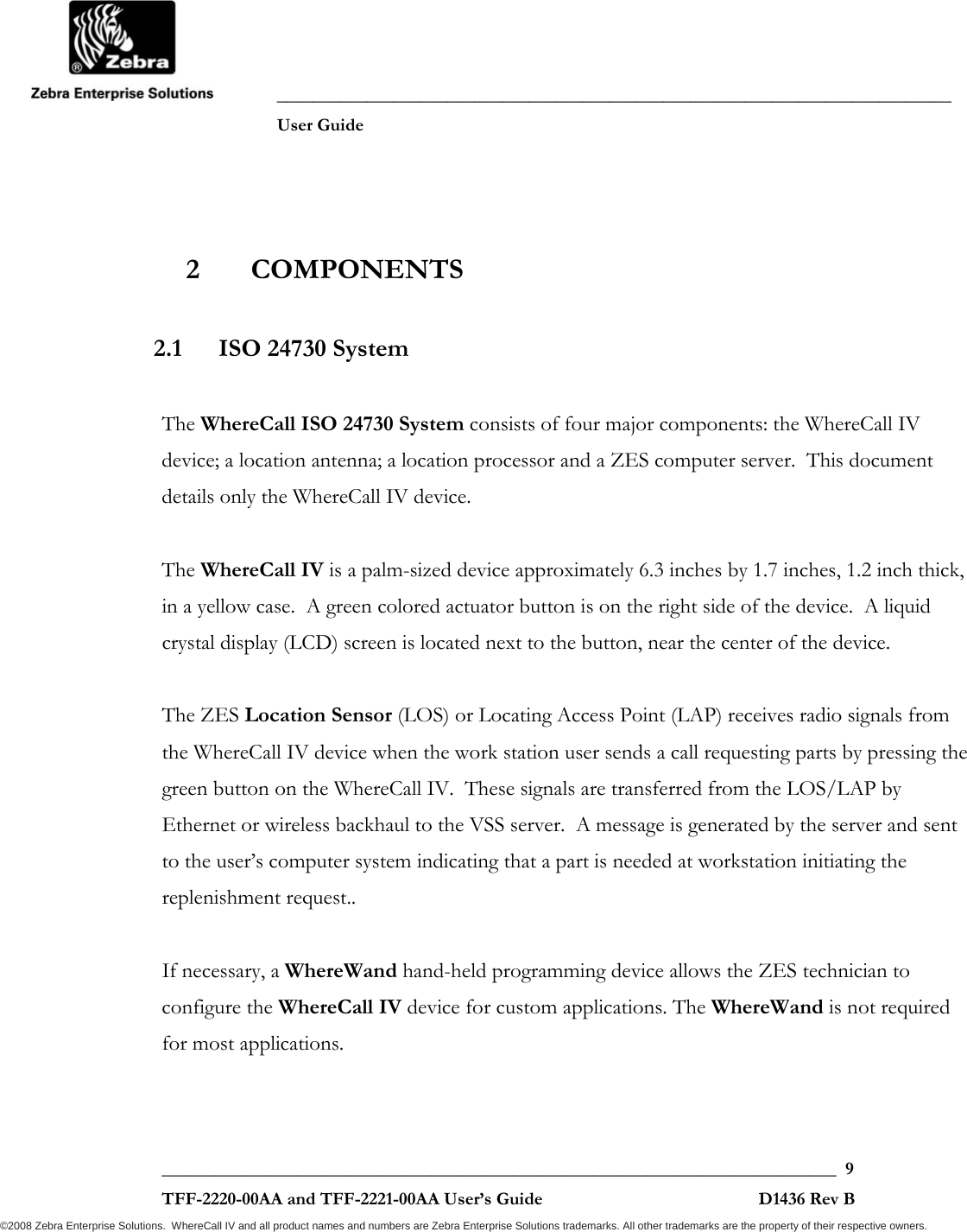
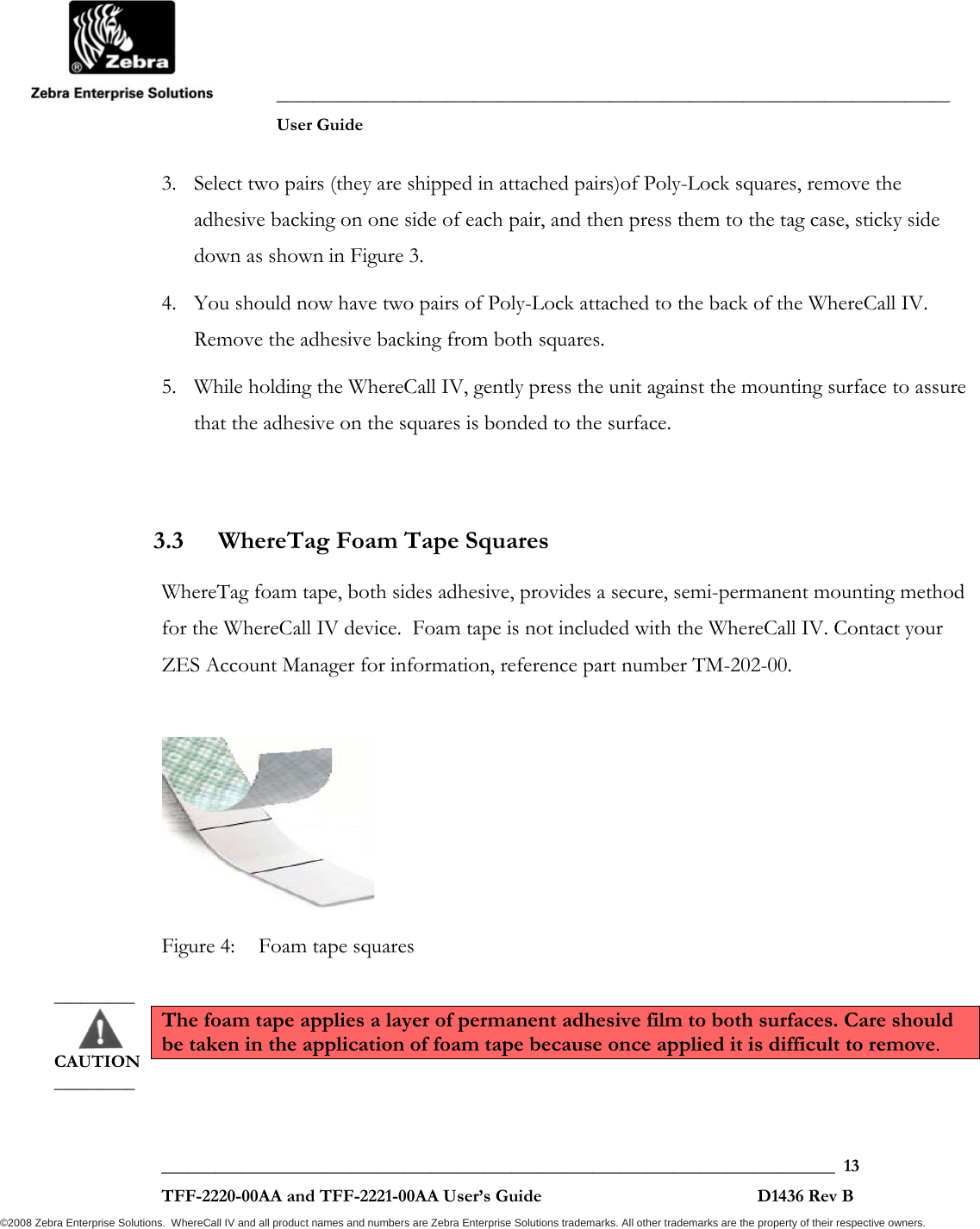
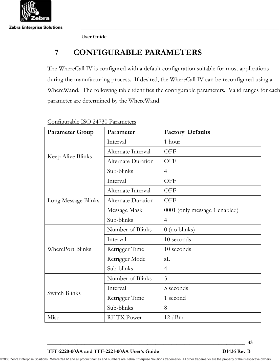
![___________________________________________________________________________ User Guide ___________________________________________________________________________ 16 TFF-2220-00AA and TFF-2221-00AA User’s Guide D1436 Rev B ©2008 Zebra Enterprise Solutions. WhereCall IV and all product names and numbers are Zebra Enterprise Solutions trademarks. All other trademarks are the property of their respective owners. Figure 7: Attaching WhereCall IV to Mounting Bracket 3.6 Installing WhereCall IV with Cable Hanging Bracket 1. Using a 5/64 inch hex drive bit, remove 4 screws from the bottom cover as shown in Figure 7. 2. Align the mounting bracket so the 4 screw holes align with the 4 screw holes in the WhereCall IV bottom cover. Be sure the four counter sunk holes in the mounting bracket are visible and not against the WhereCall IV bottom cover. Reinsert the screws through the bracket and into the bottom cover of WhereCall IV, with torque set to 6.0 + .6 inch-pounds [0.68 + 0.07 Newton-meters]. See figure 8. 3. Hang the mounting bracket in the desired location by threading the cable into the slot on the end of the bracket. Remove and save these 4 screws](https://usermanual.wiki/Zebra-Technologies/TFF-2000-00AA.Users-Guide/User-Guide-1140560-Page-16.png)
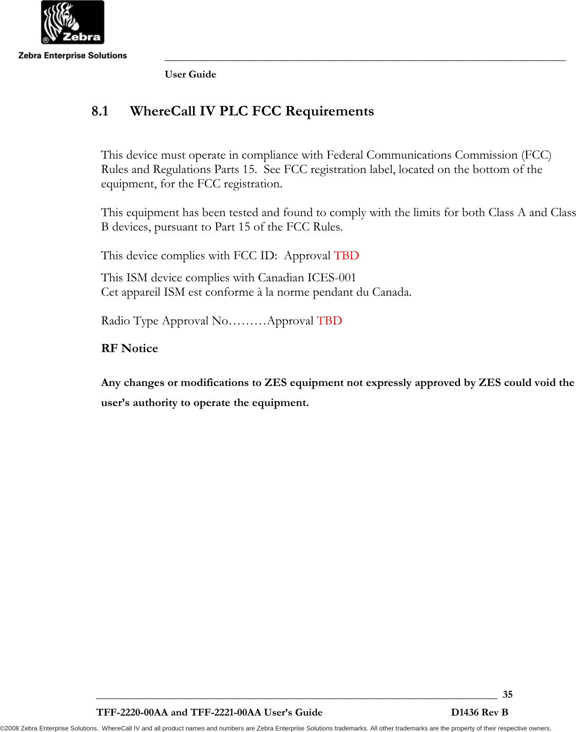
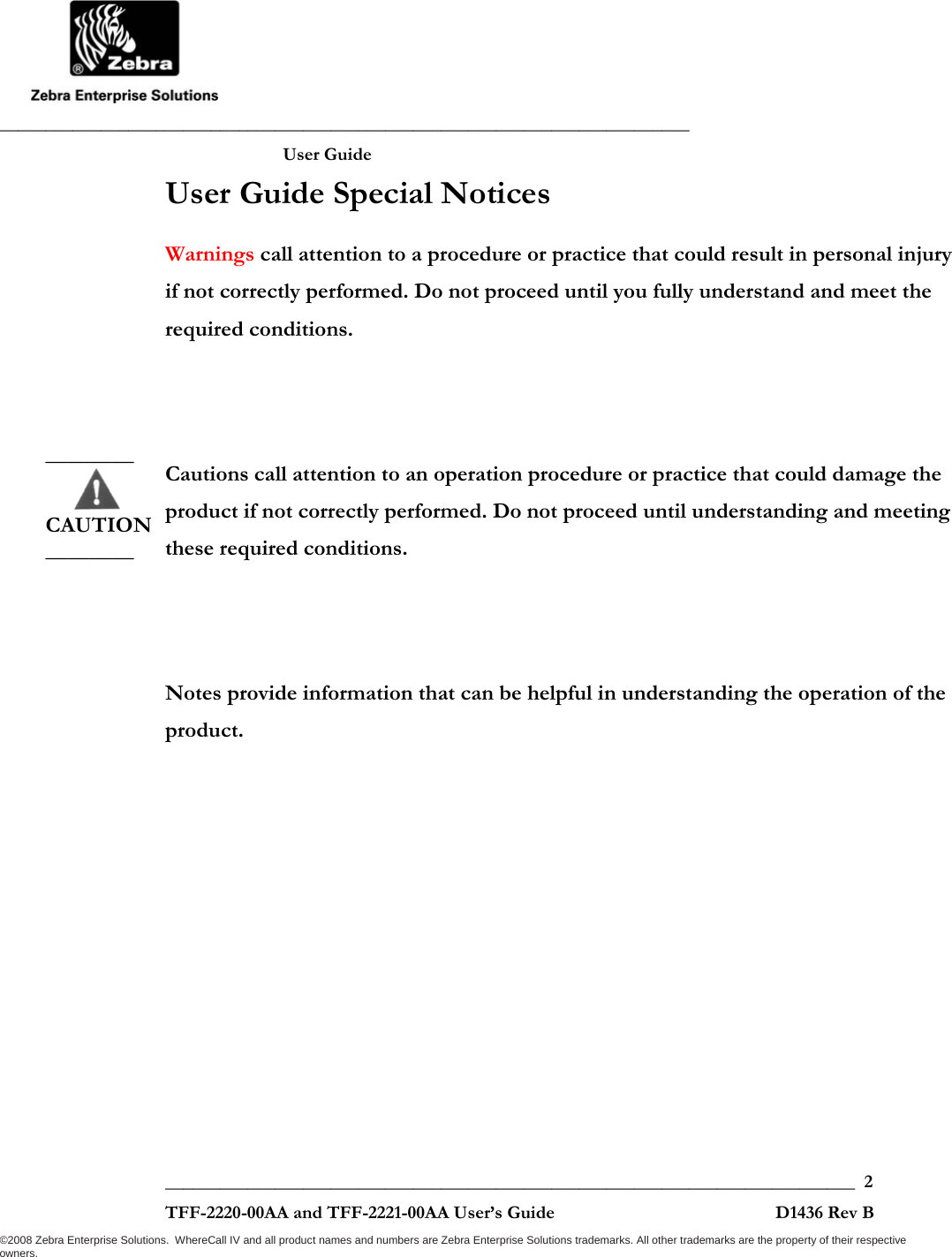
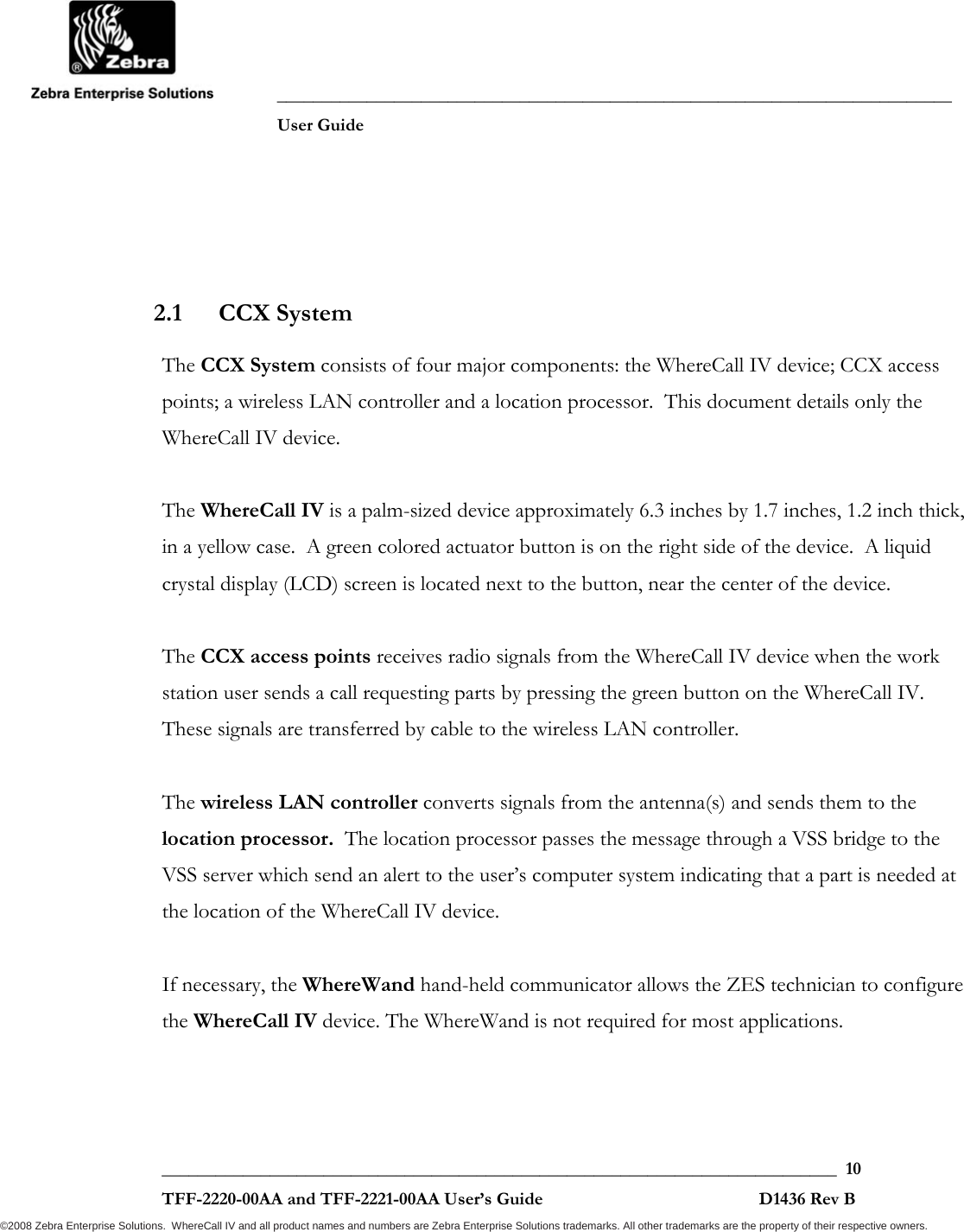
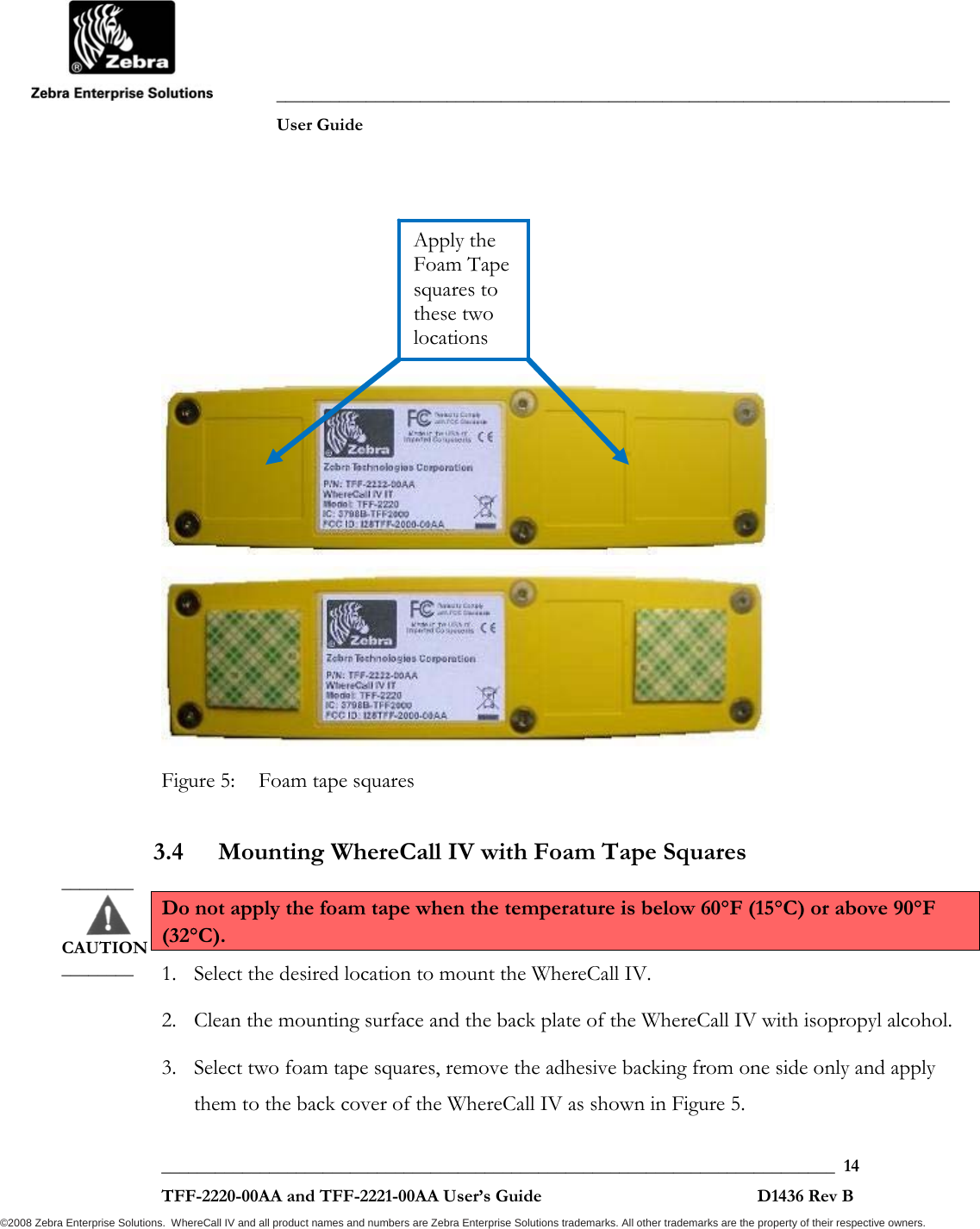
![___________________________________________________________________________ User Guide ___________________________________________________________________________ 18 TFF-2220-00AA and TFF-2221-00AA User’s Guide D1436 Rev B ©2008 Zebra Enterprise Solutions. WhereCall IV and all product names and numbers are Zebra Enterprise Solutions trademarks. All other trademarks are the property of their respective owners. 3.8 Installing WhereCall IV with Screw Mounting Bracket 1. Using a 5/64 inch hex drive bit, remove 4 screws from the bottom cover as shown in Figure 7. 2. Align the mounting bracket so the 4 screw holes align with the 4 screw holes in the WhereCall IV bottom cover. Be sure the four counter sunk holes in the mounting bracket are visible and not against the WhereCall IV bottom cover. Reinsert the screws through the bracket and into the bottom cover of WhereCall IV, with torque set to 6.0 + .6 inch-pounds [0.68 + 0.07 Newton-meters]. See figure 10. 3. Attach mounting bracket in the desired location using two screws or rivets through the counter sunk holes at the ends of the mounting bracket. The 0.188 inch [4.78 mm] diameter holes are spaced 7.0 inches apart. Figure 10: Screw Mounting Bracket Installed 7.0 inch [177.8 mm]](https://usermanual.wiki/Zebra-Technologies/TFF-2000-00AA.Users-Guide/User-Guide-1140560-Page-18.png)

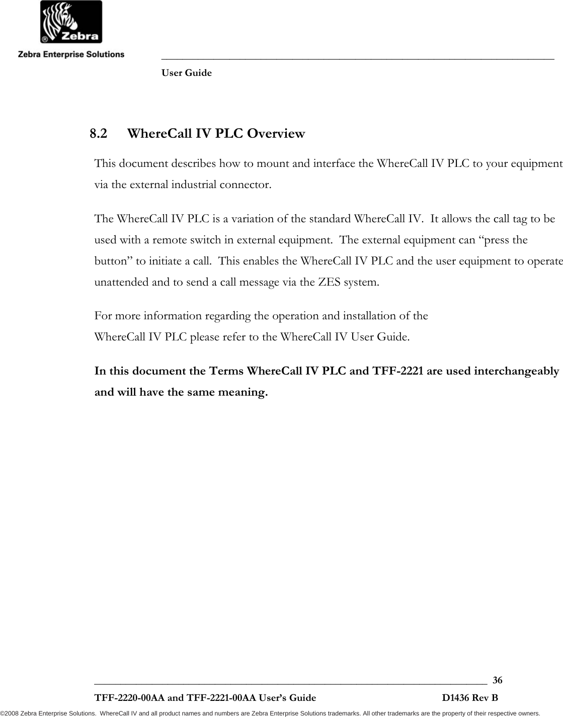
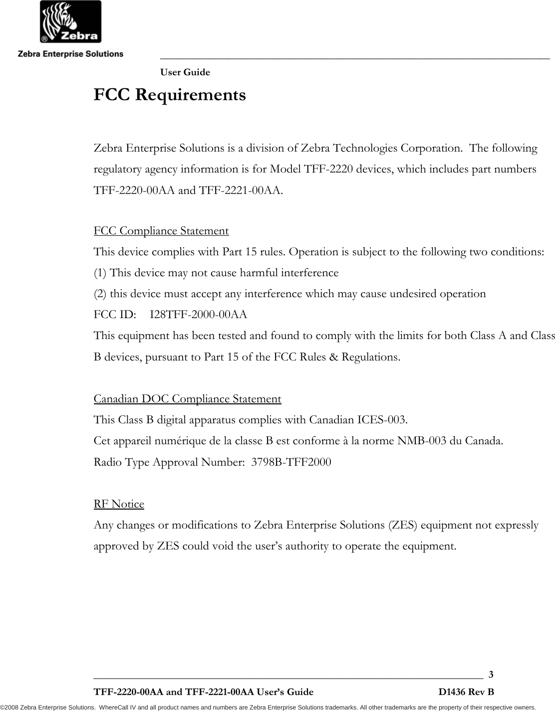
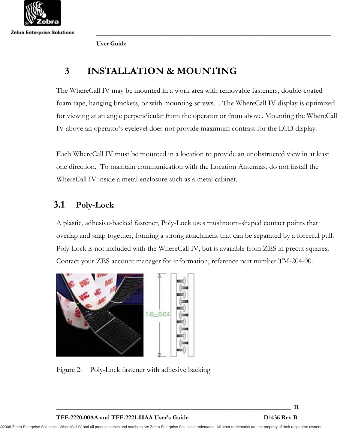
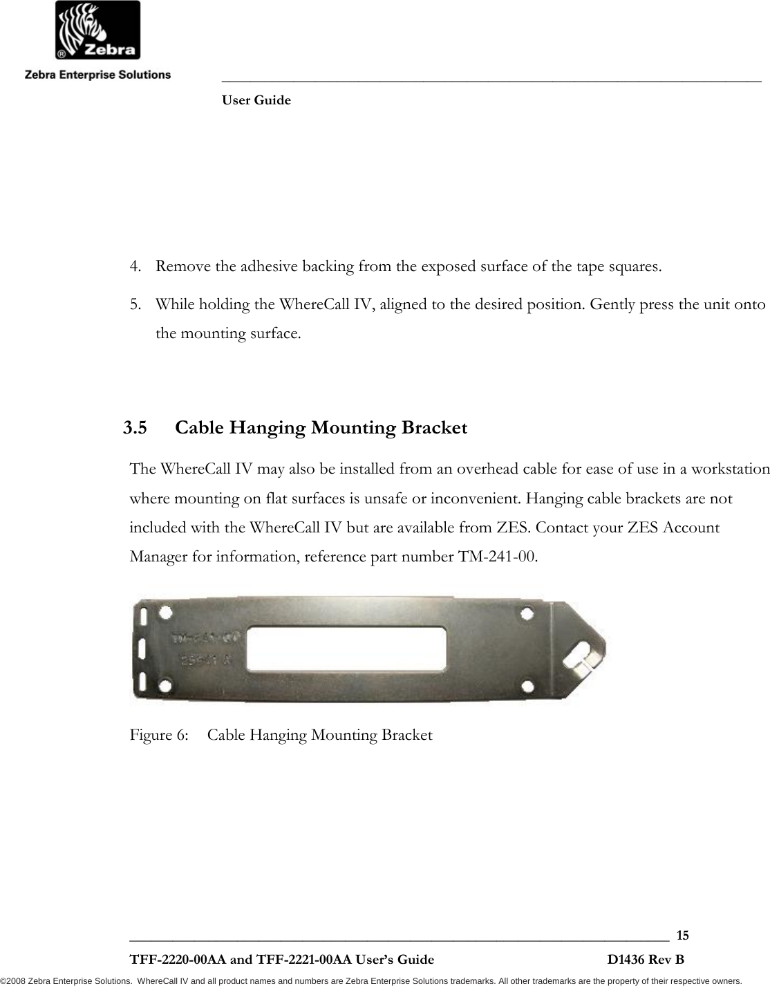
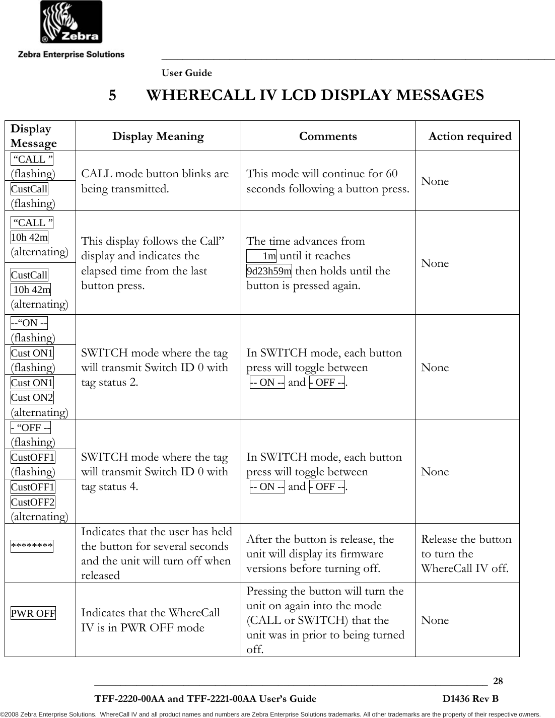
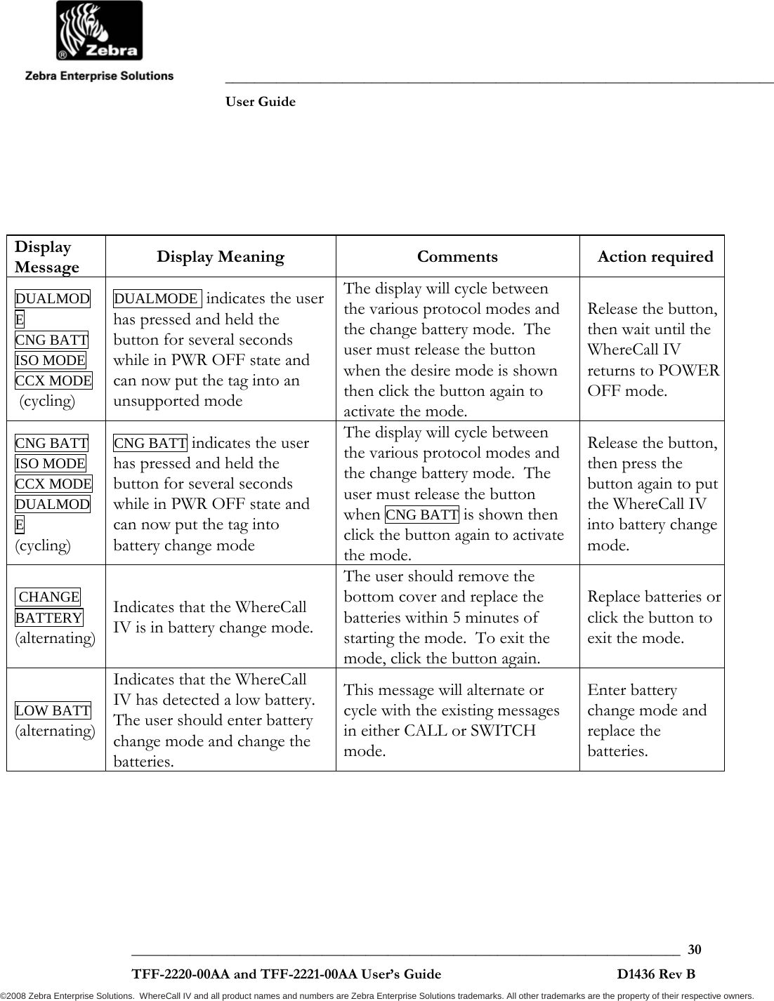
![___________________________________________________________________________ User Guide ___________________________________________________________________________ 26 TFF-2220-00AA and TFF-2221-00AA User’s Guide D1436 Rev B ©2008 Zebra Enterprise Solutions. WhereCall IV and all product names and numbers are Zebra Enterprise Solutions trademarks. All other trademarks are the property of their respective owners. 4.7.3 Tools ZES does not provide the required materials and tools for changing batteries with the WhereCall IV Tags. The following tools will be required to change the WhereCall IV batteries. • One, torque wrench with a 5/64 inch hex drive bit and the torque set to 6.0 + .6 inch-pounds [0.68 + 0.07 Newton-meters] for the six screws on the bottom cover of the tag. • One, “small, pocket size” flat blade screw driver use to remove batteries from the battery holder. • One, ESD wrist strap or equivalent static protection device. 4.7.4 Procedure To change the WhereCall IV batteries, the WhereCall IV must be in OFF mode and display PWR OFF . See section 4.3 for instructions on turning the WhereCall IV off. Step 1: Enter battery change mode as follows Press and hold the button for several seconds until the display starts to cycle between these options…ISO MODE, CCX MODE, DUALMODE, and CNG BATT. Release the button when the display shows CNG BATT, then click the button again to activate the mode. The WhereCall IV is now in a mode that draws more current in bursts to ensure the circuitry fully discharges when the batteries are removed. This mode will expire in 5 minutes, so the batteries should be replaced within 5 minutes to ensure proper restart of the internal processors. Step 2: Remove the 6 screws from the bottom cover of the WhereCall IV and remove the bottom cover and sealing gasket.](https://usermanual.wiki/Zebra-Technologies/TFF-2000-00AA.Users-Guide/User-Guide-1140560-Page-26.png)
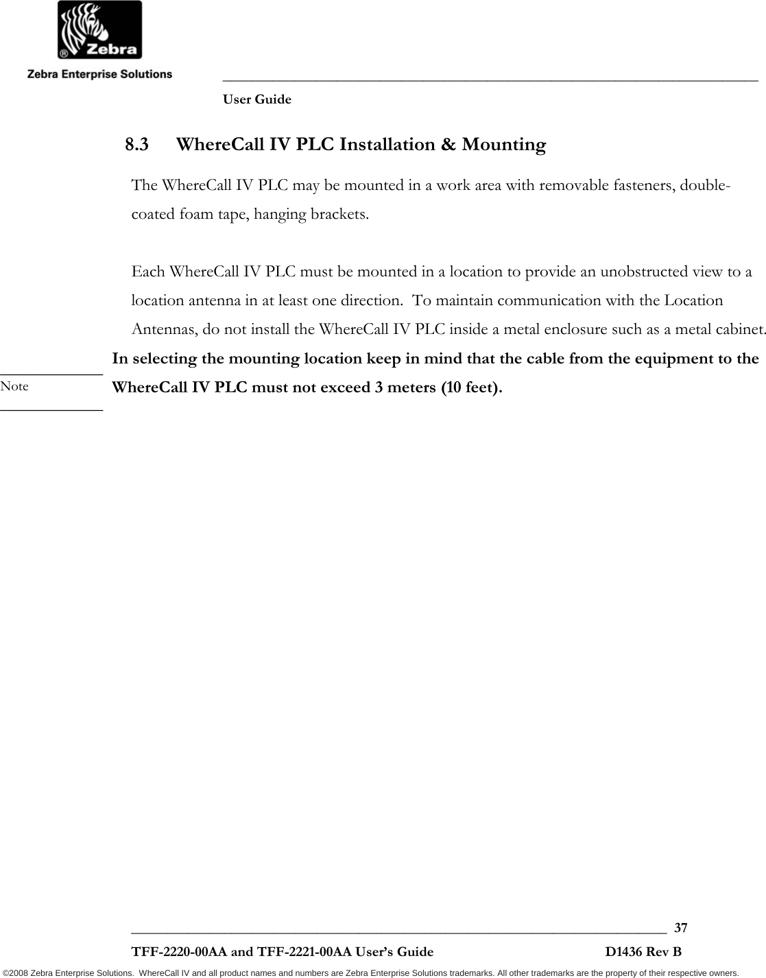
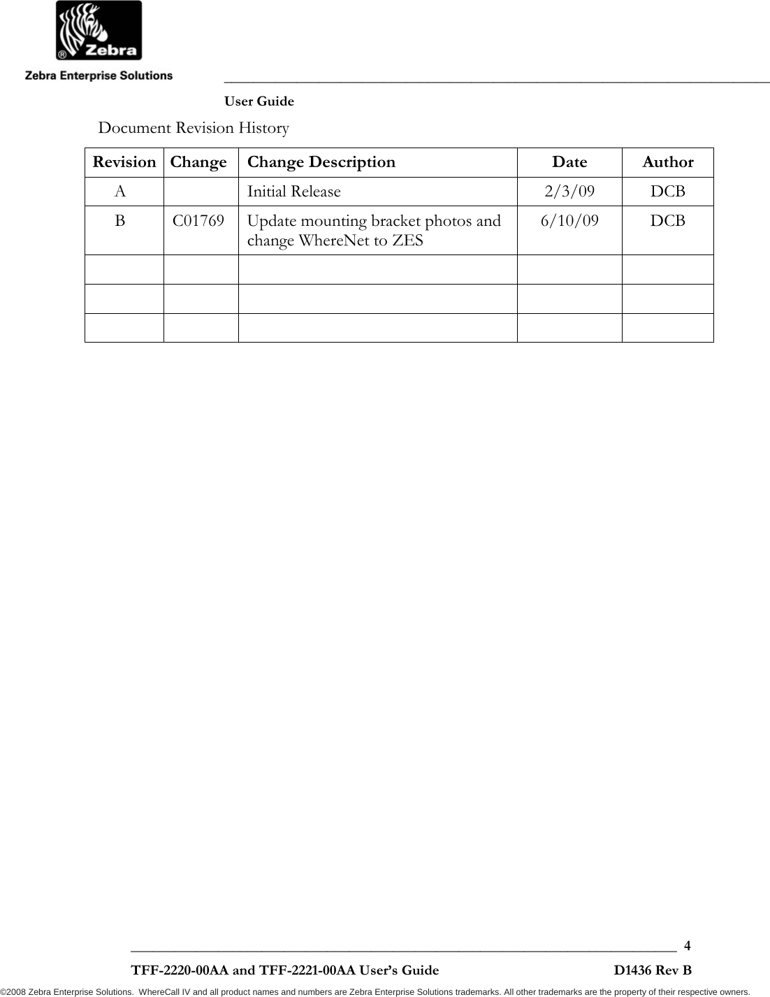
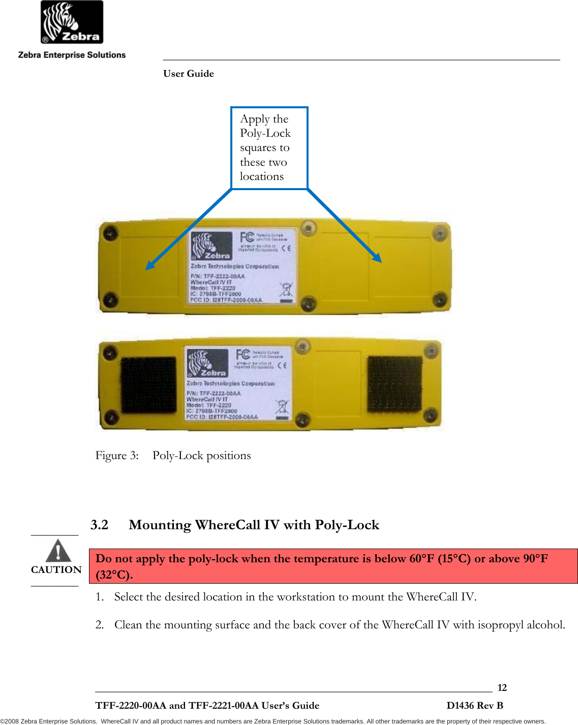
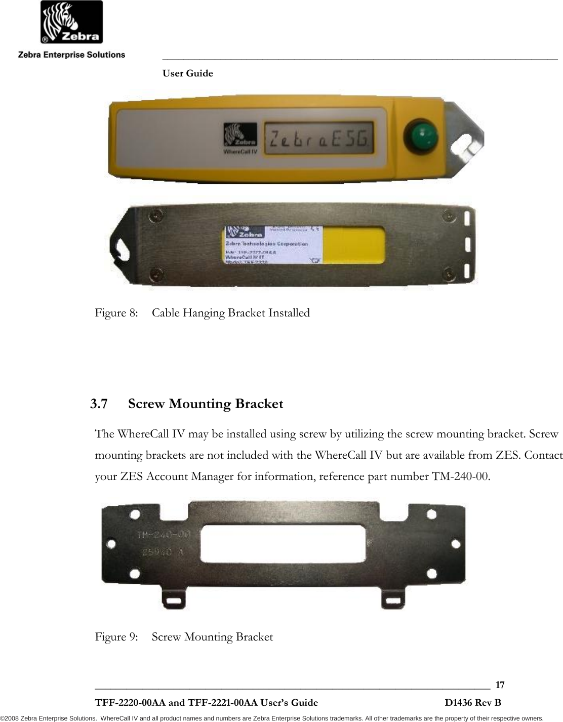
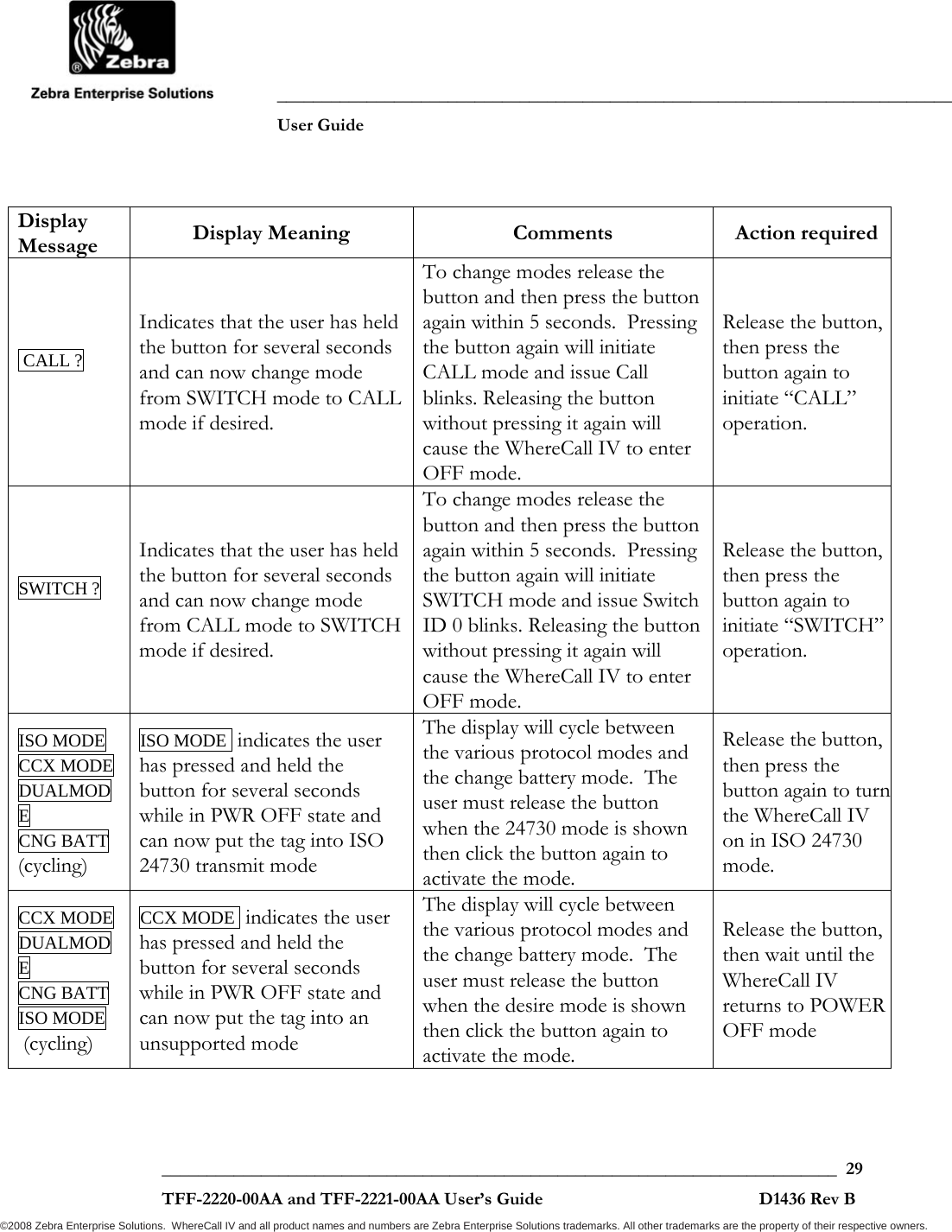
![___________________________________________________________________________ User Guide ___________________________________________________________________________ 27 TFF-2220-00AA and TFF-2221-00AA User’s Guide D1436 Rev B ©2008 Zebra Enterprise Solutions. WhereCall IV and all product names and numbers are Zebra Enterprise Solutions trademarks. All other trademarks are the property of their respective owners. Step 3: Remove both of the old batteries and dispose of properly. Step 4: Install two new batteries, being careful to orient the batteries correctly and not to install either battery backwards. Refer to figure 11 for proper battery orientation. Figure 11: Battery Replacement Caution: Inserting a battery with the wrong orientation may damage the tag. ZES assumes no responsibility for damage to or failure of the WhereCall Tags resulting from this battery replacement procedure. Step 5: Reattach the sealing gasket and the bottom cover with the 6 screws, and torque screws to 6.0 + .6 inch-pounds [0.68 + 0.07 Newton-meters]. Note battery orientation. The arrows point to the + side of the 2 batteries _________ CAUTION _________](https://usermanual.wiki/Zebra-Technologies/TFF-2000-00AA.Users-Guide/User-Guide-1140560-Page-27.png)
![___________________________________________________________________________ User Guide ___________________________________________________________________________ 31 TFF-2220-00AA and TFF-2221-00AA User’s Guide D1436 Rev B ©2008 Zebra Enterprise Solutions. WhereCall IV and all product names and numbers are Zebra Enterprise Solutions trademarks. All other trademarks are the property of their respective owners. 6 SPECIFICATIONS: WHERECALL IV DEVICE Specifications are subject to change without notice. Mechanical Dimensions 6.45 x 1.74 x 1.27 inches [163.8 x 44.2 x 32.3 mm] nominal Weight 6.3 ounces [180 grams] nominal Color High Visibility Yellow and Light Gray Attachments Mounting Brackets, Poly-Lock, or Foam Tape Form Factor Wall Mounted-Rugged Aesthetics Durability Drop 4 feet [1.22 meters] to concrete Temperature +0°F to +130°F, [ -20° to +55°C ] Operating -10°F to +140°F, [ -25° to +65°C ] Storage Humidity 0% to 95% condensing Dust and Water Resistant IP54 per IEC 60529 (dust and water spray tight) Button Functional for 1 million cycles ESD Functional per IEC-1000-4-2 Level 4 Operation not disrupted up to 8kV Unit not permanently damaged up to 15kV Battery Battery Type Two “AA” Lithium Thionyl Chloride Cells Battery Life Typical 5 years (Batteries are customer replaceable)](https://usermanual.wiki/Zebra-Technologies/TFF-2000-00AA.Users-Guide/User-Guide-1140560-Page-31.png)
![___________________________________________________________________________ User Guide ___________________________________________________________________________ 32 TFF-2220-00AA and TFF-2221-00AA User’s Guide D1436 Rev B ©2008 Zebra Enterprise Solutions. WhereCall IV and all product names and numbers are Zebra Enterprise Solutions trademarks. All other trademarks are the property of their respective owners. Connector (used with WhereCall IV PLC) Mating Connector Waterproof, 4 pin, mates with Turck RS-4.41T-X (where X is the cable length) or equivalent Display Characteristics Number of Characers 8 Format 14-Segment with apostrophe and decimal for each character Function Check previous page Digit Size .28 inch [7 mm] high Back Lit No Status Word Length 4 bits Battery low bit Bit 0 (---l) 0 = battery is OK l = low battery CALL mode Button Push or SWITCH mode = “ON” state Bit 1 (--1-) 0 = blink is not a switch blink, but a keep alive blink 1 = blink is CALL blink or SWITCH = ON blink SWITCH mode = “OFF” state Bit 2 (-1--) 0 = blink is not a switch blink, but a keep alive blink 1 = blink is SWITCH = OFF blink](https://usermanual.wiki/Zebra-Technologies/TFF-2000-00AA.Users-Guide/User-Guide-1140560-Page-32.png)