ZTE R8119F851719A Pico RRU User Manual Part 2
ZTE Corporation Pico RRU Part 2
UserManual.wiki
>
ZTE
>
R8119F851719A User Manual
>
User manual Part 2
Contents
1.
User manual Part 1
2.
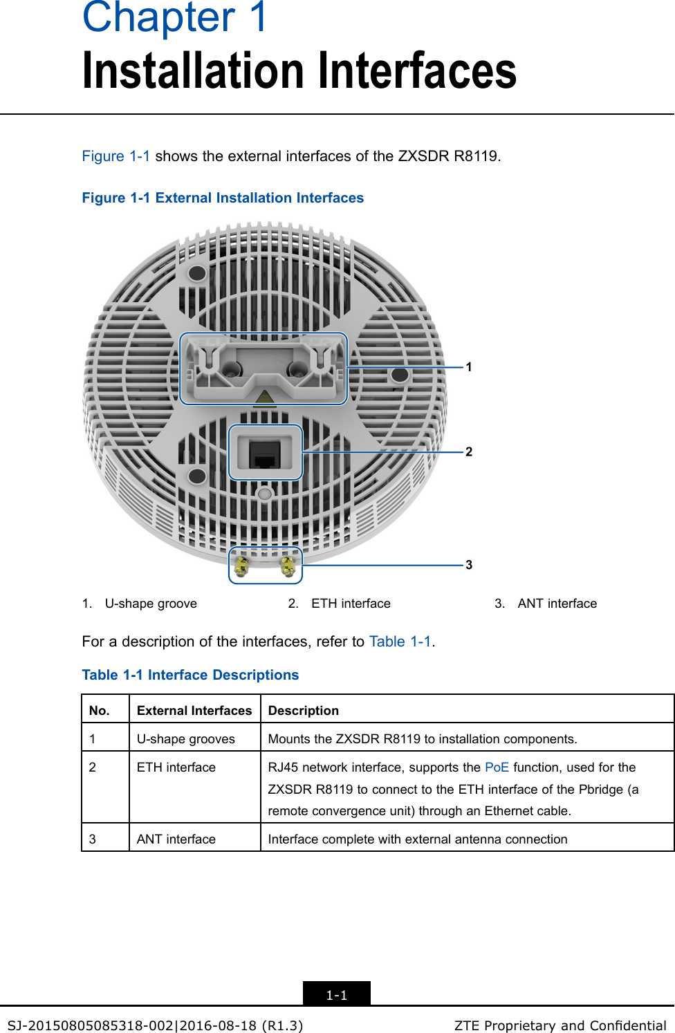
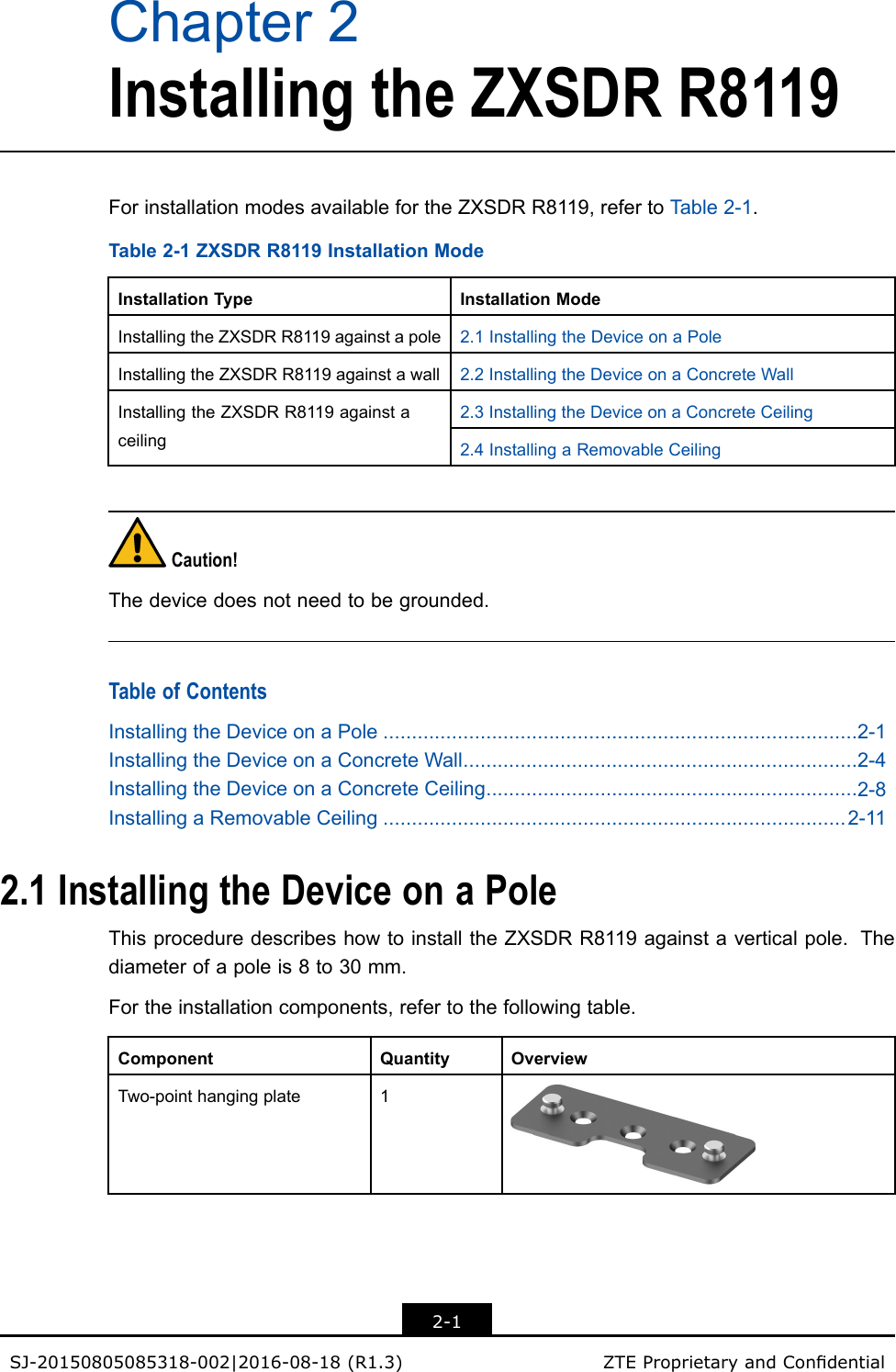
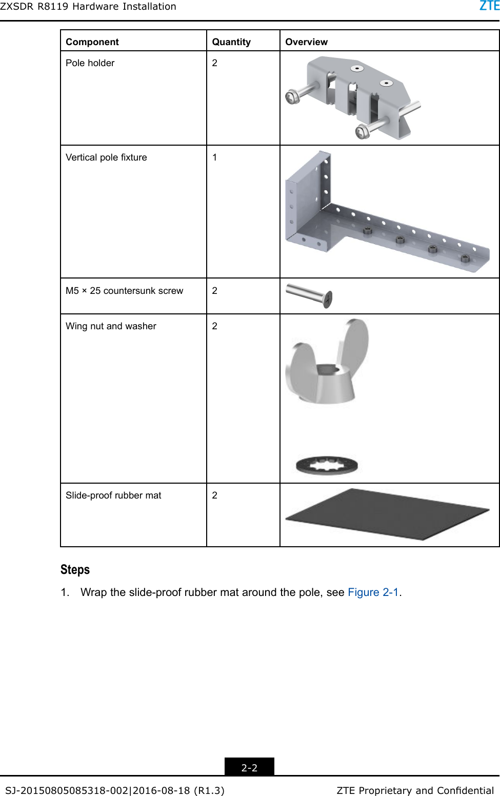
User manual Part 2
User manual Part 2
Navigation menu
Upload a User Manual
Namespaces
Wiki Guide
HTML
PDF
Info
Views
User Manual
Discussion / Help
Navigation