Yaesu Musen HX470SA Non-broadcast Transceiver Held to Face User Manual
Yaesu Musen Co., Ltd. Non-broadcast Transceiver Held to Face Users Manual
UserManual.wiki
>
Yaesu Musen
>
HX470SA User Manual
>
Manual Part 2
Contents
1.
Manual Part 1
2.
Manual Part 2
3.
Manual Part 3
Manual Part 2
Navigation menu
Upload a User Manual
Namespaces
Wiki Guide
HTML
PDF
Info
Views
User Manual
Discussion / Help
Navigation
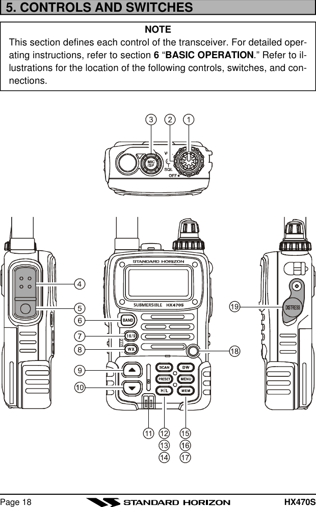
![HX470S Page 19POWER SWITCH/VOLUME CONTROLTurns the transceiver on and off, and adjusts the volume.SQUELCH (SQL) CONTROLSets the point at which random noise on the channel does not activatethe audio circuits but a received signal does. This point is called theSquelch threshold. Further adjustment of the squelch control will de-grade the reception of wanted transmissions.MIC/SP JACKThe jack accepts the optional CMP460 Speaker/Microphone, MH-57A4BMini Speaker/Microphone, or VC-24 VOX Headset. When this jack isused, the internal speaker is disabled.PUSH-TO-TALK (PTT) SWITCHWhen pushed activates the transmitter of the selected band.LAMP (KEY LOCK) KEYPress to turn the LCD and keypad backlighting on or off.Hold down this key to lock the keypad (except the PTT, LAMP, and [H/L]keys) so that they are not accidentally changed. The key lock symbol willappear on the LCD, to indicate that the functions are locked. Hold downuntil the key lock symbol disappears to unlock the radio.[BAND] KEYPress to select the VHF Marine, FRS , MURS , FM Broadcast, AM Broad-cast, and AIR (aircraft) bands.[16/9] KEYImmediately recalls channel 16 from any marine channel or band loca-tion. Holding down this key recalls channel 9.[WX] KEYImmediately recalls the last-used NOAA Weather Channel from any chan-nel location. Recalls the previously- selected working channel when the[WX] key is pressed again.Secondary use:When the [16/9] key is held and the [WX] key is pressed, the radio willchange the marine channel between the USA, International, and Cana-dian channels.](https://usermanual.wiki/Yaesu-Musen/HX470SA.Manual-Part-2/User-Guide-327066-Page-8.png)
![HX470SPage 20[p(UP)] KEYPress to select a desired channel. Each press increases the channelnumber. When held down, the channels increase continuously.[q(DOWN)] KEYPress to select a desired channel. Each press decreases the channelnumber. When held down, the channels decrease continuously.NMEA TERMINALConnect to GPS receiver that outputs NMEA sentences GLL, GGA, GNS,and RMC via the CD-25 Charger Cradle. Keep these terminals clean.[SCAN] KEYStarts scanning and priority scanning of programmed channels. Whenscanning, press and hold this key to turn on and off priority scan (P isshown on the left side of the display during Priority scanning).[PRESET] KEYImmediately recalls one of up to 10 user preset memories for each band(shown as P0-P9 on the LCD). Pressing this key repeatedly scrollsthrough the preset memory channels.[H/L] KEYOn the Marine Band, changes the transmitter output power between High(5 Watts), Medium (2.5 Watts), and Low (1 Watt). Does not operate on“Low power only,” Marine “transmission inhibit,” or FRS channels.[DW] KEYAutomatically scans between the priority channel and another selectedchannel (including FRS or a MURS channel). When receiving a signalon the selected channel the radio will dual watch to the priority channel.[MENU] KEYSelect the Marine Band then press to select the Setup mode. This modeallows features and functions to be changed.Refer to section 13. MENU (“SET”) MODE for additional information.](https://usermanual.wiki/Yaesu-Musen/HX470SA.Manual-Part-2/User-Guide-327066-Page-9.png)
![HX470S Page 21[MEM] KEYPress this key to memorize the selected channel for scanning. Whenpressed a “MEM” icon will be shown on the LCD display indicating thechannel has been saved to scan memory. The scan memory is onlyused with the Marine and WX channels.To delete the channel from scan memory, select the channel and pressthis key until “MEM” is removed from the display.BUSY/TX INDICATORThis indicator illuminates different colors depending on the band that isselected. The chart to the right showsthe colors illuminated with the Squelchcontrol fulluy counter clockwise or a sig-nal is received. This indicator glows redduring transmit.[DISTRESS] KEYWhen radio is programmed with a MMSI and this key is pressed onceand pressed and held again for 3 seconds the radio will transmit a DSCDistress Call. To send the distress call, see section 7.9 “DIGITAL SE-LECTIVE CALLING.”BAND COLORMARINE BlueFRS GreenMURS YellowAM/FM/AIR/MURS Marine Blue](https://usermanual.wiki/Yaesu-Musen/HX470SA.Manual-Part-2/User-Guide-327066-Page-10.png)