Yaesu Musen 30593X3D MOBILE MARINE TRANSCEIVER User Manual GX6000 Owner s Manual
Yaesu Musen Co., Ltd. MOBILE MARINE TRANSCEIVER GX6000 Owner s Manual
UserManual.wiki
>
Yaesu Musen
>
30593X3D User Manual
>
OM User Manual 10
Contents
1.
OM User Manual 1
2.
OM User Manual 2
3.
OM User Manual 3
4.
OM User Manual 4
5.
OM User Manual 5
6.
OM User Manual 6
7.
OM User Manual 7
8.
OM User Manual 8
9.
OM User Manual 9
10.
OM User Manual 10
OM User Manual 10
Navigation menu
Upload a User Manual
Namespaces
Wiki Guide
HTML
PDF
Info
Views
User Manual
Discussion / Help
Navigation
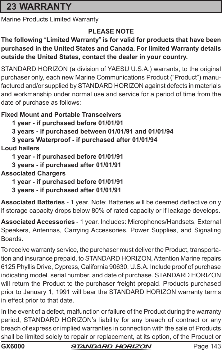
![Page 124 GX600018.9 NMEA 0183 IN/OUT18.9.1 Data SpeedThis menu is used to setup the NMEA 0183 baud rate of the GPS input (Blue and Green wires) and DSC output (Gray and Brown wires). The default setting is 4800 bps. When 38400 bps is selected the AIS sentences (VDM) and DSC sentences (DSC & DSE) both are output on the Gray and Brown wires after a DSC distress, position request or AIS transmission is received. 1. [] “SETUP” “GPS SETUP” “NMEA 0183 IN/OUT”2. Rotate the DIAL/ENT knob to select “DATA SPEED”, then press the [SELECT] soft key.3. Rotate the DIAL/ENT knob to select the desired speed from “4800bps” and “38400bps”.4. Press the [ENTER] soft key to save the new setting.5. Press the CLEAR key to return to radio operation.18.9.2 Output SentencesThis selection is used to setup the NMEA output sentences of the GX6000.By default, all the NMEA sentences are turned “ON”.1. [] “SETUP” “GPS SETUP” “NMEA 0183 IN/OUT”2. Rotate the DIAL/ENT knob to select “OUTPUT SENTENCES”, then press the [SELECT] soft key.3. Rotate the DIAL/ENT knob to select the desired sentence type, then press the [SELECT] soft key.](https://usermanual.wiki/Yaesu-Musen/30593X3D.OM-User-Manual-10/User-Guide-3702471-Page-1.png)
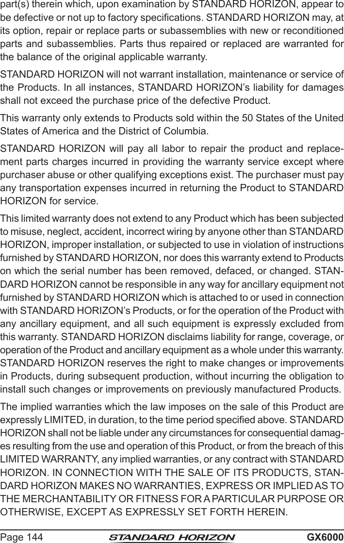
![Page 125GX60004. Rotate the DIAL/ENT knob to select “ON” or “OFF”.5. Press the [ENTER] soft key to save the new setting.6. Repeat steps 3 through 5 to set the other sentences.7. Press the CLEAR key to return to radio operation.NOTE• Data output will be performed based on the data acquisition order of priority congured from “ORDER OF PRIORITY”. Refer to section “18.1 ORDER OF PRIORITY” for details.• While “UNIT POWER” of “OPTION GPS UNIT” is set to OFF, NMEA sentences will not be output. (OPTION GPS reception data will be output as is.)• The output interval of each NMEA sentence depends on the output timing on the input device. However, sentences which include POS data will be output at intervals of two seconds or less.• When all sentences are set to be output, depending on the baud rate, not all sentences can be output at intervals of one second or less. GSA and GSV sentences will be output at intervals of around ve seconds.18.10 Position Data OutputSelect the connection device to be used when outputting position data.1. [] “SETUP” “GPS SETUP” “OPTION GPS UNIT”2. Rotate the DIAL/ENT knob to select “POS DATA OUTPUT”, then press the [SELECT] soft key.3. Rotate the DIAL/ENT knob to select “NMEA 2000” or “NMEA 0183”, then press the [SELECT] soft key.4. Rotate the DIAL/ENT knob to select “OFF” or “ON”.5. Press the [ENTER] soft key to store the new setting.6. Press the CLEAR key to return to radio operation.](https://usermanual.wiki/Yaesu-Musen/30593X3D.OM-User-Manual-10/User-Guide-3702471-Page-2.png)
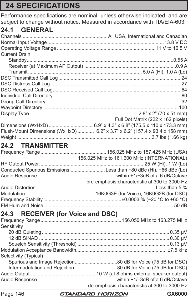
![Page 126 GX600018.11 OPTION GPS UNITChange the optional GPS Antenna (SCU-31) setting.18.11.1 Unit PowerWhen you use the SCU-31, set this selection to “ON”. The default setting is “OFF”.1. [] “SETUP” “GPS SETUP” “OPTION GPS UNIT”2. Rotate the DIAL/ENT knob to select “UNIT POWER”, then press the [SELECT] soft key.3. Rotate the DIAL/ENT knob to select “OFF” or “ON”.4. Press the [ENTER] soft key to store the new setting.5. Press the CLEAR key to return to radio operation.18.11.2 PinningThis selection is used to enable or disable position updates when the vessel is not underway. The default setting is “ON”.1. [] “SETUP” “GPS SETUP” “OPTION GPS UNIT”2. Rotate the DIAL/ENT knob to select “PINNING”, then press the [SELECT] soft key.3. Rotate the DIAL/ENT knob to select “OFF” or “ON”.ON: When pinning is turned on, the GX6000 will not update its position unless the ship’s speed over approximately 0.4 knot.OFF: When the vessel is underway or stopped, the GX6000 continuously updates its position. This improves accuracy of the position x.4. Press the [ENTER] soft key to save the new setting.5. Press the CLEAR key to return to radio operation.](https://usermanual.wiki/Yaesu-Musen/30593X3D.OM-User-Manual-10/User-Guide-3702471-Page-3.png)
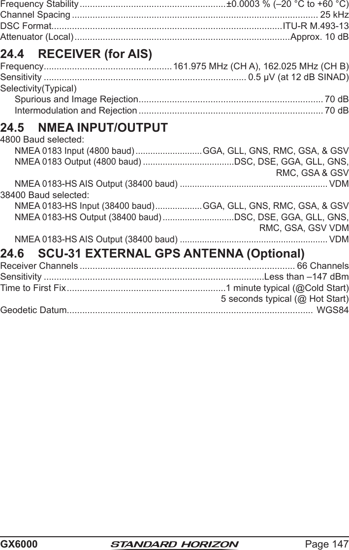
![Page 127GX600018.11.3 Differential GPS This selection enables or disables differential GPS function by SBAS (Satellite Based Augmentation System) such as WAAS, EGNOS and MSAS. In some areas (Australia for example), the GPS reception can have problems on enabling the SBAS. The default setting is “OFF”.1. [] “SETUP” “GPS SETUP” “OPTION GPS UNIT”2. Rotate the DIAL/ENT knob to select “DIFFERENTIAL GPS”, then press the [SELECT] soft key.3. Rotate the DIAL/ENT knob to select “OFF” or “ON”.4. Press the [ENTER] soft key to store the new setting.5. Press the CLEAR key to return to radio operation.18.11.4 Logger Interval1. [] “SETUP” “GPS SETUP” “OPTION GPS UNIT”2. Rotate the DIAL/ENT knob to select “LOGGER INTERVAL”, then press the [SELECT] soft key.3. Rotate the DIAL/ENT knob to select the desired time and press the [ENTER] soft key. Note: Log time for each logger interval setting15 sec: Aprox. 25 hours30 sec: Aprox. 50 hours1 min: Aprox. 100 hours2 min: Aprox. 200 hours5 min: Aprox. 500 hours4. Press the CLEAR key to return to radio operation.](https://usermanual.wiki/Yaesu-Musen/30593X3D.OM-User-Manual-10/User-Guide-3702471-Page-4.png)
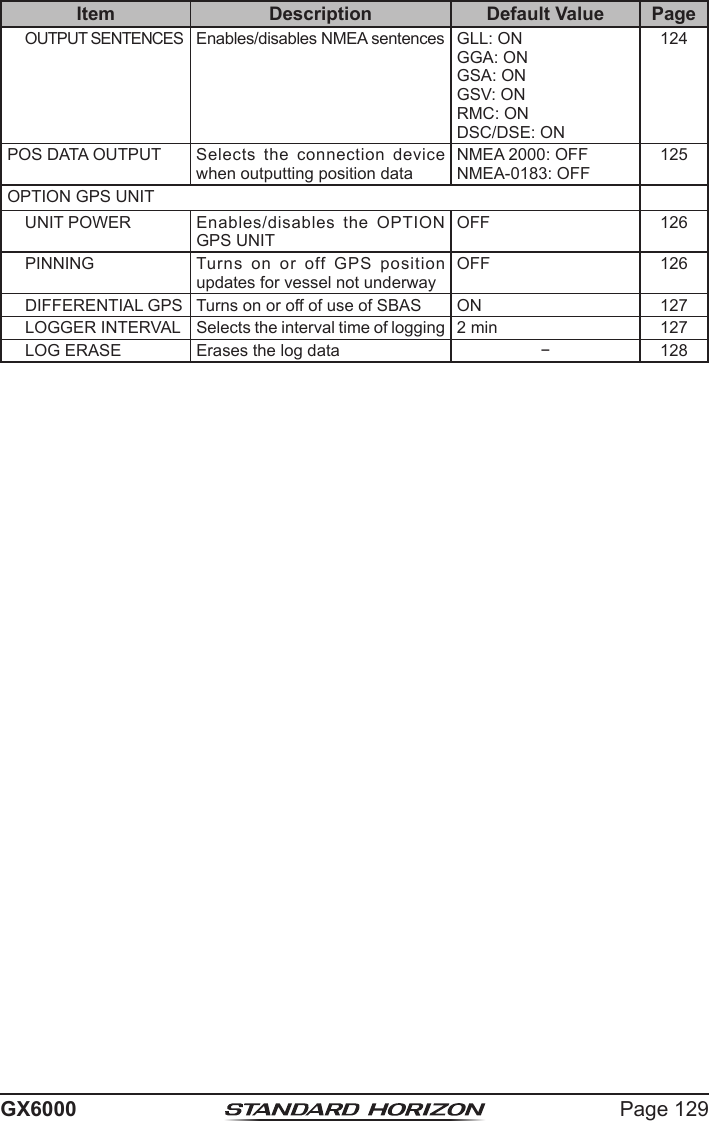
![Page 128 GX600018.11.5 Log Erase1. [] “SETUP” “GPS SETUP” “OPTION GPS UNIT”2. Rotate the DIAL/ENT knob to select “LOG ERASE”, then press the [SELECT] soft key.3. Press the [YES] soft key. (To cancel, press the [NO] soft key.)4. Press the [OK] soft key.5. Press the CLEAR key to return to radio operation.18.12 SUMMARY OF THE GPS SETUPItem Description Default Value PageORDER OF PRIORITY Sets the order of priority of the connection devices when obtaining position informationNMEA-0183 122COMPASS DIRECTION Selects the compass direction to be displayedCOURSE-UP 122LOCATION FORMAT Selects the coordinate system to be displayedddd°mm.mmmm 122TIME OFFSET Sets the offset time from the UTC (available only when “LOCAL” is selected in the item “TIME AREA”)00:00 123TIME AREA Selects the time location to be displayed, from UTC or local UTC 123TIME FORMAT Selects the time format to be displayed, 12-hour or 24-hour (fixed to “24H” when “UTC” is selected in the item “TIME AREA”) 24hour 123UNITS OF MEASURE Selects the unit if measure when displaying speed, distance, and altitudeSPEED: kts (knots)DISTANCE: nm (nautical mile)ALTITUDE: ft (feet)123MAGNETIC VARIATION Enables/disables the magnetic variation functionOFF 123NMEA 0183 IN/OUTDATA SPEED Sets the NMEA 0183 data speed 4800bps 124](https://usermanual.wiki/Yaesu-Musen/30593X3D.OM-User-Manual-10/User-Guide-3702471-Page-5.png)
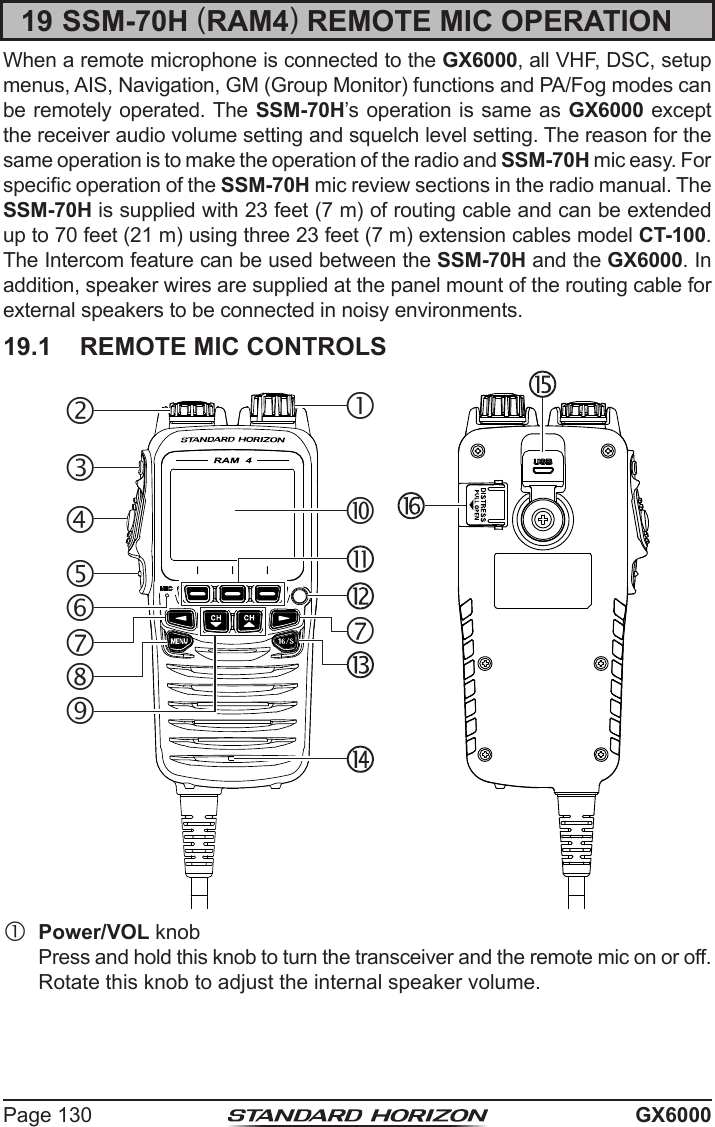
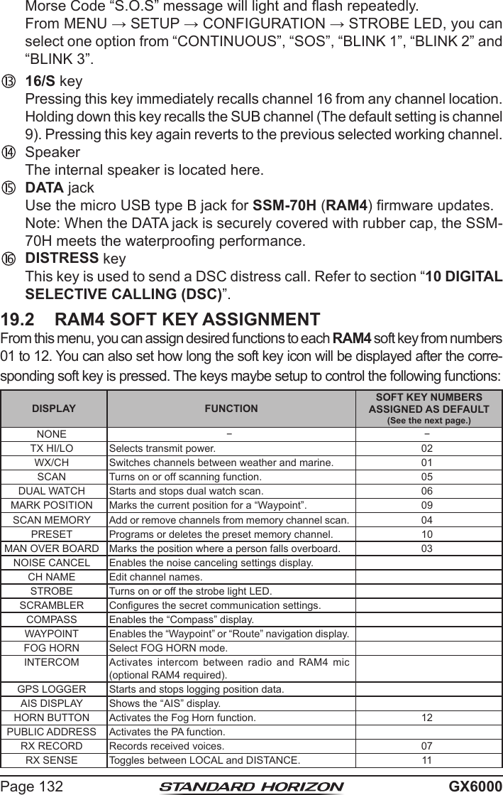
![Page 131GX6000 DIAL/ENT knob While the normal screen is displayed, rotate the DIAL/ENT knob to select your desired channel. While the MENU screen is displayed, rotate the knob to select your desired menu item. Secondary uSePress this knob to enter a selection in the MENU. SQL key (Squelch control) Press this key to activate the squelch adjusting mode. Press the CH▲ or CH▼ key to adjust the squelch threshold level. PTT (Push-To-Talk) switch Push this switch to enable the transmitter. CLEAR/ key Press this key to cancel a menu selection. Press and hold this key to acti-vate the key lock function. Press and hold this key again to deactivate the key lock function. Microphone The internal microphone transmits your voice reducing background noise using Clear Voice Noise Reduction Technology. Note: Position your mouth about 1/2” (1.5 cm) away from the microphone hole and speak in a normal voice. ◄/► key Press these keys to switch the function of soft keys Secondary uSe While the MENU screen is displayed, press the key to slide the on-screen menu to the right/left side. MENU key Press this key to access the MENU. CH▼/CH▲ key These keys are used to change the operating channel. Press the key momentarily, the channel increases/decreases one step. Holding the key, the channel increases/decreases continuously. Secondary uSe While the MENU screen is displayed, press the key to slide the on-screen menu upward/downward. When in the PA or Fog mode, press the key to change the channel. Display Full dot matrix display, 222 by 162 pixels. Soft keys These three programmable keys can be customized through the setup menu mode. When pressing one of these keys briey, the key functions will appear at the bottom of the display. Refer to section “19.2 RAM4 SOFT KEY ASSIGNMENT” for details. Strobe Light When the [STROBE] soft key is pressed, the internationally-recognized](https://usermanual.wiki/Yaesu-Musen/30593X3D.OM-User-Manual-10/User-Guide-3702471-Page-8.png)
![Page 133GX6000DISPLAY FUNCTIONSOFT KEY NUMBERS ASSIGNED AS DEFAULT (See the next page.)PLAY Plays recorded voices. 08NOTEYou can assign functions to soft keys on each of the transceiver and the optional SSM-70H (RAM4) remote mic.19.2.1 Key AssignmentCongure all settings on the SSM-70H (RAM4) remote mic for which you want to assign functions to soft keys.1. [] “SETUP” “CONFIGURATION” “SOFT KEY”2. Rotate the DIAL/ENT knob to select “KEY ASSIGN-MENT”, then press the [SELECT] soft key.3. Rotate the DIAL/ENT knob to select the key number to be programmed, and press the [SELECT] soft key. 4. Rotate the DIAL/ENT knob to select a new function to be assigned, and press the [ENTER] soft key. Avail-able functions are listed below. By selecting “NONE” the soft key assignment is removed.5. Repeat steps 3 and 4 to program other soft keys. Up to 24 functions can be assigned. The VHF radio's functions can be assigned to the maximum of 12 soft keys. Pressing the ►/◄ key each time shows three different soft keys.01 04 1002 05 1103 06 1207 08 09(The illustration above is the default setting.)6. Press the CLEAR/ key to return to radio operation.](https://usermanual.wiki/Yaesu-Musen/30593X3D.OM-User-Manual-10/User-Guide-3702471-Page-10.png)