Yaesu Musen 30393X20 HANDHELD VHF MARINE LAND MOBILE RADIO User Manual HX400 pmd
Yaesu Musen Co., Ltd. HANDHELD VHF MARINE LAND MOBILE RADIO HX400 pmd
UserManual.wiki
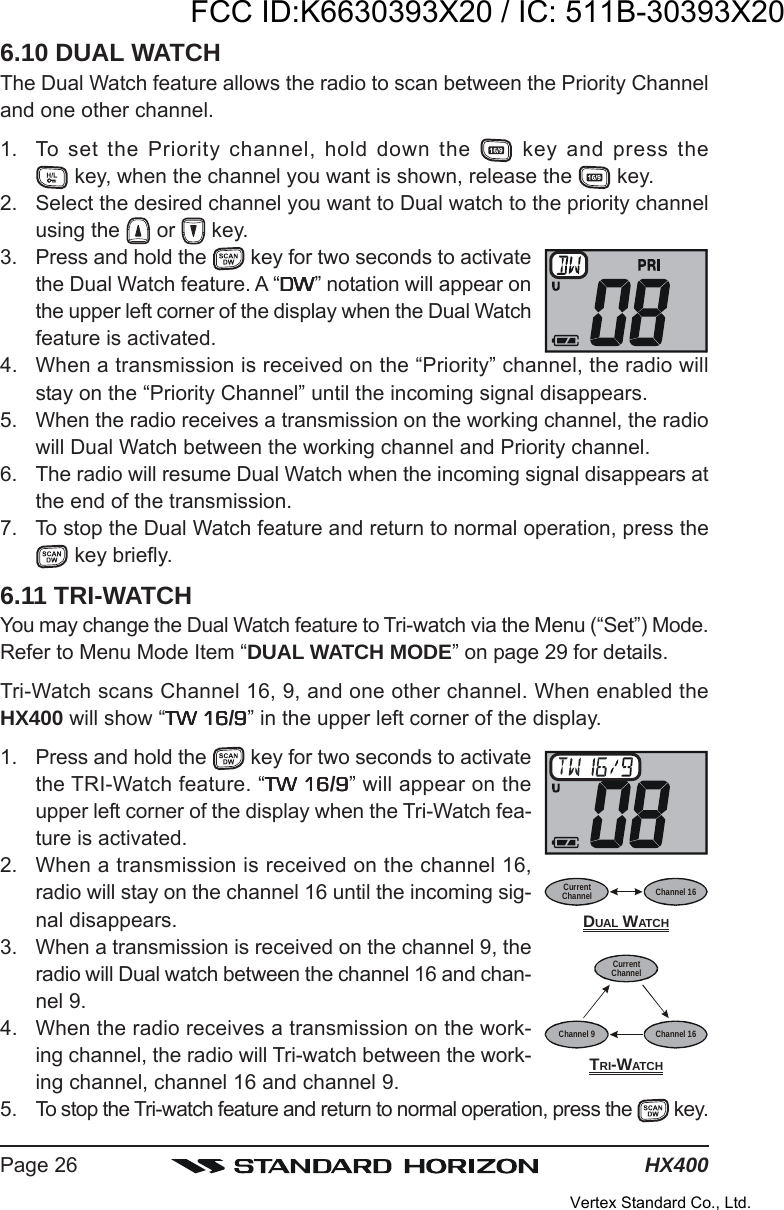
>
Yaesu Musen
>
30393X20 User Manual
>
Users Manual
Contents
1.
Users Manual
2.
User Manual
Users Manual
Navigation menu
Upload a User Manual
Namespaces
Wiki Guide
HTML
PDF
Info
Views
User Manual
Discussion / Help
Navigation
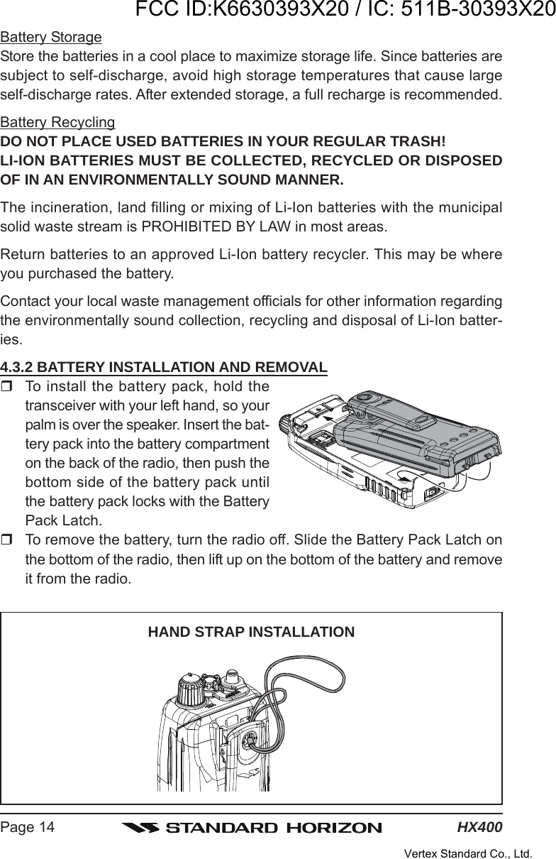
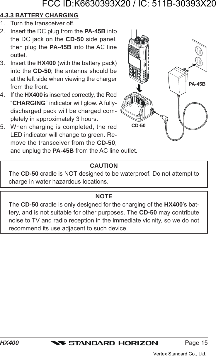
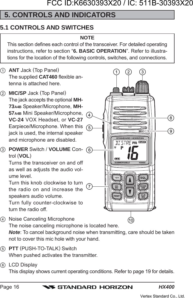
![Page 3HX400QUICK REFERENCE GUIDEThis transceiver is equipped with the E2O (Easy-To-Operate) system. You cando the basic operation in numerical order of the illustration below. [PWR/VOL] KNOBRotate this knobclockwise to turn onthe radio, and adjustthe audio level. [SQL] BUTTONPress this key first,then press the []key to squelch orpress the [] key toun-squelch the radio. []/[] BUTTONSSelects the operatingchannel.MICWhen transmitting,position your mouth1 inch (2.5 cm) awayfrom the small michole.Speak slowly andclearly into the micro-phone. [16/9] BUTTONPress to recallchannel 16.Press and hold torecall channel 9. [H/L()] BUTTONPress to toggle thetransmit power be-tween High (5W) andLow (1W). [PTT] SWITCHSpeak into the micro-phone in a normalvoice level whilepressing this switch.NOTEFor additional details, refer to next page or section “5. CONTROLS ANDINDICATORS”.FCC ID:K6630393X20 / IC: 511B-30393X20Vertex Standard Co., Ltd.](https://usermanual.wiki/Yaesu-Musen/30393X20.Users-Manual/User-Guide-1390848-Page-3.png)