Yaesu Musen 20663X20 AMATEUR HANDHELD VHF RADIO - SCANNING RECEIVER User Manual OM
Yaesu Musen Co., Ltd. AMATEUR HANDHELD VHF RADIO - SCANNING RECEIVER OM
UserManual.wiki
>
Yaesu Musen
>
20663X20 User Manual
>
User Manual 2
Contents
1.
User Manual 1
2.
User Manual 2
3.
User Manual 3
User Manual 2
Navigation menu
Upload a User Manual
Namespaces
Wiki Guide
HTML
PDF
Info
Views
User Manual
Discussion / Help
Navigation
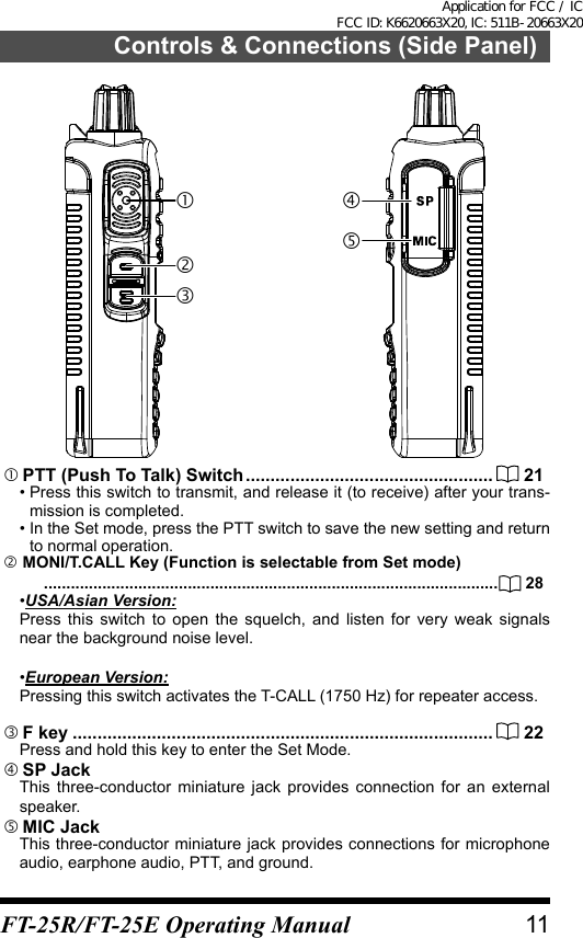
![Controls & Connections (Keypad)Key Primary Function(PRESS Key)Secondary Func-tion(PRESS F + Key)Third Function(Press and Hold Key)Frequency entry digit “1” ―Recalls the “Weather” broadcastchannel bankFrequency entry digit “2” ―Activates the ARTS featureFrequency entry digit “3” ― ―Frequency entry digit “4” ― ―Frequency entry digit “5” ― ―Frequency entry digit “6” ―Key Lock featureFrequency entry digit “7” ― ―Frequency entry digit “8” ― ―Frequency entry digit “9” ― ―Frequency entry digit “0” ― ―*1recalls the stored orassigned settingHOME (Fixed setting)store or assign asetting to the keyTX PWR (Fixed setting)FM radioREV (Fixed setting)recalls the Memory Mode and activates the “Memory “Tune” Mode while in the Memory Mode.Activates the Priori-ty function Memory write modeSwitches VFO-A and VFO-BPMS(Program Mem-ory (Mode) Scan)Program Scan Setting*1 : When entering a frequency from the keypad, there is a short-cut for frequencies ending in zero - after the last non-zero digit, press and hold the [0/SET] key to enter all the zeros at once.14 FT-25R/FT-25E Operating ManualApplication for FCC / IC FCC ID: K6620663X20, IC: 511B-20663X20](https://usermanual.wiki/Yaesu-Musen/20663X20.User-Manual-2/User-Guide-3244130-Page-4.png)
![Basic OperationTurn the Power ON and OFF• Be sure the Battery Pack is installed, and is fully charged. Connect the antenna to the top panel Antenna jack.• Rotate the PWR/VOL knob out of the click-stop to turn the transceiver ON. The current DC supply voltage will be shown on the display for two seconds. After the two second interval, the display will commence the normal operating fre-quency indication.• To turn the transceiver OFF, turn the PWR/VOL knob fully counter-clock-wise into the click-stop position.Adjust the Audio Volume Level and Squelch SettingRotate the PWR/VOL knob to adjust the receiver volume. Listen to the open squelch background noise to adjust the audio to a comfortable level.1. To set the squelch level, press the F key and then press the MONI/T.CALL key, to open the SQ LEVEL set mode.2. Press the [] or [] key to adjust to a level at which the background noise is muted.3. Press the PTT switch to save the squelch setting and return to normal operation.Changing between VFO-A and VFO-B• Press the [#VFO] key repeatedly to toggle the frequency control between the VFO mode and the Memory mode.• Frequency ranges are shown in the table.Frequency RangeRX TXUSA model 137-174 MHz 144-148 MHzEuropean model 137-174 MHz 144-146 MHzAsian model 137-174 MHz 136-174 MHz19FT-25R/FT-25E Operating ManualApplication for FCC / IC FCC ID: K6620663X20, IC: 511B-20663X20](https://usermanual.wiki/Yaesu-Musen/20663X20.User-Manual-2/User-Guide-3244130-Page-9.png)
![Frequency NavigationThe FT-25R/E will initially be operating in the “VFO” mode. The VFO permits free tuning throughout the currently-selected operating band in designated frequency steps (operating channels).Three basic frequency navigation methods are provided on the FT-25R/E:1) Tuning FrequencyPressing the [] key tunes the FT-25R/E toward a higher frequency, while pressing the [] key will lower the operating frequency, in steps prepro-grammed for the current operating band.2) Direct Keypad Frequency EntryThe operating frequency may be entered directly from the keypad by press-ing the numbered digits on the keypad in the proper sequence. Examples: To enter 145.560 MHz, press [1] [4] [5] [5] [6] [0] To enter 145.000 MHz*, press [1] [4] [5] [0] [0] [0] *There is a short-cut to enter frequencies ending in zeros - after the last non-zero digit, press and hold the [0/SET] key to enter the remaining zeros.3) ScanningManual VFO Scan:To manually initiate VFO scanning, press and hold either the [] or [] key to begin upward or downward scanning, respectively.Programmed Mode VFO Scan:To begin scanning within a limited sub-band range from the VFO mode, press and hold the [#VFO] key to select the bandwidth for the Pro-grammed Mode (VFO) scanner. Then press the F key and the [#VFO] key to start scanning.The scanner will stop when it receives a signal strong enough to open the Squelch threshold.(Manual VFO Scan)(Programmed Mode VFO Scan)The FT-25R/E will then hold on that frequency in accordance with the “RE-SUME” mode setting (Set Mode Item “25 RESUME”).Press the PTT switch momentarily to cancel the scanning (this only stops the scan; it does not cause a transmission to occur).20Basic OperationFT-25R/FT-25E Operating ManualApplication for FCC / IC FCC ID: K6620663X20, IC: 511B-20663X20](https://usermanual.wiki/Yaesu-Musen/20663X20.User-Manual-2/User-Guide-3244130-Page-10.png)
![The direction of the scan may not reverse while FT-25R/E is scanning.For more details on the scanning, see page 35.Transmission• To transmit, press the PTT switch, and speak into the front panel micro-phone (located in the lower left-hand corner of the speaker grille) in a nor-mal voice level. The TX/BUSY indicator will glow red during transmission.• To return to the receive mode, release the PTT switch.• During transmit, the power level will be indicated relatively on the bar graph at the bottom of the LCD. Full scale deection conrms “High Pow-er” operation. Five bars indicate “Medium Power” operation, while one bar indicates “Low Power” operation. Additionally, while operating on the “Low Power” or “Medium Power” setting, the “ ” icon or “ ” icon will appear at the bottom-left of the display.Changing the Transmit Power LevelTo change the power level:1. Press the F key and then press the [P2] key.• The present TX power output level will appear on the display.• To adjust the TX power in the Set Mode, press and hold the F key.Then repeatedly press the [▲] or [▼] key to select Set Mode item “32 TX PWR” and then press the F key.2. Press the [▲] or [▼] key to select the desired power output level.Available selections are “HI ” (5 W), “MID” (2.5 W), and “LOW” (0.5 W).3. Press the PTT switch to save the new setting and return to normal oper-ation.21Basic OperationFT-25R/FT-25E Operating ManualApplication for FCC / IC FCC ID: K6620663X20, IC: 511B-20663X20](https://usermanual.wiki/Yaesu-Musen/20663X20.User-Manual-2/User-Guide-3244130-Page-11.png)
![Activating the Set ModeUse the following procedure to activate the Set Mode and configure the transceiver parameters.1. Press and hold the F key to enter the Set Mode.2. Repeatedly press the [▲] or [▼] key to select the Set Mode Item to be adjusted.3. Press the F key momentarily to enable adjustment of the Set Mode Item.4. Press the [▲] or [▼] key to adjust the level, or choose the parameter, of the selected Set Mode Item.5. After completing the selection and adjustment, press the PTT switch to save the new setting and exit to normal operation.Setting the Quick Recall KeysThe four keys (P1, P2, P3 & P4), are user pro-grammable. The four keys are assigned as shown in the table:Quick Recall Key Press Press after pressing F key Press and holdrecall the stored or assigned settingHOME (Fixed setting)store or assigna setting to the keyTX PWR (Fixed setting)SQL TYPE (Fixed setting)REV (Fixed setting)Assigning Set Mode Items to the Quick Recall Keys (Set Mode Recall feature)1. Press and hold the F key to enter the Set Mode.2. Press the [▲] or [▼] key to select the Set Mode Item to be assigned to the quick recall key as a recalled Menu item.The quick recall keys can store and recall favorite frequen-cy settings, and are also short-cut keys to the Set Mode menu items.3. Press and hold the [P1], [P2], [P3] or [P4] key to assign the Set Mode Item to the quick recall key.4. Press the [P1], [P2], [P3] or [P4] key to recall the assigned Set Mode Item.22Basic OperationFT-25R/FT-25E Operating ManualApplication for FCC / IC FCC ID: K6620663X20, IC: 511B-20663X20](https://usermanual.wiki/Yaesu-Musen/20663X20.User-Manual-2/User-Guide-3244130-Page-12.png)
![Storing the displayed Frequency and Settings to a Quick Recall Key (Quick Memory feature)1. While operating in the VFO mode or the Memory mode, set the desired frequency and associated settings.2. Press and hold the [P1], [P2], [P3] or [P4] key to store the frequency and settings to a Programmable key.3. Press the [P1], [P2], [P3] or [P4] key to recall the stored settings.A Quick recall key may also store the frequency and asso-ciated settings in the Memory Mode.Setting the Preferred Operating ModeThe following reset or preferred operating modes may be selected.Display DescriptionF1:SET RESET Reset the Set Mode settings to factory defaults.F2:MEM RESET Clear the Memory settings to factory defaults.F3:BANK RESET Clear the Memory Bank assignments.F4:ALL RESET Clear the All memories and other settings to factory defaults.F5:MEM-ONLY Operation on the Memory mode only.F6:VHF-ONLY Operation on the VHF Band only.F7:FM-ONLY Operation on the FM Band only.F8 CLONE Clone mode.1. Turn the transceiver OFF.2. Press and hold the MONI/T.CALL key and the PTT switch simultaneously, while turning the radio ON.3. When the LCD backlight comes on, release the MONI/T.CALL key and PTT switch.4. Referring to the above table, press the [▲] or [▼] key to select the desired operating mode.5. Press the F key momentarily to activate the selected operating mode.23Basic OperationFT-25R/FT-25E Operating ManualApplication for FCC / IC FCC ID: K6620663X20, IC: 511B-20663X20](https://usermanual.wiki/Yaesu-Musen/20663X20.User-Manual-2/User-Guide-3244130-Page-13.png)
![Advanced OperationAfter becoming familiar with the basic operations of the FT-25R/E, you will want to learn about some of the really handy operating and convenience fea-tures.Turning the Keylock Feature ON and OFFThe FT-25R/E keypad may be locked to prevent accidental frequency change or inadvertent transmissions,1. Press and hold the [6] key to lock the keys and switches.•The icon will appear on the LCD display.•To unlock, press and hold the [6] key again.Change the key locking schemeThe following locking schemes may be selected.Display DescriptionKEY(default setting) Just the front panel keypad is locked out.PTT The PTT switch is locked out (TX not possible).P+K Both the PTT switch and the keypad are locked out.1. Press and hold the F key to enter the Set Mode.2. Press the [▲] or [▼] key to select Set Mode Item “15 KEY LOCK”.3. Press the F key momentarily to enable adjustment of this Item.4. Press the [▲] or [▼] key to choose one of the above listed locking schemes.5. Press the PTT switch to save the new setting and return to normal oper-ation.Change the LCD and keypad back light settingDisplay Description5secKEY (default setting) Keypad and LCD Lamp lights for 5sec.10secKEY Keypad and LCD Lamp lights for 10sec.30secKEY Keypad and LCD Lamp lights for 30sec.CONT Keypad and LCD Lamp lights continually.OFF Disable the Keypad and LCD Lamp function.1. Press and hold the F key to enter the Set Mode.2. Press the [▲] or [▼] key to select Set Mode item “16 LAMP”3. Press the F key to enable adjustment of this Item.24 FT-25R/FT-25E Operating ManualApplication for FCC / IC FCC ID: K6620663X20, IC: 511B-20663X20](https://usermanual.wiki/Yaesu-Musen/20663X20.User-Manual-2/User-Guide-3244130-Page-14.png)
![4. Press the [▲] or [▼] key to select one of the modes described above.5. Press the PTT switch to save the new setting and return to normal oper-ation.Disabling the Keypad and Scan Stop BeeperAn audible beep tone will sound when a keypad button is pressed, and also when the receiver scanning stops. The beep tone operation may be changed as shown in the below table:Display DescriptionKEY The beeper sounds when a keypad button is pressed.KEY+SC(default setting) The beeper sounds when a keypad button is pressed, or when the receiver scanning stops.OFF The beeper does not sound.1. Press and hold the F key to enter the Set Mode.2. Press the [▲] or [▼] key to select Set Mode item “5 BEEP”3. Press the F key to enable adjustment of this Item.4. Press the [▲] or [▼] key to select “OFF”5. Press the [▲] or [▼] key to select one of the modes described above.6. Press the PTT switch to save the new setting and return to normal oper-ation.7. To turn the beep back on again, select “KEY” or “KEY+SC (Default setting)” in step 4 above.25Advanced Operation FT-25R/FT-25E Operating ManualApplication for FCC / IC FCC ID: K6620663X20, IC: 511B-20663X20](https://usermanual.wiki/Yaesu-Musen/20663X20.User-Manual-2/User-Guide-3244130-Page-15.png)
![Repeater OperationRepeater stations are often located on mountaintops or other high locations, and provide a dramatic extension of the communication range for low-pow-ered hand-held or mobile transceivers. The FT-25R/E includes a number of features which make repeater operation simple and enjoyable.Repeater ShiftsThe transceiver has been congured at the factory for the repeater shifts customary in the sales destination country. For the 144 MHz band the re-peater shift will be 0.6 MHz.Automatic Repeater Shift (ARS)The FT-25R/E provides a convenient Automatic Repeater Shift feature, which automatically applies the appropriate repeater frequency shift when tuning in the repeater sub-bands of the designated country. The ARS setting options are listed below:Display DescriptionARS : ON (default setting) Enable the Automatic Repeater Shift function.ARS : OFF Disable the Automatic Repeater Shift function.1. Press and hold the F key to enter the Set Mode.2. Press the [▲] or [▼] key to select Set Mode item “24 REPEATER”3. Press the F key to enable adjustment of this Item.4. Press the F key to enable ARS.5. Press the [▲] or [▼] key to select “ON” or “OFF”.6. Press the PTT switch to save the new setting and return to normal operation.26 FT-25R/FT-25E Operating ManualApplication for FCC / IC FCC ID: K6620663X20, IC: 511B-20663X20](https://usermanual.wiki/Yaesu-Musen/20663X20.User-Manual-2/User-Guide-3244130-Page-16.png)
![Manual Repeater Shift SettingIf the ARS feature has been deactivated, or if a repeater shift direction other than the established ARS setting is desired, the repeater shift direction may be set manually.1. Press and hold the F key to enter the Set Mode.2. Press the [▲] or [▼] key to select Set Mode item “24 REPEATER”, then press the F key to enable this item.3. Press the [▲] or [▼] key to select MODE, and press F key to enable this item.4. Press the [▲] or [▼] key to select the Shift Mode, and press the F key to enable adjust-ment of this Item.Display DescriptionMODE : SIMPLEX (default setting) Disable the Manual Repeater Shift function.MODE : +REP Enable the Manual Repeater Shift + direction.MODE : -REP Enable the Manual Repeater Shift - direction.5. To change the repeater shift magnitude, press the [▲] or [▼] key to select SHIFT.6. Press the F key to enable adjustment of this Item.7. Press the [▲] or [▼] key to select the repeater shift magnitude (0.05 MHz ~ 99.95 MHz).8. Press the PTT switch to save the new setting and return to normal oper-ation.27Repeater OperationFT-25R/FT-25E Operating ManualApplication for FCC / IC FCC ID: K6620663X20, IC: 511B-20663X20](https://usermanual.wiki/Yaesu-Musen/20663X20.User-Manual-2/User-Guide-3244130-Page-17.png)
![Tone Calling (1750 HZ)For operation in counties that require a 1750-Hz burst tone for repeater access (typically in Europe), the MONI/T.CALL key may be programmed to serve as a “Tone Call” key instead. Use Set Mode item “19 MON/T-CL”, to change the conguration of this key.Display DescriptionMONITOR(default setting (USA and Asian version))Pressing the MONI/T.CALL key opens the receiver noise squelch.T-CALL1750(default setting (European ver-sion))Pressing the MONI/T.CALL key acti-vates the 1750 Hz burst tone.T-CALL2100 Pressing the MONI/T.CALL key acti-vates the 2100 Hz burst tone.T-CALL1000 Pressing the MONI/T.CALL key acti-vates the 1000 Hz burst tone.T-CALL1450 Pressing the MONI/T.CALL key acti-vates the 1450 Hz burst tone.1. Press and hold the F key to enter the Set mode.2. Press the [▲] or [▼] key to select Set Mode item “19 MON/T-CL”.3. Press the F key to enable adjustment of this Item.4. Press the [▲] or [▼] key to select a Tone Calling feature.5. Press the PTT switch to save the new setting and return to normal operation.To access a tone burst controlled repeater, press and hold in the MONI/T.CALL key for the time duration specified by the repeater owner/operator. The transmitter will automatically be activated, and the 1750-Hz audio tone will be superimposed on the carrier. Once the repeater is accessed, release the MONI/T.CALL key and use the PTT switch to activate the transmitter thereafter.28Repeater OperationFT-25R/FT-25E Operating ManualApplication for FCC / IC FCC ID: K6620663X20, IC: 511B-20663X20](https://usermanual.wiki/Yaesu-Musen/20663X20.User-Manual-2/User-Guide-3244130-Page-18.png)
![Memory Storage1. Select the desired frequency, while operating in the VFO mode.Be sure to set up any desired CTCSS or DCS tones, as well as any de-sired repeater offset. The power level may also be set at this time, if you wish to store it.2. Press and hold the [ MR] key.A blank memory channel will be displayed automatically.3. If it is desired to change to another channel number, press the [▲] or [▼] key.4. Press the Alphabet / Numeric keys to input characters and create a “Tag” (label) for the memory channel.If not inputting a “Tag” (label), proceed to step 5.• To move the cursor to the next character, press the F key.• To correct a mistake, press the F key repeatedly until the cursor returns to the character position.For more details on the character/symbol, see page 38.5. Press and hold the [ MR] key to store the frequency and settings into the selected memory channel.“MEM-IN” on the display will blink twice and the tone will sound to com-plete the memory setting.30Memory ModeFT-25R/FT-25E Operating ManualApplication for FCC / IC FCC ID: K6620663X20, IC: 511B-20663X20](https://usermanual.wiki/Yaesu-Musen/20663X20.User-Manual-2/User-Guide-3244130-Page-20.png)