Yaesu Musen 20621X50 HF Transceiver User Manual 05 User Manual
Yaesu Musen Co., Ltd. HF Transceiver 05 User Manual
UserManual.wiki
>
Yaesu Musen
>
20621X50 User Manual
>
Users Manual Part 1
Contents
1.
Users Manual Part 1
2.
Users Manual Part 2
Users Manual Part 1
Navigation menu
Upload a User Manual
Namespaces
Wiki Guide
HTML
PDF
Info
Views
User Manual
Discussion / Help
Navigation
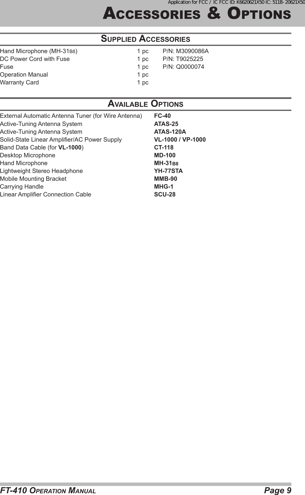
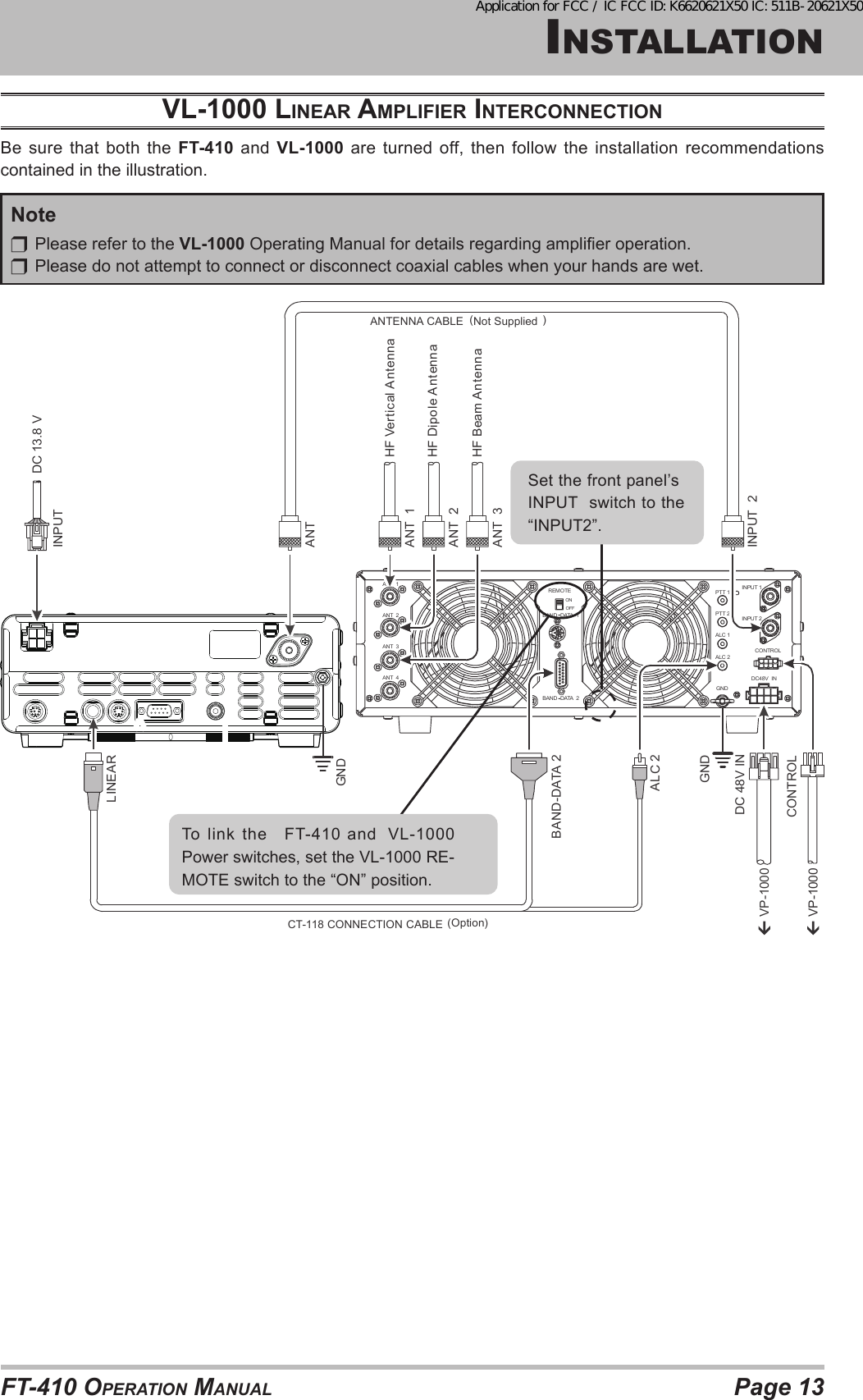
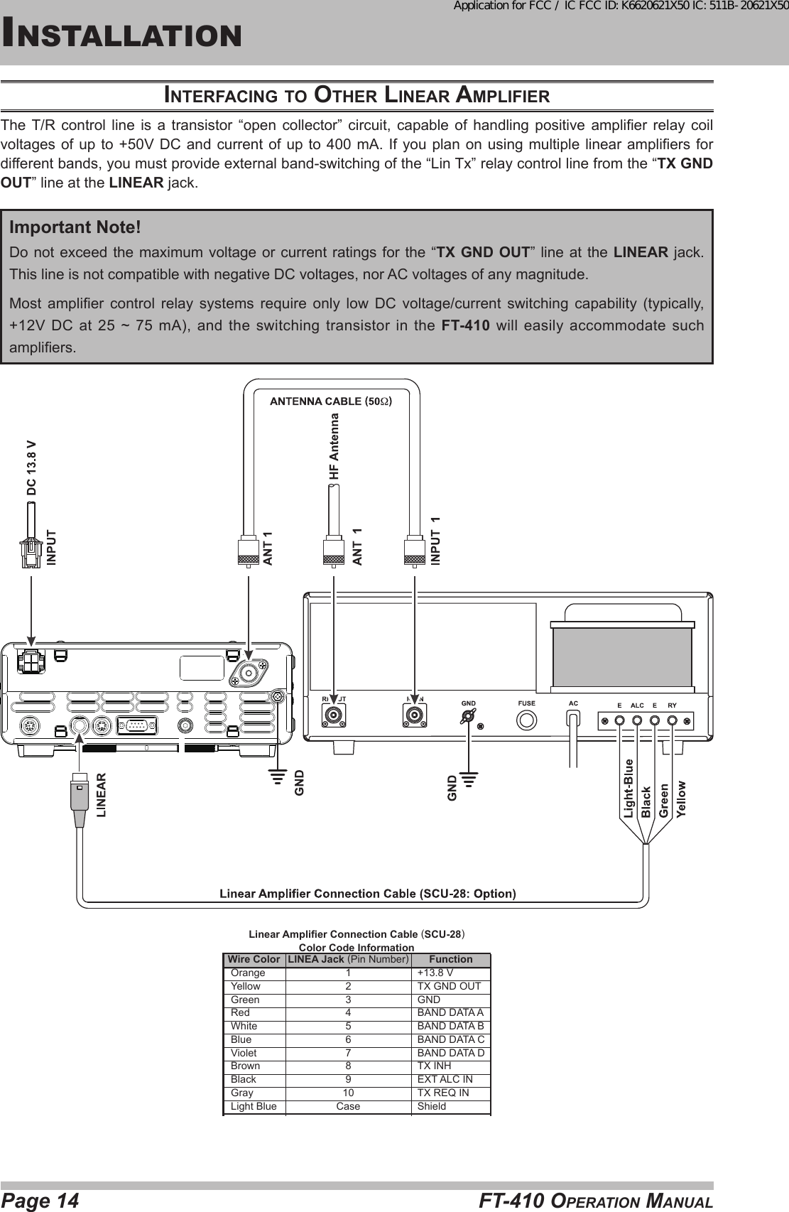
![Page 2 FT-410 OperaTiOn ManualTable OF cOnTenTsFront Panel Buttons and Knobs ........................ 3Display Indications ............................................. 6Rear Panel Jacks ................................................ 7Supplied MH-31B8 Microphone ......................... 8Accessories & Options ...................................... 9Supplied Accessories ......................................................... 9Available Options ............................................................... 9Installation ......................................................... 10Connection of Antenna and Power Supply....................... 10About Coaxial Cable .........................................................11Grounding ........................................................................ 12Installation ......................................................... 12VL-1000 Linear Amplier Interconnection ........................ 13Interfacing to Other Linear Amplier ................................. 14Easy Operation ................................................. 15Receiving ................................................................... 15Transmit ..................................................................... 15Menu Operation ............................................................... 15Resetting the Microprocessor .......................................... 16Menu Mode Reset ..................................................... 16All Reset .................................................................... 16Receiving........................................................... 17Tuning Steps .................................................................... 17Change the Tuning Step of the [MAIN DIAL] Knob .... 17About the [UP]/[DWN] buttons of the MH-31B8 ............... 17Clarier ............................................................................. 18DIAL Lock ......................................................................... 18ATT (Adjust the Receiving Sensitivity) ............................. 18Noise Blanker (Interference Rejection) ............................ 18Convenience Features ..................................... 19 AGC (Tool for Comfortable and effective Reception) ...... 19SHIFT (Interference Rejection) ........................................ 19RF GAIN ........................................................................... 20SSB/AM Mode Transmission ........................... 21TX Power Adjustment ....................................................... 21CW Mode Operation ......................................... 22Setup for Straight Key (and Straight Key emulation) Operation ....... 22Using the Built-in Electronic Keyer ................................... 23Adjusting the Keyer Speed ........................................ 23Memory Operation ............................................ 24Convenient Memory functions .......................................... 24Quick Point: ............................................................... 24Regular Memory Operation .............................................. 24Memory Storage ........................................................ 24Memory Channel Recall ............................................ 24Regular Memory Operation .............................................. 25Erasing Memory Channel Data .................................. 25Memory Tune Operation ............................................ 25Scanning Operation ......................................... 26VFO and Memory Scanning ............................................. 26Preparation ................................................................ 26VFO/Memory Scan .................................................... 26Operation on Alaska Emergency Frequency: 5167.5 kHz (U.S. Version Only) ........................ 27Preparation ............................................................................. 27Operation ................................................................... 27Specications ................................................... 28FCC Notice ........................................................ 30Application for FCC / IC FCC ID: K6620621X50 IC: 511B-20621X50](https://usermanual.wiki/Yaesu-Musen/20621X50.Users-Manual-Part-1/User-Guide-2622982-Page-2.png)
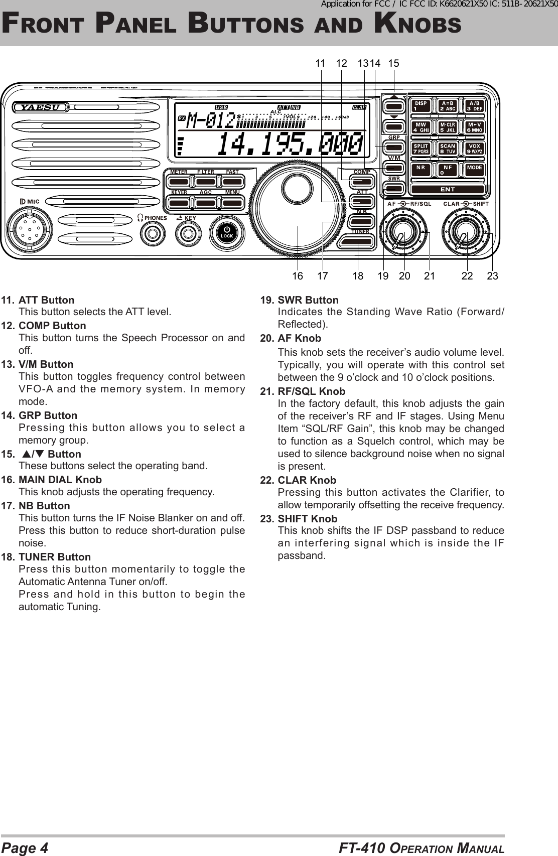
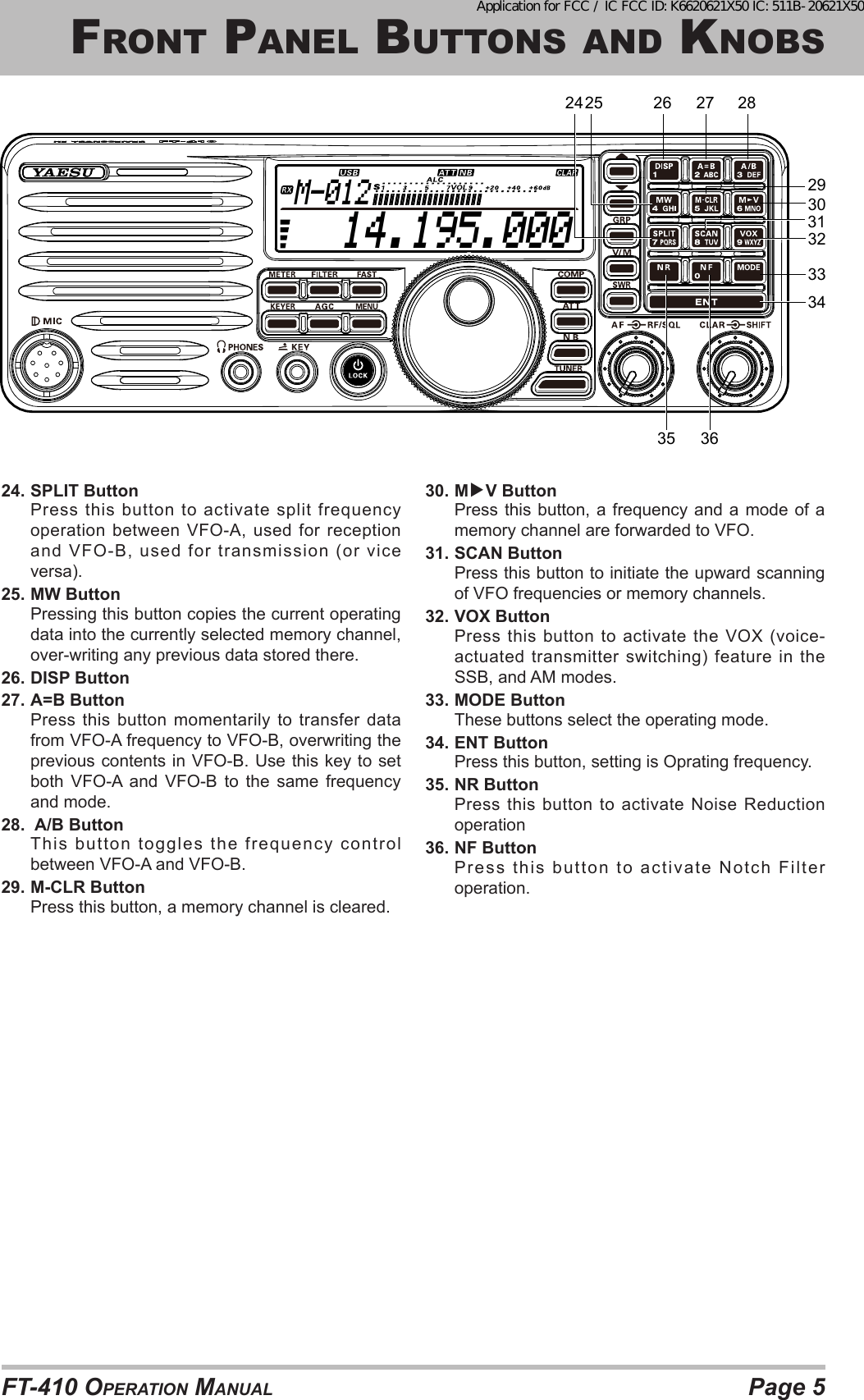
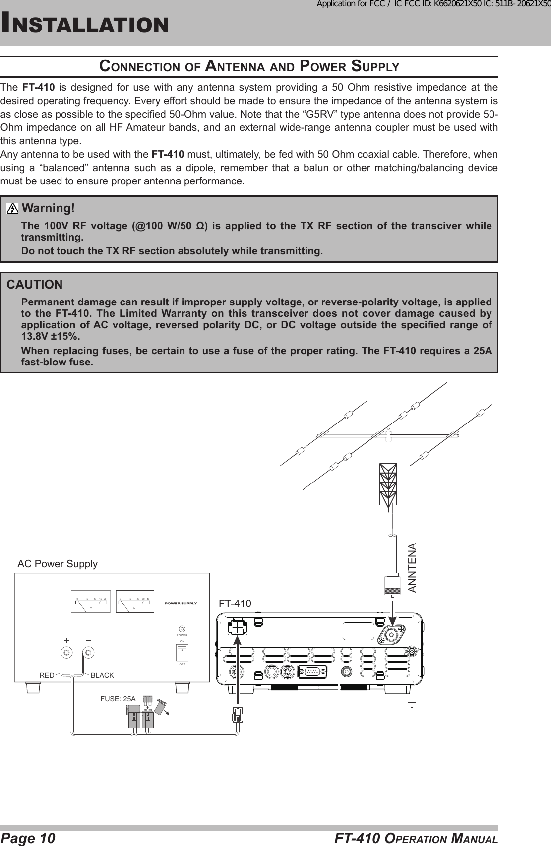
![Page 3FT-410 OperaTiOn ManualFrOnT panel buTTOns and KnObs 14.195.000M-0121 2 34 6 7 8 9 1051. METER ButtonPress this button to change the meter function in the transmit mode as follows.PO ALC SWR POPO: Indicates the average power output level.ALC: Indicates the relative ALC voltage.SWR: Indicates the Standing Wave Ratio (Forward/Reected).2. Filter ButtonPress this button to change the lter.3. FAST ButtonPressing this button will increase or decrease the tuning rate of the [MAIN DIAL] knob.4. MIC JackThis 8-pin jack accepts input from a supplied Hand Microphone.5. PHONE JackA 3.5 mm, 3-contact jack accepts either monaural or stereo headphones with 2 or 3-contact plugs. When a plug is inserted, the loudspeaker is disabled.Note:When wearing headphones, we recommend that you turn the AF GAIN levels down to their lowest settings before turning power on, to minimize the impact on your hearing caused by audio “pops” during switch-on.6. KEYER ButtonThis button toggles the internal CW keyer on and off.7. KEY JackThis 3.5 mm, 3-contact jack accepts a CW key or keyer paddles (for the built-in electronic keyer), or output from an external electronic keyer. Pinout is shown below. Key up is 5 volts, and key down current is 0.5 mA.Do not use the plug except the 3.5-mm 3-pin type plug. If the plug in correct size is not used the radio may be harmed or damaged.If the Keyer plug is removed from the jack while the FT-410 is in operation, the FT-410 may be switched to the transmit mode.Turn off the power of the FT-410 before connecting or disconnecting the Keyer.8. AGC ButtonThis button selects the AGC characteristics for the receiver.9. Power / LOCK ButtonPress and hold in this button for one second to turn the transceiver on or off. Press this button the locking of the [MAIN DIAL] knob and some switches, to prevent accidental frequency changes.10. MENU ButtonPress this button, the Menu Item and a title for the Menu Mode will appear in the display.Application for FCC / IC FCC ID: K6620621X50 IC: 511B-20621X50](https://usermanual.wiki/Yaesu-Musen/20621X50.Users-Manual-Part-1/User-Guide-2622982-Page-3.png)
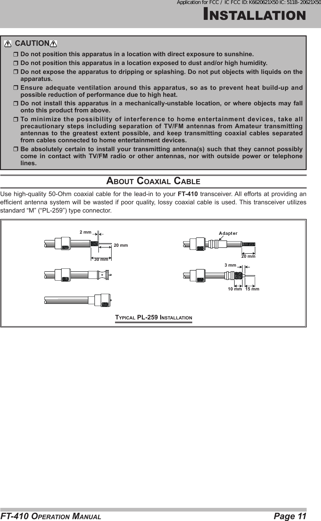
![Page 6 FT-410 OperaTiOn Manualdisplay indicaTiOns 14.195.000M-012Display 14.195.000M-0122345611. Information Display: Indicates the RF attenuator status (“ON” or “OFF”) selected for operation by the [ATT] button.: Indicates the Noise Blanker status (“ON” or “OFF”).////: Displays the currently selected operating mode.: This indicator appears whenever the VOX (automatic voice-actuated transmitter switching) circuit is activated.: This indicator appears whenever the Clarier function is activated.2. TX / RX DisplayTX: This indicator appears during transmission.RX: This indicator appears whenever the receiver squelch is open.3. Indicates the operating band name, and memory channelWhen in VFO mode, the operating band name (A or B) is displayed.While in memory mode, and the memory channel number are displayed.4. AF level indication5. MeterWhile receiving, the received signal strength is displayed.While transmitting, the meter displays PO, ALC, or SWR (determined by the [METER/DIM] button).6. Frequency DisplayThe operating frequency is displayed.Application for FCC / IC FCC ID: K6620621X50 IC: 511B-20621X50](https://usermanual.wiki/Yaesu-Musen/20621X50.Users-Manual-Part-1/User-Guide-2622982-Page-6.png)
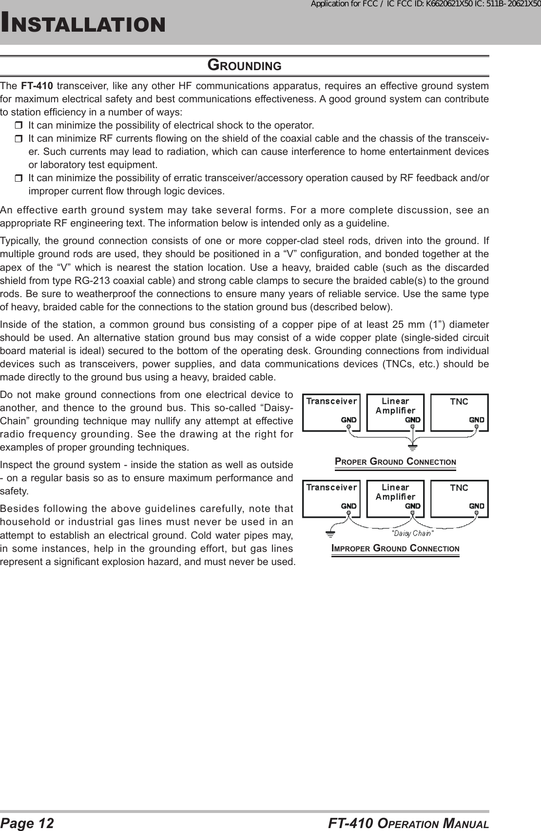
![Page 7FT-410 OperaTiOn Manualrear panel JacKs1 28765431. DC IN JackThis is the DC power supply connection for the transceiver. Use the supplied DC cable to connect directly to the car battery or to a DC power supply, which must be capable of supplying at least 22 A @13.8 VDC.(viewed from rear panel)+-2. ANT JackConnect your antenna here, using a type-M (PL-259) coaxial connector and 50 Ohm coaxial feedline.Warning!: High Power RF voltage is present at the TX RF section of the transceiver while transmitting. Absolutely! Do not touch the TX RF section while transmitting.3. GND TerminalFor safety and optimum performance, use this terminal to connect the transceiver to a good earth ground. Use a large diameter, short braided cable for making ground connections. Refer to page 12 for other notes about proper grounding.4. TUNER JackThis 8-pin jack is used for Connection to the FC-40 External Automatic Antenna Tuner. TXD TX GND OUT +13.8V OUT GND TUNER SENSE TX INH IN RXD RESET OUT (viewed from rear panel)5. LINEAR JackThis 10-pin output jack provides band selection data, which may be used for control of the optional VL-1000 Solid-State Linear Amplier.BAND DATA-A (LSB)TX GND OUT+13.8V OUTTXREQ INGNDBAND DATA-B BAND DATA-CBAND DATA-D (MSB)TX INH INEXT ALC IN (viewed from rear panel)6. DATA JackThis 6-pin input/output jack provides receiver audio and squelch signals, and accepts transmit (AFSK) audio and PTT control, from an external packet TNC.SQL OUT FSK IN GND DATA IN DATA PTTDATA OUT(viewed from rear panel)7. CAT JackThis 9-pin serial DB-9 jack allows external computer control of the FT-410. Connect a (straight) serial cable here and to the RS-232C COM port on your personal computer (no external interface is required).CTS RTSGNDSERIAL INSERIAL OUTConnect to , Connect to ,N/A Connect to ,(viewed from rear panel)8. EXT SPKR JackThis 3.5-mm, 2-pin jack provides variable audio output for an external speaker. The audio output impedance at this jack is 4 - 16 Ohms and the level varies according to the setting of the front panel’s [AF] knob. Inserting a plug into this jack disables the internal loudspeaker.Application for FCC / IC FCC ID: K6620621X50 IC: 511B-20621X50](https://usermanual.wiki/Yaesu-Musen/20621X50.Users-Manual-Part-1/User-Guide-2622982-Page-7.png)
![Page 15FT-410 OperaTiOn Manualeasy OperaTiOn 14.195.000M-012[Power / LOCK] button[MAIN DIAL] knob[MODE] button[AF] knob[RF/SQL] knob[▼]/[▲] buttonreceiviNG1. Connect your antenna to the ANT jack on the rear panel.2. Connect the after-market DC power supply (or car battery) using the supplied DC power cable, and set the POWER switch of the DC power supply to on.3. Press and hold in the [Power / LOCK] switch for one second to turn the transceiver on.4. Rotate the [RF/SQL] knob to the fully clockwise position.5. Rotate the [AF] knob to set a comfortable audio level on incoming signals or noise. Clockwise rotation of the [AF] knob increases the volume level.6. Press the []/[] button to select the amateur band which you wish to begin operating.7. Press the [MODE] button to select the desired operating mode.8. Rotate the [MAIN DIAL] knob to set the desired frequency.trANSmit1. Connect the Microphone to the MIC jack on the front panel.2. To transmit, press the microphone’s PTT (Push To Talk) switch, speak into the microphone in a normal voice level.3. Release the PTT switch to return to the receive mode.meNu operAtioNThe Menu System allows you to customize a wide variety of transceiver performance aspects and operating characteristics. After you have initially customized the various Menu procedures, you will nd that you will not have to resort to them frequently during everyday operation.1. Press the [MENU] button to enter the Menu Mode. The “Menu.” will appear on the display.2. Rotate the [MAIN DIAL] knob to select the Menu Item to be adjusted.3. Press the [GRP] button to enable adjustment of the selected Menu Item. The “>>” will appear on the display.4. Rotate the [MAIN DIAL] knob to adjust or select the parameter to be changed.5. Press the [GRP] button to save the selection. The icon appears continuously.6. Press the [MENU] button to return to normal operation. 14.195.000M-012[MENU] button[MAIN DIAL] knob[GRP] buttonApplication for FCC / IC FCC ID: K6620621X50 IC: 511B-20621X50](https://usermanual.wiki/Yaesu-Musen/20621X50.Users-Manual-Part-1/User-Guide-2622982-Page-15.png)