Yaesu Musen 20605X20 Analog Scanning Receiver User Manual part 3
Yaesu Musen Co., Ltd. Analog Scanning Receiver part 3
UserManual.wiki
>
Yaesu Musen
>
20605X20 User Manual
>
User Manual - part 3
Contents
1.
User Manual - part 1
2.
User Manual - part 2
3.
User Manual - part 3
4.
User Manual - part 4
User Manual - part 3
Navigation menu
Upload a User Manual
Namespaces
Wiki Guide
HTML
PDF
Info
Views
User Manual
Discussion / Help
Navigation
![26PreparationUsing a microSD Memory CardFormatting a microSD Memory CardFormat a new microSD memory card following the steps below before use�CautionFormatting a microSD memory card erases all data saved on it� If you are going to format the microSD memory card you are using, be sure to check the data saved on it before formatting�1 Press and hold for over 1 second� The “SETUP MENU” screen appears�2 Touch [SD CARD]�3 Touch [FORMAT]� [OK?] appears on the LCD�4 Touch [OK]� Tip To cancel formatting, select [Cancel]� on the LCD blinks and formatting starts� When formatting is completed, a beep sounds and [Completed] appears on the LCD� T�B�D�T�B�D�Application for FCC / IC FCC ID: K6620605X20 IC: 511B-20605X20](https://usermanual.wiki/Yaesu-Musen/20605X20.User-Manual-part-3/User-Guide-2549781-Page-6.png)
![28Basic OperationPerforming Communication2 Input the call sign toggling the alphabet input screen and number input screen� Supplement The alphabet input screen can be switched to the number input screen by touching [数字記号]� The number input screen can be switched to the alphabet input screen by touching [ABC]�3 Press � The call sign is set and the frequencies of both A-band and B-band is displayed simultaneously� (see page xx) Supplement Factory settings are: A-band (upper): 145�000 MHz B-band (lower): 433�000 MHz Tip You can change the information such as the power supply voltage and the opening message displayed at power-on� For example, press and hold for over 1 second to enter Set mode and then select [DISPLAY] → [9 OPENING MESSAGE] to change the setting� In addition, you can also set the transceiver to display the reception frequency immediately without displaying the opening message ( see page xx)� yTurning off the TransceiverTo turn off the transceiver, press and hold for over 1 second�メモリー書き込み中!A1Application for FCC / IC FCC ID: K6620605X20 IC: 511B-20605X20](https://usermanual.wiki/Yaesu-Musen/20605X20.User-Manual-part-3/User-Guide-2549781-Page-8.png)
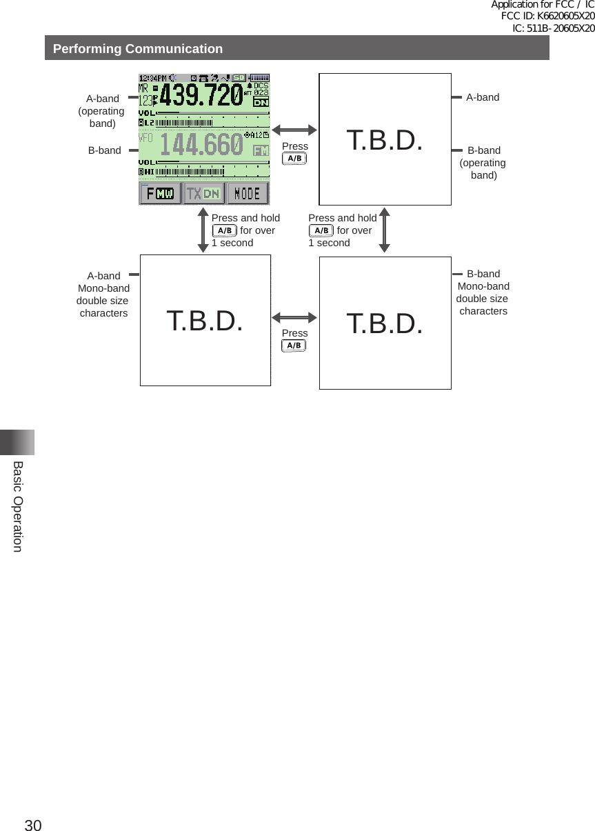
![29Basic OperationPerforming CommunicationAdjusting the Volume LevelYou can adjust the transceiver volume level for the A-band and B-band separately�1 Press to select the band for which you want to adjust the volume level� Pressing each time toggles between the A-band and B-band�2 Rotate the VOL knob clockwise/counterclockwise to adjust the volume level� The [VOL] gauge moves right/left� Supplement If no sound is heard from the speaker, press and then adjust the volume level while listening to white noise�Toggling the Operating BandNormally, 2 operating bands are displayed on the top half and bottom half of the transceiver touch screen� This is called Dual band�With one of the bands selected, change the frequency and radio wave form� The selected band is called Operating band� The other band is called Sub-band�Each time pressing toggles the operating band� Pressing and holding for over 1 second displays only the operating band which is called Mono-band�On how to toggle operating bands, see the following illustrations�Application for FCC / IC FCC ID: K6620605X20 IC: 511B-20605X20](https://usermanual.wiki/Yaesu-Musen/20605X20.User-Manual-part-3/User-Guide-2549781-Page-9.png)