Yaesu Musen 20605X20 Analog Scanning Receiver User Manual part 2
Yaesu Musen Co., Ltd. Analog Scanning Receiver part 2
UserManual.wiki
>
Yaesu Musen
>
20605X20 User Manual
>
User Manual - part 2
Contents
1.
User Manual - part 1
2.
User Manual - part 2
3.
User Manual - part 3
4.
User Manual - part 4
User Manual - part 2
Navigation menu
Upload a User Manual
Namespaces
Wiki Guide
HTML
PDF
Info
Views
User Manual
Discussion / Help
Navigation
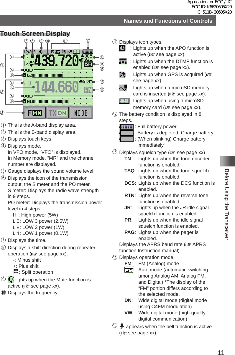
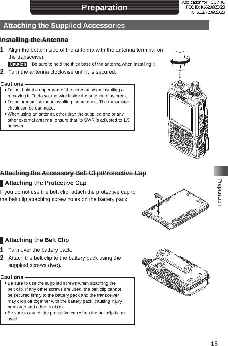
![12Before Using the TransceiverNames and Functions of Controls yDual Band ScreenA-band and B-band are displayed in a top-down fashion�メモリー書き込み中!A1• Touching [F MW] displays the function menu screen�• Touching [TX DN] enables for the communication mode to be fixed on the transmission side�• Touching [MODE] switches between Analog and Digital� yBand Scope ScreenWhen the band scope operation is enabled, the display is as follows� Reference You can change the number of band scope channels by selecting [DISPLAY] → [4 BAND SCOPE] in Set mode� You can select 17 channels, 35 channels or 71 channels� yFunction Menu ScreenTouching [F MW] displays the function menu screen�MENU DISPLAY 2'!A7723 TOP画面プリセットレシーバー!A1TOP画面AF-DUAL表示'!A1 Band Scope'!A1FUNCTION!A389 APRS Message list1'!A1APRS Station list1'!A1Application for FCC / IC FCC ID: K6620605X20 IC: 511B-20605X20](https://usermanual.wiki/Yaesu-Musen/20605X20.User-Manual-part-2/User-Guide-2549780-Page-2.png)
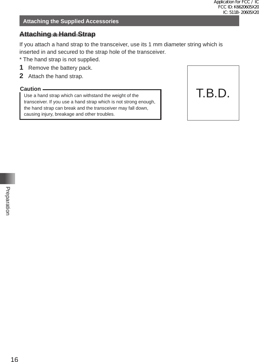
![13Before Using the TransceiverNames and Functions of Controls yBACKTRACK ScreenPressing the key displays the BACKTRACK screen�• The compass setting is displayed to the upper left of the compass icon� “H-UP” is displayed when the direction in which you are heading is set to always facing up, whereas “N-UP” is displayed when North is set to always facing up� In the Set mode option [DISPLAY] → [3 COMPASS], you can change the compass setting�• Upon retrieval of the registered position information, the distance from the current position displays to the upper right of the compass icon�• Touching [YR] displays the position of the received friend station displays on the compass icon (only when the signal carries the position information)�• Touching [MY] displays your heading direction on the compass icon�• Touching [MEMORY] switches to the mode for registering the current position information�• Touching [★] displays the position information registered with the “★” tag� When touching while flashing, the position information displayed on the compass icon is stored in the memory with a “★” tag�• Touching [L1] displays the position information registered with the “L1” tag� When touching while flashing, the position information displayed on the compass icon is stored in the memory with an “L1” tag�• Touching [L2] displays the position information registered with the “L2” tag� When touching while flashing, the position information displayed on the compass icon is stored in the memory with an “L2” tag�Application for FCC / IC FCC ID: K6620605X20 IC: 511B-20605X20](https://usermanual.wiki/Yaesu-Musen/20605X20.User-Manual-part-2/User-Guide-2549780-Page-3.png)
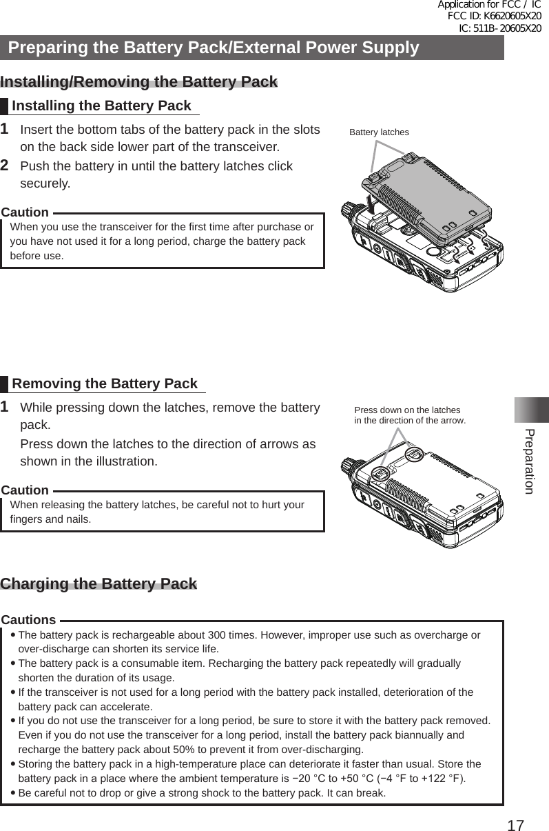
![14Before Using the TransceiverNames and Functions of ControlsEntering LettersThe keyboard screen appears for inputting letters such as your call sign or a memory channel tag� yNumber & Symbol Input Screen• Touch [ABC] to display the alphabet input screen�• Touching [123] switches the key to [#&%] and displays the symbol input screen� Touching each time switches between the number input screen and the symbol input screen�• Touch [] [ ] to move the cursor to left/right in the text input area� yAlphabet Input Screen• Touching [ABC] each time switches between upper case letters and lower case letters�Application for FCC / IC FCC ID: K6620605X20 IC: 511B-20605X20](https://usermanual.wiki/Yaesu-Musen/20605X20.User-Manual-part-2/User-Guide-2549780-Page-4.png)