Yaesu Musen 20523X50 VHF DIGITAL/ANALOGUE TRANSCEIVER User Manual OM
Yaesu Musen Co., Ltd. VHF DIGITAL/ANALOGUE TRANSCEIVER OM
UserManual.wiki
>
Yaesu Musen
>
20523X50 User Manual
>
User Manual 2
Contents
1.
User Manual - 1
2.
User Manual 2
3.
User Manual - 2
User Manual 2
User Manual - 2
Navigation menu
Upload a User Manual
Namespaces
Wiki Guide
HTML
PDF
Info
Views
User Manual
Discussion / Help
Navigation
![21Advanced OperationFTM-3200DR Operating ManualCTCSS OperationThis radio is equipped with the CTCSS (Continuous Tone-coded Squelch System which allows audio to be heard only when receiving signals containing the same frequency tone as the tone that has been set in the tone squelch menu. By matching the tone frequency with the partner station in advance, a quiet standby monitoring is possible.Caution: CTCSS does not function in digital mode. To transmit a signal using a CTCSS code, use the [D/A(GM)] key to switch the communication mode to AMS (Auto Mode Select function) or analog (FM) mode.1. Press and hold in the [MHz(SETUP)] key for over 1 second. The Setup menu appears.2. Rotate the DIAL knob to select “SQL TYPE 42”, then press the [MHz(SETUP)] key.3. Rotate the DIAL knob to select “TSQL”, then press and hold in the [MHz(SETUP)] key for over 1 second. Displays “ ” on the screen. The squelch opens only when receiving tone signals of the set frequency.Note: From the Setup Menu, you can change the CTCSS setting.TONE FRQ 45 à The tone frequency can be selected from 50 frequencies.BELL 6 à A bell tone (beep) may be set to sound when signals containing a corresponding CTCSS tone are received.Tone SearchIn operating situations where you don’t know the CTCSS tone being used by another station or stations, you can command the radio to listen to the incoming signal and scan in search of the tone being used.Note: For details, refer to the Advanced Manual (download from the Yaesu website).DCS OperationThis radio is equipped with a DCS (Digital Coded Squelch) function that allows audio to be heard only when signals containing the corresponding DCS code are received. By matching the DCS code with the partner stations beforehand, a quiet receive standby is possible.Caution: DCS does not function in digital mode. To transmit a signal with a DCS code, use the [D/A(GM)] key to switch the communication mode to AMS (Auto Mode Select function) or analog (FM) mode.1. Press and hold in the [MHz(SETUP)] key for over 1 second. The Setup menu appears.2. Rotate the DIAL knob to select “SQL TYPE 42”, then press the [MHz(SETUP)] key.Application for FCC / IC FCC ID: K6620523X50 / IC: 511B-20523X50](https://usermanual.wiki/Yaesu-Musen/20523X50.User-Manual-2/User-Guide-2879978-Page-1.png)
![22Advanced OperationFTM-3200DR Operating Manual3. Rotate the DIAL knob to select “DCS”, then press and hold in the [MHz(SETUP)] key for over 1 second. Displays “ ” on the screen. The squelch opens only when receiving a signal con-taining the corresponding DCS code.Note: From the Setup Menu, you can change the DCS setting.DCS CODE 9 à The DCS code can be selected from 104 codes.BELL 6 à A bell tone (beep) may be set to sound when signals containing a corresponding DCS code are received.DCS SearchIn operating situations where you don’t know the DCS code being used by another station or stations, you can command the radio to listen to the incoming signal and scan in search of the code being used.Note: For details, refer to the Advanced Manual (download from the Yaesu website).EPCS (Enhanced Paging & Code Squelch) OperationUse the pager code consisting of 2 CTCSS tones to exchange communications with specified stations.Note: For details, refer to the Advanced Manual (download from the Yaesu website).Split Tone OperationThe FTM-3200R can be operated in a “Split Tone” configuration, to enable operation on repeaters using a mix of both CTCSS and DCS control via the Setup menu.Note: For details, refer to the Advanced Manual (download from the Yaesu website).DTMF OperationDTMF tones (Dual Tone Multi Frequencies) are the tones you hear when dialing from a telephone keypad. The FTM-3200DR transceiver can transmit the DTMF codes by using the keys on the microphone or recalling registered numbers from memories.The maximum of 16-digit DTMF codes can be registered in up to 10 memory channels.It is convenient to register telephone patch numbers, and network linking sequences to the DTMF memory channels.Note: For details, refer to the Advanced Manual (download from the Yaesu website).Application for FCC / IC FCC ID: K6620523X50 / IC: 511B-20523X50](https://usermanual.wiki/Yaesu-Musen/20523X50.User-Manual-2/User-Guide-2879978-Page-2.png)
![23FTM-3200DR Operating ManualMemory OperationThe FTM-3200R provides a wide variety of memory system resources. These include:r 199 “basic” memory channels, numbered “1” through “199”.r A “Home” channel, providing storage and quick recall of one prime frequency.r 10 sets of band-edge memories, also known as “Programmable Memory Scan” channels, labeled “L0/U0” through “L9/U9”.Each memory may be appended with an alpha-numeric label of up to 8 characters, for quick channel recognition.Memory Storage1. In the VFO mode, select the desired frequency, repeater shift, CTCSS/DCS tone, and TX power level.2. Press and hold in the [V/M(MW)] key for 1 second. A memory number will appear in the bottom right corner of the display.Note: If the channel number is blinking, there currently is no data stored on that channel; if the channel number is not blinking, that channel is currently “occupied” by other frequency data.VOLDIALSQLTXPO DW MWSETUPREV D/A V/MMHz3. Within five seconds of pressing the [V/M(MW)] key, use the DIAL knob to select the desired memory into which you wish to store the frequency.4. Press the [V/M(MW)] key again, this time momentarily, to store the displayed data into the selected memory channel slot.5. To store other frequencies, repeat steps 1 through 4, remembering to set the repeater shift, CTCSS/DCS tone, and TX power level, as appropriate.Split MemoryA separate transmit frequency may be registered to a memory channel to which a receive frequency has already been registered.Note: For details, refer to the Advanced Manual (download from the Yaesu website).Naming a Memory ChannelYou may wish to append an alpha-numeric “Tag” (label) to a memory or memories, to aid in recollection of the channel’s use (such as club name, etc.).Note: For details, refer to the Advanced Manual (download from the Yaesu website).Memory Only ModeOnce memory channel programming has been completed, you may place the radio in a “Memory Only” mode, whereby VFO operation is impossible.Note: For details, refer to the Advanced Manual (download from the Yaesu website).Application for FCC / IC FCC ID: K6620523X50 / IC: 511B-20523X50](https://usermanual.wiki/Yaesu-Musen/20523X50.User-Manual-2/User-Guide-2879978-Page-3.png)
![24Memory OperationFTM-3200DR Operating ManualMemory RecallOnce you have stored the memory or memories desired, you must now switch from the “VFO” mode to the “Memory Recall” mode, so you can operate on the just-stored memory channels.1. Press the [V/M(MW)] key, repeatedly if nec-essary, until the “ ” icon and a memory channel number appear on the display; this indicates that the “Memory Recall” mode is now engaged.2. When more than one memory has been stored, use the DIAL knob to select any of the programmed memories for operation.VOLDIALSQLTXPO DW MWSETUPREV D/A V/MMHzNote: Alternatively, the microphone’s [UP] or [DWN] button may be used to step or scan through the available memories. When using the microphone’s buttons, press the button momentarily to move one step up or down; press and hold in the [UP] or [DWN] button for one second to begin memory scanning.Memory Recall from the Microphone’s KeypadWhile operating in the Memory Recall mode, the keypad of the MH-48A6J Microphone may be used for direct recall of memory channels.To do this, press the Channel Number you wish to recall, then press the [#] key.For example:To recall Memory Channel “5”, press [5] à [#]To recall Memory Channel “123”, press [1] à [2] à [3] à [#]You may also recall Programmable Memory Scan (PMS) channels (“L0/U0” through “L9/U9”) using the following numbers:L1 201 L6 211U1 202 U6 212L2 203 L7 213U2 204 U7 214L3 205 L8 215U3 206 U8 216L4 207 L9 217U4 208 U9 218L5 209 L0 219U5 210 U0 220Moving Memory Data to the VFOData stored on memory channels can easily be moved to the VFO.Note: For details, refer to the Advanced Manual (download from the Yaesu website).Application for FCC / IC FCC ID: K6620523X50 / IC: 511B-20523X50](https://usermanual.wiki/Yaesu-Musen/20523X50.User-Manual-2/User-Guide-2879978-Page-4.png)
![25Memory OperationFTM-3200DR Operating ManualMasking MemoriesThere may be situations where you want to “Mask” memories so they are not visible during memory selection or scanning. (except for Memory Channel “1”, the Priority Channel, and the Home Channel).1. In the Memory Recall mode, press and hold in the [V/M(MW)] key for 1 second, then rotate the DIAL knob to select the memory channel you wish to mask.3. Press the [SQL(TXPO)] key. The erase confirmation screen appears.4. Press the [SQL(TXPO)] key. The previously selected memory will be “masked”.VOLDIALSQLTXPO DW MWSETUPREV D/A V/MMHzNote: Press the [V/M(MW)] key to cancel the memory mask.Un Masking Memory1. To Unmask a hidden memory, in the Memory Recall mode, press and hold in the [V/M(MW)] key for 1 second.2. Rotate the DIAL knob to select the masked memory’s number.3. Press the [SQL(TXPO)] key to restore the memory channel’s data.HOME Channel MemoryA convenient one-touch “Home” channel memory is available to simplify return to your most often used frequency.To recall the Home channel, just press the [V/M(MW)] key, repeatedly if necessary, until the “ ” icon appears on the display; this indicates that the Home Channel has been recalled.Note: When shipped from factory, the Home Channel set to 146.520 MHz (USA version) or 144.000 MHz (EXP version).VOLDIALSQLTXPO DW MWSETUPREV D/A V/MMHzChanging the frequency of the home channelThe default frequency setting of the home channel can be changed.1. In the VFO mode, tune to the desired Home channel frequency.2. Press and hold in the [V/M(MW)] key for 1 second, then press the [REV(DW)] key. The overwrite confirmation screen appears.4. Press the [REV(DW)] key. The home channel frequency is overwritten.Application for FCC / IC FCC ID: K6620523X50 / IC: 511B-20523X50](https://usermanual.wiki/Yaesu-Musen/20523X50.User-Manual-2/User-Guide-2879978-Page-5.png)
![26 FTM-3200DR Operating ManualScanningBasic Scanner OperationBefore activating the scanner, make sure that the Squelch is set to silence the back ground noise when no signal is present. Scanning is not possible while the Squelch is open (if noise or signals are being heard).Scanning may be started or stopped using the micro-phone’s [UP] or [DWN] button.The following techniques are used for scanning:r Pressing and holding in either the [UP] or [DWN] button for one second in the VFO mode will cause upward or downward band scanning, respectively, to begin.r Pressing and holding in either the [UP] or [DWN] button for one second in the Memory mode will cause memory channel scanning toward a higher- or lower-numbered memory channel, respectively.LOCKP3P2P171482059BACD36P4LAMPDTMF MICROPHONEMH-48ABCJKLTUVGHIPQRSDEFMNOWXYZMICDWN UPr Scanning pauses when a signal opens the squelch, and the decimal point on the display will blink. You can choose one of three scan-resume modes (described later).r To halt the scan manually, the easiest way is to push the PTT switch on the microphone momentarily (no transmission will occur while you are scanning). The scan may also be halted manually by pressing the microphone’s [UP] or [DWN] button, or the [V/M(MW)] key.Scan Resume OptionsSelect one of the 3 scan resume modes to be performed after the scanning stops.Note: For details, refer to the Advanced Manual (download from the Yaesu website).Memory Skip ScanningMemory channels which you do not want to receive can be skipped during scanning.Note: For details, refer to the Advanced Manual (download from the Yaesu website).Preferential Memory ScanSet up a “Preferential Scan List” of channels which you can “flag” within the memory system.Note: For details, refer to the Advanced Manual (download from the Yaesu website).Programmable Memory Scan (PMS)Using the dedicated PMS memory channels, only the frequencies within the specified frequency range will be scanned.Note: For details, refer to the Advanced Manual (download from the Yaesu website).Priority Channel Scanning (Dual Watch)Scanning features include a two-channel scanning capability which allows you to operate on a VFO, Memory channel, or Home channel, while periodically checking a user defined Memory Channel for activity.Note: For details, refer to the Advanced Manual (download from the Yaesu website).Application for FCC / IC FCC ID: K6620523X50 / IC: 511B-20523X50](https://usermanual.wiki/Yaesu-Musen/20523X50.User-Manual-2/User-Guide-2879978-Page-6.png)
![27FTM-3200DR Operating ManualGM FunctionWhat is the GM (Group Monitor) Function?The GM function automatically monitors for any other stations with the GM function in operation on the same frequency, or stations transmitting in DN mode, within communica-tion range. In addition to notifying you of the group members within your communication range, the GM function also displays the detected call sign on the transceiver screen.Caution: The GM function does not work while in the analog (FM) mode.àDisplaying all the stations using the GM function1. Tune to the designated frequency.2. Press and hold in the [D/A(GM)] key for 1 second. The GM function activates and displays up to 24 stations using the GM mode on the same frequency, or stations operating in DN mode, within the communication range.Note: Displays “ ”for stations within your communication range. Displays “ ” (blinks) for stations out-side your communication range.VOLDIALSQLTXPO DW MWSETUPREV D/A V/MMHz3. Press and hold in the [D/A(GM)] key for 1 second to disable the GM function and return to the frequency screen.Application for FCC / IC FCC ID: K6620523X50 / IC: 511B-20523X50](https://usermanual.wiki/Yaesu-Musen/20523X50.User-Manual-2/User-Guide-2879978-Page-7.png)
![28 FTM-3200DR Operating ManualMiscellaneous SettingsReset ProcedureIn some instances of erratic or unpredictable operation, the cause may be corruption of data in the microprocessor (due to static electricity, etc.). If this happens, resetting of the micro processor may restore normal operation. Note that all memories will be erased if you do a complete microprocessor reset, as described below.Microprocessor ResettingTo clear all memories and other settings to factory defaults:1. Turn the radio off.2. Press and hold in the [D/A(GM)], [MHz(SETUP)], and [V/M(MW)] keys while turning the radio on. The “ALL RESET PUSH V/M KEY” notation will scroll on the display.3. Press the [D/MR(MW)] key momentarily to reset all settings to their factory defaults(-press any other key to cancel the Reset procedure).Set Mode ResettingTo reset the Set (Menu) mode settings to their factory defaults, while leaving other settings unchanged:1. Turn the radio off.2. Press and hold in the [D/A(GM)] and [MHz(SETUP)] keys while turning the radio on. The “SET MODE RESET PUSH V/M KEY” notation will scroll on the display.3. Press the [D/MR(MW)] key momentarily to reset the Set (Menu) mode settings to their factory defaults (press any other key to cancel the Reset procedure).Programming the Key AssignmentsDefault FTM-3200DR key functions have been assigned to the Microphone’s [P1]/[P2]/[P3]/[P4] keys at the factory. These may be changed by the user, if you wish to assign quick access to another function.Note: For details, refer to the Advanced Manual (download from the Yaesu website).Keyboard BeeperA key/button beeper provides useful audible feedback whenever a key/button is pressed. If you want to turn the beeper off (or back on again).Note: See Setup Menu Item “BEP KEY 3” on page xx.Application for FCC / IC FCC ID: K6620523X50 / IC: 511B-20523X50](https://usermanual.wiki/Yaesu-Musen/20523X50.User-Manual-2/User-Guide-2879978-Page-8.png)
![31FTM-3200DR Operating ManualCloningThe FTM-3200R includes a convenient “Clone” feature, which allows the memory and configuration data from one transceiver to be transferred to another FTM-3200R.This can be particularly useful when configuring a number of transceivers for a public service operation.Here is the procedure for Cloning one radio’s data to another:1. Turn both radios off.2. Connect the user-constructed cloning cable between the MIC jacks of the two radios.3. Press and hold in the [LOW(A/N)] key while turning the radios on. Do this for both ra-dios (the order of switch-on does not matter). “CLONE” will appear on the displays of both radios when the Clone mode is successfully activated in this step.4. On the Destination radio, press the [D/MR(MW)] key (“- -WAIT- -” will appear on the LCD).5. Press the [MHz(SET)] key on the Source radio; “- - - -TX- - - -” will appear on the Source radio, and the data from this radio will be transferred to the other radio.6. If there is a problem during the cloning process, “ERROR” will be displayed. Check your cable connections and battery voltage, and try again.7. If the data transfer is successful, “CLONE” will appear on both displays.8. Press any key to exit to normal operation.9. Turn both radios off and disconnect the cloning cable.Application for FCC / IC FCC ID: K6620523X50 / IC: 511B-20523X50](https://usermanual.wiki/Yaesu-Musen/20523X50.User-Manual-2/User-Guide-2879978-Page-11.png)
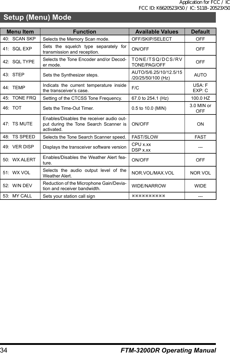
![32 FTM-3200DR Operating ManualSetup (Menu) ModeThe FTM-3200R Setup (Menu) mode, already described in parts of many previous chapters, is easy to activate and set. It may be used for configuration of a wide variety of transceiver parameters, some of which have not been detailed previously. Use the following procedure to activate the Setup (Menu) mode:1. Press and hold in the [MHz(SETUP)] key for 1 second to enter the Setup menu.2. Rotate the DIAL knob to select the Menu Item to be adjusted.3. Press the [MHz(SETUP)] key momentarily to enable adjustment of the selected Menu item, then rotate the DIAL knob to perform the actual adjustment.4. After completing your selection and adjust-ment, press and hold in the [MHz(SETUP)] key for 1 second to exit the Setup menu and resume normal operation.VOLDIALSQLTXPO DW MWSETUPREV D/A V/MMHzMenu Item Function Available Values Default 1: APO Enables/Disables the Automatic Power Off feature.0.5H to 12H (0.5H step)/OFF OFF 2: BCLO Enables/Disables the Busy Channel Lock-Out feature. ON/OFF OFF 3: BEP KEY Enables/Disables the key beeper. KEY+SCAN/KEY/OFF KEY+SCAN 4: BEP EDGE Enables/Disable the Band-edge beeper while scanning. ON/OFF OFF 5: BEP STBY Enables/Disable the Standby beep ON/OFF ON 6: BELL Selects the CTCSS/DCS/EPCS Bell Ringer repetitions. 1 to 20/CONTINUE/OFF OFF 7: CLK TYPE Shifting of the CPU clock frequency. A/B A 8: DC VOLT Indicates the DC Supply Voltage. --- --- 9: DCS CODE Setting of the DCS code. 104 standard DCS codes 02310: DCS INVSelect a combination of DCS inversion codes in terms of communication direc-tion.NORMAL/INVERT/BOTH NORMAL11: DIG AMS Sets the transmission mode TXMANUAL/TX FMFIX/TX DNFIX/AUTO TXMANUAL12: DI POPUP Sets the information pop-up time 2/4/6/8/10/20/30/60/CONTINUE/OFF 10 SEC13: DSQ CODE Sets the squelch code in digital mode. 001 to 126 CODE 00114: DSQ TYPE Sets the squelch type in digital mode. OFF/CODE/BREAK OFF15: DT AUTO Enables/Disables the DTMF Autodialer feature. MANUAL/AUTO MANUALApplication for FCC / IC FCC ID: K6620523X50 / IC: 511B-20523X50](https://usermanual.wiki/Yaesu-Musen/20523X50.User-Manual-2/User-Guide-2879978-Page-12.png)
![33Setup (Menu) ModeFTM-3200DR Operating ManualMenu Item Function Available Values Default16: DT DELAY Setting of the DTMF Autodialer’s TX De-lay Time. 50/250/450/750/1000 450 MS17: DT SET Loading of the DTMF Autodialer Memo-ries. --- ---18: DT SPEED Setting of the DTMF Autodialer Sending Speed. 50/100 50 MS19: DW RVRT Enables/Disables the “Priority Channel Revert” feature. ON/OFF OFF20: GM RINGREnables/Disables the alert sound when detecting stations within communication rangeIN RANGE/ALWAYS/OFF IN RANGE21: GM INTVL Selects the automatic sending interval. NORMAL/LONG NORMAL22: LCD DMMR Setting of the front panel display’s illumi-nation level. LEVEL 1/2/3/4 LEVEL 423: LOCK Selects the Control Locking Lockout combination.KEY+DIAL/PTT/KEY+PTT/DIAL+PTT/ALL/KEY/DIALKEY+DIAL24: MIC GAIN Adjust the microphone gain level. LEVEL 5 to 9 LEVEL 525: MEM NAME Programming an Alpha/Numeric label for a Memory Channel. --- ---26: MW MODE Selects the method of selection of chan-nels for Memory Storage. NEXT CH/LOWER CH NEXT CH27: OPEN MSG Selects the Opening Message that ap-pears when the radio is powered ON. OFF/DC/MESSAGE MESSAGE28: PAG CD-RSetting the Receiver Pager Code for the Enhanced CTCSS Paging & Code Squelch function.--- 05 4729: PAG CD-TSetting the Transmitting Pager Code for the Enhanced CTCSS Paging & Code Squelch function.--- 05 4730: PAG P1 Programming the function assigned to Microphone’s [P1] key.SQL OFFHOMEWX CHCD SRCHSCANT CALLTX POWERDIG/ANAGMSetup Menu Item #1 to 53SQL OFF31: PAG P2 Programming the function assigned to Microphone’s [P2] key. HOME32: PAG P3 Programming the function assigned to Microphone’s [P3] key. CD SRCH33: PAG P4 Programming the function assigned to Microphone’s [P4] key.Depends on the transceiv-er version.34: RADIO ID Displays the transceiver IDs øøø (uneditable) ---35: RF SQL Adjusts the RF Squelch threshold level. ON/OFF OFF36: RPT ARS Activates/Deactivates the Automatic Re-peater Shift feature. ON/OFF ON37: RPT FREQ Sets the magnitude of the Repeater Shift. 0.00 - 99.95 (MHz) 0.60 MHz38: RPT SFT Sets the Repeater Shift direction. -RPT/+RPT/SIMP SIMP39: SCAN RSM Selects the Scan Resume mode.BUSY/HOLD/2-10 (SEC) 5.0 SECApplication for FCC / IC FCC ID: K6620523X50 / IC: 511B-20523X50](https://usermanual.wiki/Yaesu-Musen/20523X50.User-Manual-2/User-Guide-2879978-Page-13.png)

![35FTM-3200DR Operating ManualSpecificationsGeneralFrequency Range: Tx 144 - 148 MHz Rx 136 - 174 MHzChannel Step: 5/6.25/10/12.5/15/20/25/50/100 kHzStandard Repeater Shift: ±600 kHzFrequency Stability: ±2.5 ppm [-4 °F to +140 °F (-20 °C to +60 °C)]Modes of Emission: F3E/F7WAntenna Impedance: 50 Ohms, unbalancedSupply voltage: 13.8 V DC ±15 %, negative groundCurrent Consumption (typical): Rx: less than 0.7 A, less than 0.5 A (squelched) Tx: 15 A (65 W) /10 A (30 W) /5 A (5 W)Operating Temperature Range: -4° F to +140° F (-20° C to +60° C)Case Size (WxHxD): 6.1” x 1.7” x 6.1” (154 x 43 x 155 mm) (w/o knobs)Weight (Approx.): 2.86 lb (1.3 kg)TransmitterOutput Power: 65/30/5 WModulation Type: F3E: Variable Reactance F7W: 4FSK (C4FM)Maximum Deviation: ±5 kHz (Wide) ±2.5 kHz (Narrow)Spurious Radiation: Better than -60 dBMicrophone Impedance: 2 k OhmsReceiverCircuit Type: Double Conversion SuperheterodyneIfs: 1st 47.25 MHz, 2nd 450 kHzSensitivity (for 12dB SINAD): 0.20 μV (Ham band, wide) 0.22 μV (Ham band, narrow)Sensitivity (for Digital): 0.22 μV (BER 1 %)Selectivity (–6/–60dB): 12 kHz/28 kHzMaximum AF Output: 3 W @ 13.8 V, 10 % THD (EXP SP)Rated values are at normal temperature and pressure.Ratings and specifications are subject to change without notice.Application for FCC / IC FCC ID: K6620523X50 / IC: 511B-20523X50](https://usermanual.wiki/Yaesu-Musen/20523X50.User-Manual-2/User-Guide-2879978-Page-15.png)

![21Advanced OperationFTM-3200DR Operating ManualCTCSS OperationThis radio is equipped with the CTCSS (Continuous Tone-coded Squelch System which allows audio to be heard only when receiving signals containing the same frequency tone as the tone that has been set in the tone squelch menu. By matching the tone frequency with the partner station in advance, a quiet standby monitoring is possible.Caution: CTCSS does not function in digital mode. To transmit a signal using a CTCSS code, use the [D/A(GM)] key to switch the communication mode to AMS (Auto Mode Select function) or analog (FM) mode.1. Press and hold in the [MHz(SETUP)] key for over 1 second. The Setup menu appears.2. Rotate the DIAL knob to select “SQL TYPE 42”, then press the [MHz(SETUP)] key.3. Rotate the DIAL knob to select “TSQL”, then press and hold in the [MHz(SETUP)] key for over 1 second. Displays “ ” on the screen. The squelch opens only when receiving tone signals of the set frequency.Note: From the Setup Menu, you can change the CTCSS setting.TONE FRQ 45 à The tone frequency can be selected from 50 frequencies.BELL 6 à A bell tone (beep) may be set to sound when signals containing a corresponding CTCSS tone are received.Tone SearchIn operating situations where you don’t know the CTCSS tone being used by another station or stations, you can command the radio to listen to the incoming signal and scan in search of the tone being used.Note: For details, refer to the Advanced Manual (download from the Yaesu website).DCS OperationThis radio is equipped with a DCS (Digital Coded Squelch) function that allows audio to be heard only when signals containing the corresponding DCS code are received. By matching the DCS code with the partner stations beforehand, a quiet receive standby is possible.Caution: DCS does not function in digital mode. To transmit a signal with a DCS code, use the [D/A(GM)] key to switch the communication mode to AMS (Auto Mode Select function) or analog (FM) mode.1. Press and hold in the [MHz(SETUP)] key for over 1 second. The Setup menu appears.2. Rotate the DIAL knob to select “SQL TYPE 42”, then press the [MHz(SETUP)] key.Application for FCC / IC FCC ID: K6620523X50 / IC: 511B-20523X50](https://usermanual.wiki/Yaesu-Musen/20523X50.User-Manual-2/User-Guide-2881511-Page-1.png)
![22Advanced OperationFTM-3200DR Operating Manual3. Rotate the DIAL knob to select “DCS”, then press and hold in the [MHz(SETUP)] key for over 1 second. Displays “ ” on the screen. The squelch opens only when receiving a signal con-taining the corresponding DCS code.Note: From the Setup Menu, you can change the DCS setting.DCS CODE 9 à The DCS code can be selected from 104 codes.BELL 6 à A bell tone (beep) may be set to sound when signals containing a corresponding DCS code are received.DCS SearchIn operating situations where you don’t know the DCS code being used by another station or stations, you can command the radio to listen to the incoming signal and scan in search of the code being used.Note: For details, refer to the Advanced Manual (download from the Yaesu website).EPCS (Enhanced Paging & Code Squelch) OperationUse the pager code consisting of 2 CTCSS tones to exchange communications with specified stations.Note: For details, refer to the Advanced Manual (download from the Yaesu website).Split Tone OperationThe FTM-3200R can be operated in a “Split Tone” configuration, to enable operation on repeaters using a mix of both CTCSS and DCS control via the Setup menu.Note: For details, refer to the Advanced Manual (download from the Yaesu website).DTMF OperationDTMF tones (Dual Tone Multi Frequencies) are the tones you hear when dialing from a telephone keypad. The FTM-3200DR transceiver can transmit the DTMF codes by using the keys on the microphone or recalling registered numbers from memories.The maximum of 16-digit DTMF codes can be registered in up to 10 memory channels.It is convenient to register telephone patch numbers, and network linking sequences to the DTMF memory channels.Note: For details, refer to the Advanced Manual (download from the Yaesu website).Application for FCC / IC FCC ID: K6620523X50 / IC: 511B-20523X50](https://usermanual.wiki/Yaesu-Musen/20523X50.User-Manual-2/User-Guide-2881511-Page-2.png)
![23FTM-3200DR Operating ManualMemory OperationThe FTM-3200R provides a wide variety of memory system resources. These include:r 199 “basic” memory channels, numbered “1” through “199”.r A “Home” channel, providing storage and quick recall of one prime frequency.r 10 sets of band-edge memories, also known as “Programmable Memory Scan” channels, labeled “L0/U0” through “L9/U9”.Each memory may be appended with an alpha-numeric label of up to 8 characters, for quick channel recognition.Memory Storage1. In the VFO mode, select the desired frequency, repeater shift, CTCSS/DCS tone, and TX power level.2. Press and hold in the [V/M(MW)] key for 1 second. A memory number will appear in the bottom right corner of the display.Note: If the channel number is blinking, there currently is no data stored on that channel; if the channel number is not blinking, that channel is currently “occupied” by other frequency data.VOLDIALSQLTXPO DW MWSETUPREV D/A V/MMHz3. Within five seconds of pressing the [V/M(MW)] key, use the DIAL knob to select the desired memory into which you wish to store the frequency.4. Press the [V/M(MW)] key again, this time momentarily, to store the displayed data into the selected memory channel slot.5. To store other frequencies, repeat steps 1 through 4, remembering to set the repeater shift, CTCSS/DCS tone, and TX power level, as appropriate.Split MemoryA separate transmit frequency may be registered to a memory channel to which a receive frequency has already been registered.Note: For details, refer to the Advanced Manual (download from the Yaesu website).Naming a Memory ChannelYou may wish to append an alpha-numeric “Tag” (label) to a memory or memories, to aid in recollection of the channel’s use (such as club name, etc.).Note: For details, refer to the Advanced Manual (download from the Yaesu website).Memory Only ModeOnce memory channel programming has been completed, you may place the radio in a “Memory Only” mode, whereby VFO operation is impossible.Note: For details, refer to the Advanced Manual (download from the Yaesu website).Application for FCC / IC FCC ID: K6620523X50 / IC: 511B-20523X50](https://usermanual.wiki/Yaesu-Musen/20523X50.User-Manual-2/User-Guide-2881511-Page-3.png)
![24Memory OperationFTM-3200DR Operating ManualMemory RecallOnce you have stored the memory or memories desired, you must now switch from the “VFO” mode to the “Memory Recall” mode, so you can operate on the just-stored memory channels.1. Press the [V/M(MW)] key, repeatedly if nec-essary, until the “ ” icon and a memory channel number appear on the display; this indicates that the “Memory Recall” mode is now engaged.2. When more than one memory has been stored, use the DIAL knob to select any of the programmed memories for operation.VOLDIALSQLTXPO DW MWSETUPREV D/A V/MMHzNote: Alternatively, the microphone’s [UP] or [DWN] button may be used to step or scan through the available memories. When using the microphone’s buttons, press the button momentarily to move one step up or down; press and hold in the [UP] or [DWN] button for one second to begin memory scanning.Memory Recall from the Microphone’s KeypadWhile operating in the Memory Recall mode, the keypad of the MH-48A6J Microphone may be used for direct recall of memory channels.To do this, press the Channel Number you wish to recall, then press the [#] key.For example:To recall Memory Channel “5”, press [5] à [#]To recall Memory Channel “123”, press [1] à [2] à [3] à [#]You may also recall Programmable Memory Scan (PMS) channels (“L0/U0” through “L9/U9”) using the following numbers:L1 201 L6 211U1 202 U6 212L2 203 L7 213U2 204 U7 214L3 205 L8 215U3 206 U8 216L4 207 L9 217U4 208 U9 218L5 209 L0 219U5 210 U0 220Moving Memory Data to the VFOData stored on memory channels can easily be moved to the VFO.Note: For details, refer to the Advanced Manual (download from the Yaesu website).Application for FCC / IC FCC ID: K6620523X50 / IC: 511B-20523X50](https://usermanual.wiki/Yaesu-Musen/20523X50.User-Manual-2/User-Guide-2881511-Page-4.png)
![25Memory OperationFTM-3200DR Operating ManualMasking MemoriesThere may be situations where you want to “Mask” memories so they are not visible during memory selection or scanning. (except for Memory Channel “1”, the Priority Channel, and the Home Channel).1. In the Memory Recall mode, press and hold in the [V/M(MW)] key for 1 second, then rotate the DIAL knob to select the memory channel you wish to mask.3. Press the [SQL(TXPO)] key. The erase confirmation screen appears.4. Press the [SQL(TXPO)] key. The previously selected memory will be “masked”.VOLDIALSQLTXPO DW MWSETUPREV D/A V/MMHzNote: Press the [V/M(MW)] key to cancel the memory mask.Un Masking Memory1. To Unmask a hidden memory, in the Memory Recall mode, press and hold in the [V/M(MW)] key for 1 second.2. Rotate the DIAL knob to select the masked memory’s number.3. Press the [SQL(TXPO)] key to restore the memory channel’s data.HOME Channel MemoryA convenient one-touch “Home” channel memory is available to simplify return to your most often used frequency.To recall the Home channel, just press the [V/M(MW)] key, repeatedly if necessary, until the “ ” icon appears on the display; this indicates that the Home Channel has been recalled.Note: When shipped from factory, the Home Channel set to 146.520 MHz (USA version) or 144.000 MHz (EXP version).VOLDIALSQLTXPO DW MWSETUPREV D/A V/MMHzChanging the frequency of the home channelThe default frequency setting of the home channel can be changed.1. In the VFO mode, tune to the desired Home channel frequency.2. Press and hold in the [V/M(MW)] key for 1 second, then press the [REV(DW)] key. The overwrite confirmation screen appears.4. Press the [REV(DW)] key. The home channel frequency is overwritten.Application for FCC / IC FCC ID: K6620523X50 / IC: 511B-20523X50](https://usermanual.wiki/Yaesu-Musen/20523X50.User-Manual-2/User-Guide-2881511-Page-5.png)
![26 FTM-3200DR Operating ManualScanningBasic Scanner OperationBefore activating the scanner, make sure that the Squelch is set to silence the back ground noise when no signal is present. Scanning is not possible while the Squelch is open (if noise or signals are being heard).Scanning may be started or stopped using the micro-phone’s [UP] or [DWN] button.The following techniques are used for scanning:r Pressing and holding in either the [UP] or [DWN] button for one second in the VFO mode will cause upward or downward band scanning, respectively, to begin.r Pressing and holding in either the [UP] or [DWN] button for one second in the Memory mode will cause memory channel scanning toward a higher- or lower-numbered memory channel, respectively.LOCKP3P2P171482059BACD36P4LAMPDTMF MICROPHONEMH-48ABCJKLTUVGHIPQRSDEFMNOWXYZMICDWN UPr Scanning pauses when a signal opens the squelch, and the decimal point on the display will blink. You can choose one of three scan-resume modes (described later).r To halt the scan manually, the easiest way is to push the PTT switch on the microphone momentarily (no transmission will occur while you are scanning). The scan may also be halted manually by pressing the microphone’s [UP] or [DWN] button, or the [V/M(MW)] key.Scan Resume OptionsSelect one of the 3 scan resume modes to be performed after the scanning stops.Note: For details, refer to the Advanced Manual (download from the Yaesu website).Memory Skip ScanningMemory channels which you do not want to receive can be skipped during scanning.Note: For details, refer to the Advanced Manual (download from the Yaesu website).Preferential Memory ScanSet up a “Preferential Scan List” of channels which you can “flag” within the memory system.Note: For details, refer to the Advanced Manual (download from the Yaesu website).Programmable Memory Scan (PMS)Using the dedicated PMS memory channels, only the frequencies within the specified frequency range will be scanned.Note: For details, refer to the Advanced Manual (download from the Yaesu website).Priority Channel Scanning (Dual Watch)Scanning features include a two-channel scanning capability which allows you to operate on a VFO, Memory channel, or Home channel, while periodically checking a user defined Memory Channel for activity.Note: For details, refer to the Advanced Manual (download from the Yaesu website).Application for FCC / IC FCC ID: K6620523X50 / IC: 511B-20523X50](https://usermanual.wiki/Yaesu-Musen/20523X50.User-Manual-2/User-Guide-2881511-Page-6.png)
![27FTM-3200DR Operating ManualGM FunctionWhat is the GM (Group Monitor) Function?The GM function automatically monitors for any other stations with the GM function in operation on the same frequency, or stations transmitting in DN mode, within communica-tion range. In addition to notifying you of the group members within your communication range, the GM function also displays the detected call sign on the transceiver screen.Caution: The GM function does not work while in the analog (FM) mode.àDisplaying all the stations using the GM function1. Tune to the designated frequency.2. Press and hold in the [D/A(GM)] key for 1 second. The GM function activates and displays up to 24 stations using the GM mode on the same frequency, or stations operating in DN mode, within the communication range.Note: Displays “ ”for stations within your communication range. Displays “ ” (blinks) for stations out-side your communication range.VOLDIALSQLTXPO DW MWSETUPREV D/A V/MMHz3. Press and hold in the [D/A(GM)] key for 1 second to disable the GM function and return to the frequency screen.Application for FCC / IC FCC ID: K6620523X50 / IC: 511B-20523X50](https://usermanual.wiki/Yaesu-Musen/20523X50.User-Manual-2/User-Guide-2881511-Page-7.png)
![28 FTM-3200DR Operating ManualMiscellaneous SettingsReset ProcedureIn some instances of erratic or unpredictable operation, the cause may be corruption of data in the microprocessor (due to static electricity, etc.). If this happens, resetting of the micro processor may restore normal operation. Note that all memories will be erased if you do a complete microprocessor reset, as described below.Microprocessor ResettingTo clear all memories and other settings to factory defaults:1. Turn the radio off.2. Press and hold in the [D/A(GM)], [MHz(SETUP)], and [V/M(MW)] keys while turning the radio on. The “ALL RESET PUSH V/M KEY” notation will scroll on the display.3. Press the [D/MR(MW)] key momentarily to reset all settings to their factory defaults(-press any other key to cancel the Reset procedure).Set Mode ResettingTo reset the Set (Menu) mode settings to their factory defaults, while leaving other settings unchanged:1. Turn the radio off.2. Press and hold in the [D/A(GM)] and [MHz(SETUP)] keys while turning the radio on. The “SET MODE RESET PUSH V/M KEY” notation will scroll on the display.3. Press the [D/MR(MW)] key momentarily to reset the Set (Menu) mode settings to their factory defaults (press any other key to cancel the Reset procedure).Programming the Key AssignmentsDefault FTM-3200DR key functions have been assigned to the Microphone’s [P1]/[P2]/[P3]/[P4] keys at the factory. These may be changed by the user, if you wish to assign quick access to another function.Note: For details, refer to the Advanced Manual (download from the Yaesu website).Keyboard BeeperA key/button beeper provides useful audible feedback whenever a key/button is pressed. If you want to turn the beeper off (or back on again).Note: See Setup Menu Item “BEP KEY 3” on page xx.Application for FCC / IC FCC ID: K6620523X50 / IC: 511B-20523X50](https://usermanual.wiki/Yaesu-Musen/20523X50.User-Manual-2/User-Guide-2881511-Page-8.png)


![31FTM-3200DR Operating ManualCloningThe FTM-3200R includes a convenient “Clone” feature, which allows the memory and configuration data from one transceiver to be transferred to another FTM-3200R.This can be particularly useful when configuring a number of transceivers for a public service operation.Here is the procedure for Cloning one radio’s data to another:1. Turn both radios off.2. Connect the user-constructed cloning cable between the MIC jacks of the two radios.3. Press and hold in the [LOW(A/N)] key while turning the radios on. Do this for both ra-dios (the order of switch-on does not matter). “CLONE” will appear on the displays of both radios when the Clone mode is successfully activated in this step.4. On the Destination radio, press the [D/MR(MW)] key (“- -WAIT- -” will appear on the LCD).5. Press the [MHz(SET)] key on the Source radio; “- - - -TX- - - -” will appear on the Source radio, and the data from this radio will be transferred to the other radio.6. If there is a problem during the cloning process, “ERROR” will be displayed. Check your cable connections and battery voltage, and try again.7. If the data transfer is successful, “CLONE” will appear on both displays.8. Press any key to exit to normal operation.9. Turn both radios off and disconnect the cloning cable.Application for FCC / IC FCC ID: K6620523X50 / IC: 511B-20523X50](https://usermanual.wiki/Yaesu-Musen/20523X50.User-Manual-2/User-Guide-2881511-Page-11.png)
![32 FTM-3200DR Operating ManualSetup (Menu) ModeThe FTM-3200R Setup (Menu) mode, already described in parts of many previous chapters, is easy to activate and set. It may be used for configuration of a wide variety of transceiver parameters, some of which have not been detailed previously. Use the following procedure to activate the Setup (Menu) mode:1. Press and hold in the [MHz(SETUP)] key for 1 second to enter the Setup menu.2. Rotate the DIAL knob to select the Menu Item to be adjusted.3. Press the [MHz(SETUP)] key momentarily to enable adjustment of the selected Menu item, then rotate the DIAL knob to perform the actual adjustment.4. After completing your selection and adjust-ment, press and hold in the [MHz(SETUP)] key for 1 second to exit the Setup menu and resume normal operation.VOLDIALSQLTXPO DW MWSETUPREV D/A V/MMHzMenu Item Function Available Values Default 1: APO Enables/Disables the Automatic Power Off feature.0.5H to 12H (0.5H step)/OFF OFF 2: BCLO Enables/Disables the Busy Channel Lock-Out feature. ON/OFF OFF 3: BEP KEY Enables/Disables the key beeper. KEY+SCAN/KEY/OFF KEY+SCAN 4: BEP EDGE Enables/Disable the Band-edge beeper while scanning. ON/OFF OFF 5: BEP STBY Enables/Disable the Standby beep ON/OFF ON 6: BELL Selects the CTCSS/DCS/EPCS Bell Ringer repetitions. 1 to 20/CONTINUE/OFF OFF 7: CLK TYPE Shifting of the CPU clock frequency. A/B A 8: DC VOLT Indicates the DC Supply Voltage. --- --- 9: DCS CODE Setting of the DCS code. 104 standard DCS codes 02310: DCS INVSelect a combination of DCS inversion codes in terms of communication direc-tion.NORMAL/INVERT/BOTH NORMAL11: DIG AMS Sets the transmission mode TXMANUAL/TX FMFIX/TX DNFIX/AUTO TXMANUAL12: DI POPUP Sets the information pop-up time 2/4/6/8/10/20/30/60/CONTINUE/OFF 10 SEC13: DSQ CODE Sets the squelch code in digital mode. 001 to 126 CODE 00114: DSQ TYPE Sets the squelch type in digital mode. OFF/CODE/BREAK OFF15: DT AUTO Enables/Disables the DTMF Autodialer feature. MANUAL/AUTO MANUALApplication for FCC / IC FCC ID: K6620523X50 / IC: 511B-20523X50](https://usermanual.wiki/Yaesu-Musen/20523X50.User-Manual-2/User-Guide-2881511-Page-12.png)
![33Setup (Menu) ModeFTM-3200DR Operating ManualMenu Item Function Available Values Default16: DT DELAY Setting of the DTMF Autodialer’s TX De-lay Time. 50/250/450/750/1000 450 MS17: DT SET Loading of the DTMF Autodialer Memo-ries. --- ---18: DT SPEED Setting of the DTMF Autodialer Sending Speed. 50/100 50 MS19: DW RVRT Enables/Disables the “Priority Channel Revert” feature. ON/OFF OFF20: GM RINGREnables/Disables the alert sound when detecting stations within communication rangeIN RANGE/ALWAYS/OFF IN RANGE21: GM INTVL Selects the automatic sending interval. NORMAL/LONG NORMAL22: LCD DMMR Setting of the front panel display’s illumi-nation level. LEVEL 1/2/3/4 LEVEL 423: LOCK Selects the Control Locking Lockout combination.KEY+DIAL/PTT/KEY+PTT/DIAL+PTT/ALL/KEY/DIALKEY+DIAL24: MIC GAIN Adjust the microphone gain level. LEVEL 5 to 9 LEVEL 525: MEM NAME Programming an Alpha/Numeric label for a Memory Channel. --- ---26: MW MODE Selects the method of selection of chan-nels for Memory Storage. NEXT CH/LOWER CH NEXT CH27: OPEN MSG Selects the Opening Message that ap-pears when the radio is powered ON. OFF/DC/MESSAGE MESSAGE28: PAG CD-RSetting the Receiver Pager Code for the Enhanced CTCSS Paging & Code Squelch function.--- 05 4729: PAG CD-TSetting the Transmitting Pager Code for the Enhanced CTCSS Paging & Code Squelch function.--- 05 4730: PAG P1 Programming the function assigned to Microphone’s [P1] key.SQL OFFHOMEWX CHCD SRCHSCANT CALLTX POWERDIG/ANAGMSetup Menu Item #1 to 53SQL OFF31: PAG P2 Programming the function assigned to Microphone’s [P2] key. HOME32: PAG P3 Programming the function assigned to Microphone’s [P3] key. CD SRCH33: PAG P4 Programming the function assigned to Microphone’s [P4] key.Depends on the transceiv-er version.34: RADIO ID Displays the transceiver IDs øøø (uneditable) ---35: RF SQL Adjusts the RF Squelch threshold level. ON/OFF OFF36: RPT ARS Activates/Deactivates the Automatic Re-peater Shift feature. ON/OFF ON37: RPT FREQ Sets the magnitude of the Repeater Shift. 0.00 - 99.95 (MHz) 0.60 MHz38: RPT SFT Sets the Repeater Shift direction. -RPT/+RPT/SIMP SIMP39: SCAN RSM Selects the Scan Resume mode.BUSY/HOLD/2-10 (SEC) 5.0 SECApplication for FCC / IC FCC ID: K6620523X50 / IC: 511B-20523X50](https://usermanual.wiki/Yaesu-Musen/20523X50.User-Manual-2/User-Guide-2881511-Page-13.png)
![35FTM-3200DR Operating ManualSpecificationsGeneralFrequency Range: Tx 144 - 148 MHz Rx 136 - 174 MHzChannel Step: 5/6.25/10/12.5/15/20/25/50/100 kHzStandard Repeater Shift: ±600 kHzFrequency Stability: ±2.5 ppm [-4 °F to +140 °F (-20 °C to +60 °C)]Modes of Emission: F3E/F7WAntenna Impedance: 50 Ohms, unbalancedSupply voltage: 13.8 V DC ±15 %, negative groundCurrent Consumption (typical): Rx: less than 0.7 A, less than 0.5 A (squelched) Tx: 15 A (65 W) /10 A (30 W) /5 A (5 W)Operating Temperature Range: -4° F to +140° F (-20° C to +60° C)Case Size (WxHxD): 6.1” x 1.7” x 6.1” (154 x 43 x 155 mm) (w/o knobs)Weight (Approx.): 2.86 lb (1.3 kg)TransmitterOutput Power: 65/30/5 WModulation Type: F3E: Variable Reactance F7W: 4FSK (C4FM)Maximum Deviation: ±5 kHz (Wide) ±2.5 kHz (Narrow)Spurious Radiation: Better than -60 dBMicrophone Impedance: 2 k OhmsReceiverCircuit Type: Double Conversion SuperheterodyneIfs: 1st 47.25 MHz, 2nd 450 kHzSensitivity (for 12dB SINAD): 0.20 μV (Ham band, wide) 0.22 μV (Ham band, narrow)Sensitivity (for Digital): 0.22 μV (BER 1 %)Selectivity (–6/–60dB): 12 kHz/28 kHzMaximum AF Output: 3 W @ 13.8 V, 10 % THD (EXP SP)Rated values are at normal temperature and pressure.Ratings and specifications are subject to change without notice.Application for FCC / IC FCC ID: K6620523X50 / IC: 511B-20523X50](https://usermanual.wiki/Yaesu-Musen/20523X50.User-Manual-2/User-Guide-2881511-Page-15.png)