Yaesu Musen 20515X20 HH AMATEUR SCANNING RECEIVER User Manual OM
Yaesu Musen Co., Ltd. HH AMATEUR SCANNING RECEIVER OM
UserManual.wiki
>
Yaesu Musen
>
20515X20 User Manual
>
Operating Manual 2
Contents
1.
Operating Manual 1
2.
Operating Manual 2
3.
Operating Manual 3
4.
Operating Manual 4
Operating Manual 2
Navigation menu
Upload a User Manual
Namespaces
Wiki Guide
HTML
PDF
Info
Views
User Manual
Discussion / Help
Navigation
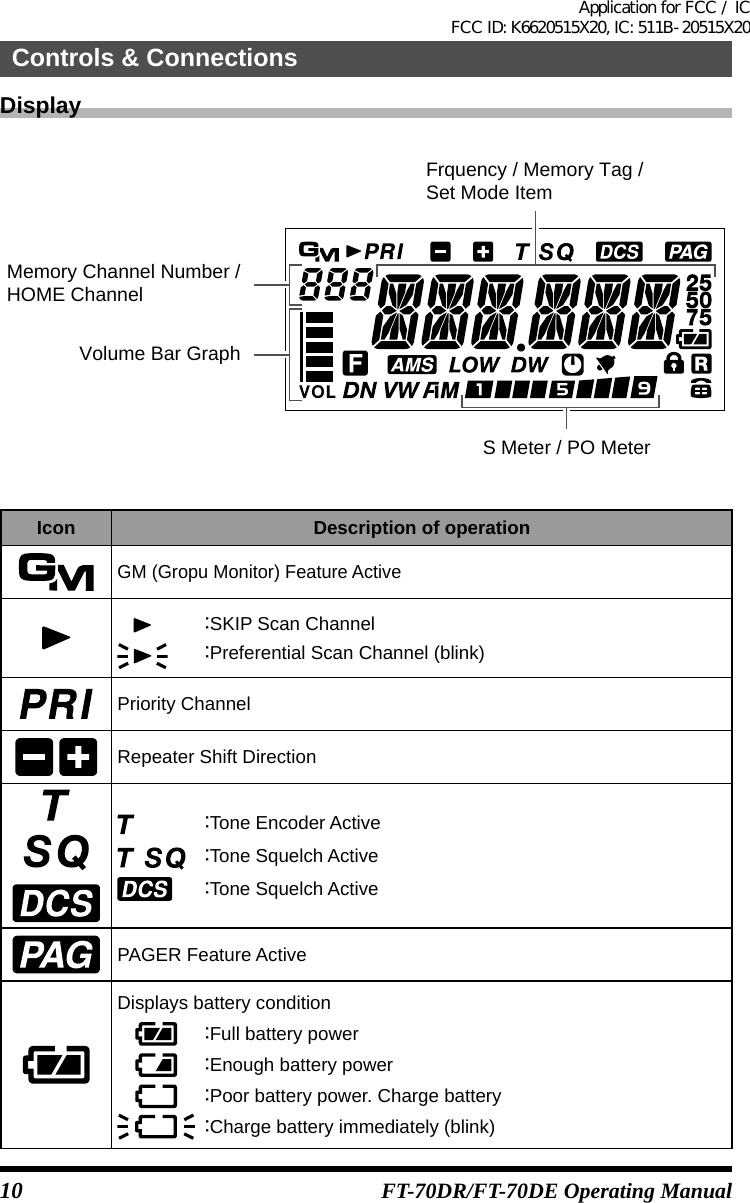
![6FT-70DR/FT-70DE Operating ManualTransceiver①②③④⑤⑥⑦⑧⑨⑩⑪⑫⑬⑭⑮⑯①Antenna Jack (SMA)*②LCD (Liquid Crystal Display)The display shows current operating conditions.③[PTT] switch•Press and hold [PTT] switch to transmit, and release it to receive.•In the Set mode, press this switch to save the new setting and return to normal operation.④Microphone⑤[MONI/T.CALL] SwitchUSA/EXP versionWhile [MONI/T.CALL] Switch is pressed: Squelch OFFEuropean versionWhile [MONI/T.CALL] Switch is pressed: T.CALL⑥[VOL] SwitchRotate the DIAL knob while pressing and holding this key to adjust the audio volume level.⑦ [Power] (Lock) Switch•When the power is off, press and hold: Power on•When the power is on, press and hold: Power off•When the power is on, press : Engages and releases the key lockControls & ConnectionsApplication for FCC / IC FCC ID: K6620515X20, IC: 511B-20515X20](https://usermanual.wiki/Yaesu-Musen/20515X20.Operating-Manual-2/User-Guide-3232554-Page-2.png)
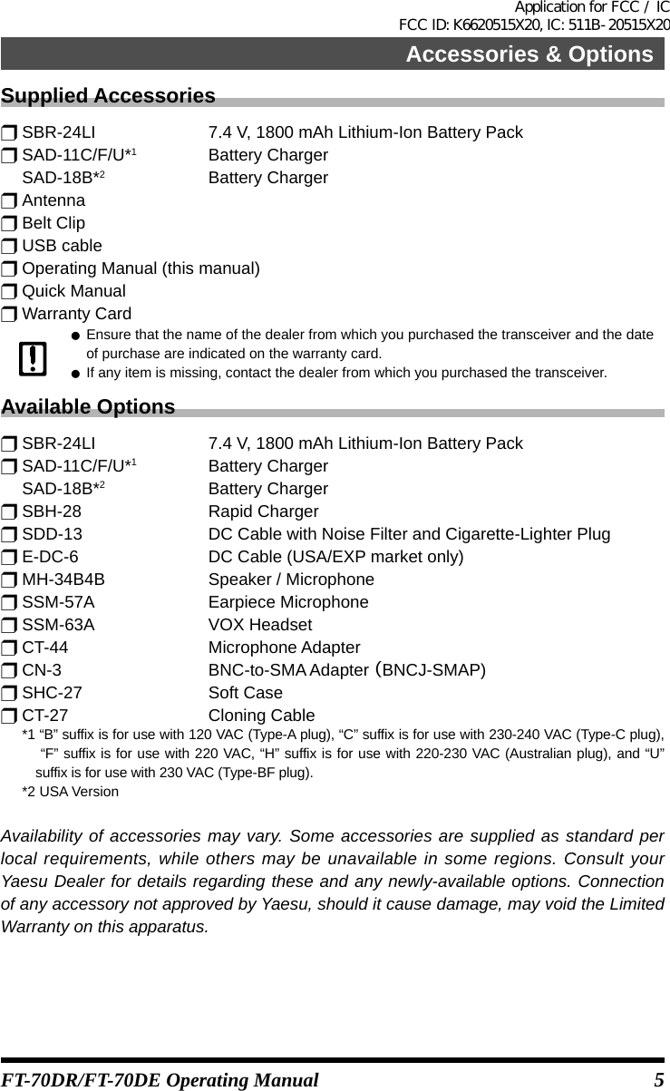
![8Controls & ConnectionsFT-70DR/FT-70DE Operating ManualKeyPrimary Function(PRESS Key) Secondary Func-tion(PRESS [F] + Key)Third Function(Press and Hold)VFO orMemory RecallInputting Memory TagAMS Activates the AMS feature -Selects AMS Mode (AUTO/MANUAL/FM FIX/DN FIX/VW FIX) -FActivates the “Sec-ondary”key function -Enters the Set mode.Deactivates the “Secondary”key functionMODESelects the re-ceive mode among FM(AM), DN and VWMoves the cursor to the left.Switches between the frequency dis-play and memory tag display-HM/RVRecall the “HOME” (favorite frequency) channel-Reverses the transmit and receive frequencies while working through a repeater-GM Turns on/off the GM functionPress and hold this key to erase all characters after the cursor-Selects the DG-ID or DP-IDBANDMoves operation to the next-highest frequency bandMoves the cursor to the rightMoves operation to the next-lowest fre-quency band-V/MSwitches between the VFO mode and Memory Channel modePress and hold [V/M] key to complete the memory channel registrationEnables the Dual Watch functionActivates the “Mem-ory Write” mode (for memory channel storage)1Number “1” Number “1” Selects the desired transmit power out-put level.-2Number “2” Number “2”, or char-acters “A”, “B”, or “C”Starts the scanner upward (toward a higher frequency or a higher channel number)-3Number “3” Number “3”, or char-acters “D”, “E”, or “F”Selects the DTMF mode. -4Number “4” Number “4”, charac-ters “G”, “H”, or “I”Selects the frequen-cy steps -5Number “5” Number “5”, charac-ters “J”, “K”, or “L”Activates the CTCSS or DCS operation-Application for FCC / IC FCC ID: K6620515X20, IC: 511B-20515X20](https://usermanual.wiki/Yaesu-Musen/20515X20.Operating-Manual-2/User-Guide-3232554-Page-4.png)
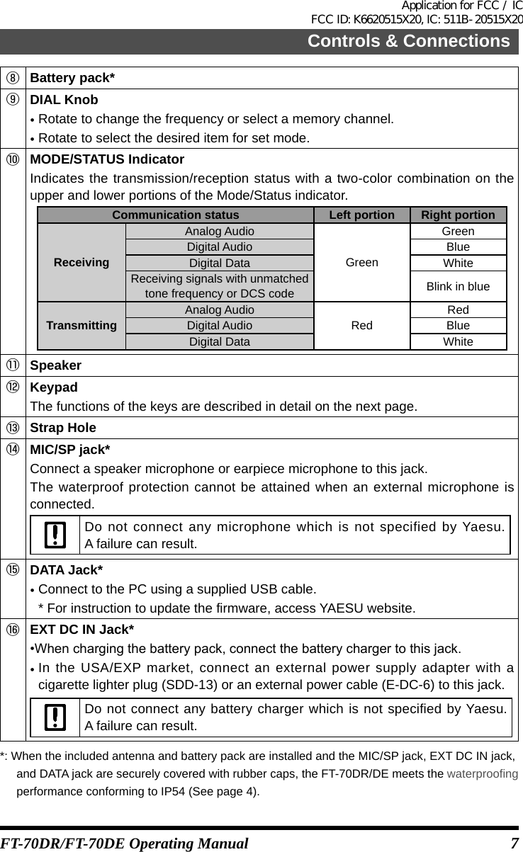
![9Controls & ConnectionsFT-70DR/FT-70DE Operating ManualKeyPrimary Function(PRESS Key) Secondary Func-tion(PRESS [F] + Key)Third Function(Press and Hold)VFO orMemory RecallInputting Memory Tag6Number “6” Number “6”, or characters “M”, “N”, or “O”Selects the CTCSS Tone or DCS code -7Number “7” Number “7”, or char-acters “P”, “Q”, “R”, or “S”P1* (Enters the Set mode [13 DC VLT])-8Number “8” Number “8”, or char-acters “T”, “U”, or “V”P2* (Enters theSet mode [57 RX MOD])-9Number “9” Number “9”, or char-acters “W”, “X”, “Y”, or “Z”Selects the Memory Scan “Skip” channel or “Select” channel-0Number “0” Number “0”, or sym-bols “(space)”, “-”, “/”, “?”, or “!”Selects the direction of the up link fre-quency shift (either “–”, “+”, or “simplex”) during repeater operation.Press and hold this key will fix the digits after the cursor with zeros during fre-quency input.*: You can program the secondary function of the key to another function.Application for FCC / IC FCC ID: K6620515X20, IC: 511B-20515X20](https://usermanual.wiki/Yaesu-Musen/20515X20.Operating-Manual-2/User-Guide-3232554-Page-5.png)