Yaesu Musen 20485X40 Amateur Radio with scanning receiver User Manual Operating Manual
Yaesu Musen Co., Ltd. Amateur Radio with scanning receiver Operating Manual
UserManual.wiki
>
Yaesu Musen
>
20485X40 User Manual
>
User Manual Part 2
Contents
1.
User Manual Part 1
2.
User Manual Part 2
User Manual Part 2
Navigation menu
Upload a User Manual
Namespaces
Wiki Guide
HTML
PDF
Info
Views
User Manual
Discussion / Help
Navigation
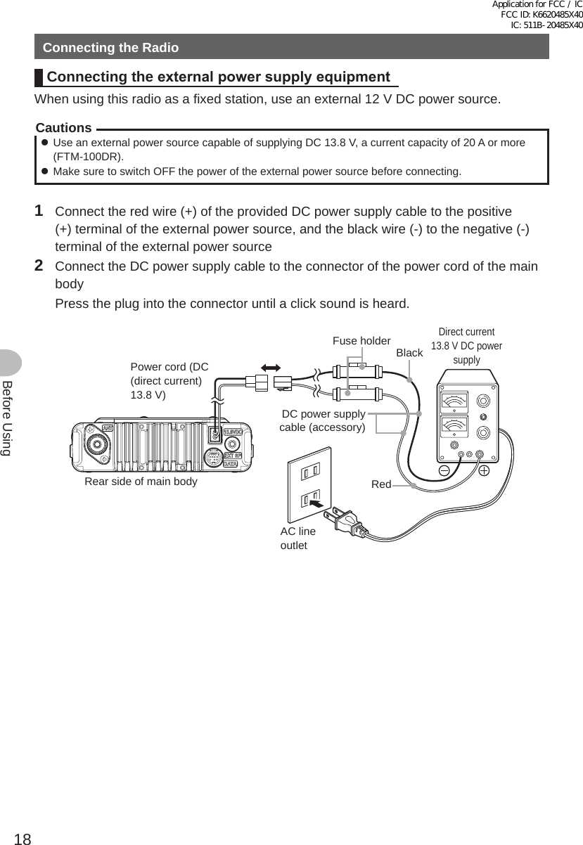
![17Before UsingConnecting the RadioConnecting the controller to the main bodyCautionMake sure the power supply is switched OFF before connecting the cable between the controller and the main body.1 Plug the connector of the controller cable into the [CONTROL] jack at the front of the main body until a click sound is heardMainbodyControllercable2 Plug the other connector of the controller cable into the [CONTROL] jack at the back of the controller until a click sound is heardController cableControllerConnecting the microphone1 Plug the microphone connector into the [MIC] jack at the front of the main body until a click sound is heard Tips • To remove the microphone, pull the connector out while pressing the latch. • Using the optional microphone extension kit “MEK-2”, a microphone with a 8-pin connector can be used. A microphone extension cable (about 3 m long) is also included in MEK-2. Use it to install the microphone in locations which cannot be reached by the attached microphone cable.LOCKP3P2P171482059BACD36P4LAMPDTMF MICROPHONEMH-48ABCJKLTUVGHIPQRSDEFMNOWXYZMICConnectorMicrophoneConnecting the antenna1 Attach the antenna co-axial cable to the [ANT] terminal at the back of the main body and tighten the connector同軸ケーブル端子本体(後面)Main body (rear side)Co-axial cable connectorApplication for FCC / IC FCC ID: K6620485X40 IC: 511B-20485X40](https://usermanual.wiki/Yaesu-Musen/20485X40.User-Manual-Part-2/User-Guide-2578124-Page-1.png)
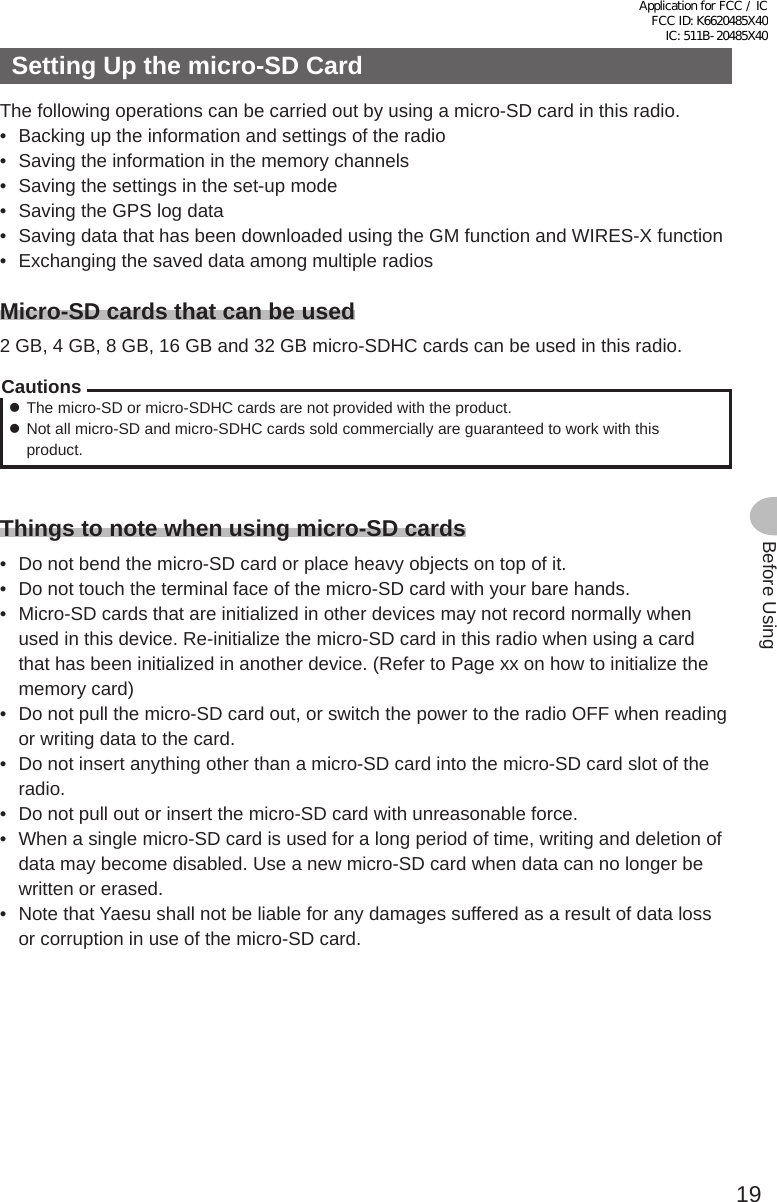
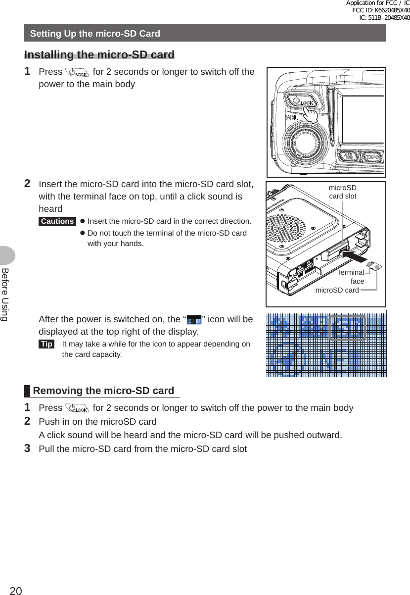
![21Before UsingSetting Up the micro-SD CardInitializing the micro-SD cardWhen using a new micro-SD card, initialize the micro-SD card according to the following procedure.CautionUpon initialization, all the data recorded in the micro-SD card will be erased. Check the contents of the micro-SD card before initialization.1 Press for one second or longer The set-up menu will be displayed.2 Turn the DIAL to select [11 SD], then press The menu list will be displayed.3 Turn the DIAL to select [4 FORMAT], then press The format confirmation screen will be displayed.4 Turn the DIAL to select [OK?], then press The micro-SD card will be initialized. Tip To cancel initialization, turn the DIAL to select [Cancel], then press . “Completed” will be displayed when initialization is completed and the screen will then return to the menu list.Application for FCC / IC FCC ID: K6620485X40 IC: 511B-20485X40](https://usermanual.wiki/Yaesu-Musen/20485X40.User-Manual-Part-2/User-Guide-2578124-Page-5.png)
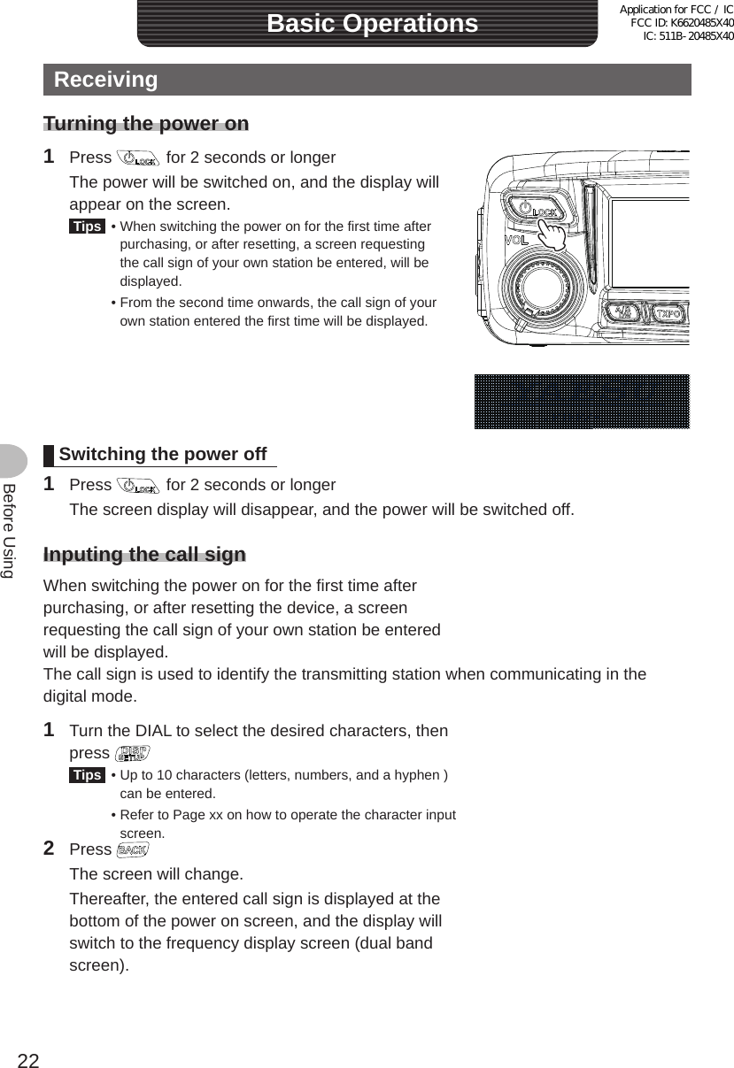
![24Before UsingReceivingAdjustingthesquelchlevelAnnoying noises can be muted when a signal cannot be detected. Band A and Band B squelch levels can be individually adjusted. Noise can be canceled more easily when the squelch level is increased but it may become more difficult to pick up weak signals. Adjust the squelch level as required.1 Press [SQL] The sub-band will be displayed, and the current squelch level will be displayed on the SQL meter.2 Turn the DIAL to adjust the squelch level The squelch level displayed on the sub-band display and the level displayed on the SQL meter will be changed. Tip If you do not perform any operation for 3 seconds after changing the meter display or turning the DIAL, the screen will return to the normal screen.Application for FCC / IC FCC ID: K6620485X40 IC: 511B-20485X40](https://usermanual.wiki/Yaesu-Musen/20485X40.User-Manual-Part-2/User-Guide-2578124-Page-8.png)
![25Before UsingReceivingTuning the radio ●Using the knobs1 Turn the DIAL The frequency will increase when the knob is turned in a clockwise direction and decrease when turned in a counter-clockwise direction. ●Using the microphone keys1 Press [UP] or [DWN] The frequency increases when [UP] is pressed, and decreases when [DWN] is pressed.UPDWNApplication for FCC / IC FCC ID: K6620485X40 IC: 511B-20485X40](https://usermanual.wiki/Yaesu-Musen/20485X40.User-Manual-Part-2/User-Guide-2578124-Page-9.png)
![26Before UsingCommunicatingTransmitting1 Press and hold the microphone [PTT] The top half of the indicator will light red.2 Talk directly into the microphone [MIC] Tip Keep the microphone at a distance of about 1 inch away from the mouth when talking.LOCKP3P2P171482059BACD36P4LAMPDTMF MICROPHONEMH-48ABCJKLTUVGHIPQRSDEFMICMNOWXYZPTTMICThe top half of the indicator will light red.3 Release [PTT] The red bar and PO meter level will disappear and the radio will return to the receiving state.Tips• Refrain from transmitting continuously for a long period of time as much as possible. The temperature of the main body will rise and this may result in burns and equipment failure due to overheating.• “ERROR TX FREQ” will be displayed when attempting to transmit on a frequency that is not in the amateur band.Application for FCC / IC FCC ID: K6620485X40 IC: 511B-20485X40](https://usermanual.wiki/Yaesu-Musen/20485X40.User-Manual-Part-2/User-Guide-2578124-Page-10.png)
![27Before UsingCommunicatingAdjustingthetransmitpowerWhen communicating with a nearby station, the transmit power can be reduced to save on energy consumption.1 Press Pressing each time switches the transmission power in the following order. “HI” → “LO” → “MD”Model HI MD LOFTM-100DR 0W 20W 5WAdjustingthesensitivityofthemicrophoneThe sensitivity (gain) of the microphone can be adjusted.1 Press for one second or longer The set-up menu will be displayed.2 Turn the DIAL to select [2 TX/RX], then press The menu list will be displayed.3 Turn the DIAL to select [2 MIC GAIN], then press The microphone gain setting value will be displayed.4 Turn the DIAL to select the desired microphone gain “1 MIN” → “2 LOW” → “3 NORMAL” → “4 HIGH” Tip Factory default value: NORMAL5 Press for one second or longer The sensitivity is set and the display returns to the previous screen. Tip You can also return to the previous screen by pressing 3 times.Application for FCC / IC FCC ID: K6620485X40 IC: 511B-20485X40](https://usermanual.wiki/Yaesu-Musen/20485X40.User-Manual-Part-2/User-Guide-2578124-Page-11.png)
![28Before UsingCommunicatingCommunicating in the FM mode1 Choose the operating band2 Select “MANUAL (FM)” as the modulation mode3 Turn the DIAL to tune in to the frequency4 Press and hold the microphone [PTT] to talkTipYou can also use the half deviation. From [2 TX/RX] → [8 HALF DEVIATION] in the set-up menu, select “ON”.Application for FCC / IC FCC ID: K6620485X40 IC: 511B-20485X40](https://usermanual.wiki/Yaesu-Musen/20485X40.User-Manual-Part-2/User-Guide-2578124-Page-12.png)