Yaesu Musen 20445X20 AMATEUR RADIO WITH SCANNING RECEIVER User Manual 8
Yaesu Musen Co., Ltd. AMATEUR RADIO WITH SCANNING RECEIVER 8
UserManual.wiki
>
Yaesu Musen
>
20445X20 User Manual
>
User Manual 8
Contents
1.
USERS MANUAL
2.
User Manual 1
3.
User Manual 2
4.
User Manual 3
5.
User Manual 4
6.
User Manual 5
7.
User Manual 6
8.
User Manual 7
9.
User Manual 8
User Manual 8
Navigation menu
Upload a User Manual
Namespaces
Wiki Guide
HTML
PDF
Info
Views
User Manual
Discussion / Help
Navigation
![125Functions Used As NeededSet ModeTurning illumination off when scanning stops SCAN LAMP FunctionYou can set the backlight of LCD to turn ON or OFF when a signal is received during scanning.Enter the Set mode:1 Press and hold M for over 1 second.2 Turn O to select [5 SCAN].3 Press H.4 Turn O to select [2 SCAN LAMP].5 Press H.6 Turn O to select [OFF]. ON: The LCD backlight will light when a signal is received. OFF: The LCD backlight will not light when a signal is received. Remark Default: ON7 Press p to save the backlight ON or OFF setting when scanning stops, and exit the Set mode.Setting the time to resume scan SCAN RE-START FunctionYou can set the time to resume scanning after a signal is received during scanning.Enter the Set mode:1 Press and hold M for over 1 second.2 Turn O to select [5 SCAN].3 Press H.4 Turn O to select [3 SCAN RE-START].5 Press H.6 Turn O to select the time to resume scanning. Select from 0.1 SEC to 10 SEC. Remark Default: 2 seconds7 Press p to set the resume scanning time, and exit the Set mode.䎃䎖 䎃䎶䎦䎤䎱䎃 䎃䎵 䎨䙵䎶 䎷 䎤 䎵 䎷䎃䎃䎃䎃 䎃 䎘 䎑 䎓䏖䏈䏆䎃䎖 䎃 䎶䎦䎤䎱䎃 䎃䎵 䎨䙵䎶 䎷 䎤 䎵 䎷䎗䎃䎶䎦䎤䎱䎃 䎃䎵 䎨䎶䎸䎰䎨䎃䎘 䎃䎶䎦䎤䎱䎃 䎃䎺 䎬 䎧䎷䎫䎃 䎔 䎃 䎧䎺䎃 䎃䎷 䎬 䎰䎨䎶䎨䎷䎝䎃䎃䎘䎃 䎶 䎦 䎤 䎱䎃䎃䎃䎃䎃䎃䎃䎃䎙 䎃䎪䎰䎃䎃䎃䎃䎃䎃䫹䎚 䎃䎺 䎬 䎵 䎨 䎶䙵䎻䎃䎃䎃䎃䎃䎃䎃䎃䎛 䎃 䎦䎲䎱 䎩 䎬 䎪䎃䎖 䎃䎶䎦䎤䎱䎃 䎃䎵 䎨䙵䎶 䎷 䎤 䎵 䎷䎃䎃䎃䎃 䎃 䎘 䎑 䎓䏖䏈䏆䎃䎖 䎃 䎶䎦䎤䎱䎃 䎃䎵 䎨䙵䎶 䎷 䎤 䎵 䎷䎗䎃䎶䎦䎤䎱䎃 䎃䎵 䎨䎶䎸䎰䎨䎃䎘 䎃䎶䎦䎤䎱䎃 䎃䎺 䎬 䎧䎷䎫䎃 䎔 䎃 䎧䎺䎃 䎃䎷 䎬 䎰䎨䎶䎨䎷䎝䎃䎃䎘䎃 䎶 䎦 䎤 䎱䎃䎃䎃䎃䎃䎃䎃䎃䎙 䎃䎪䎰䎃䎃䎃䎃䎃䎃䫹䎚 䎃䎺 䎬 䎵 䎨 䎶䙵䎻䎃䎃䎃䎃䎃䎃䎃䎃䎛 䎃 䎦䎲䎱 䎩 䎬 䎪Application for FCC / IC FCC ID: K6620445X20 IC: 511B-20445X20](https://usermanual.wiki/Yaesu-Musen/20445X20.User-Manual-8/User-Guide-2766372-Page-1.png)
![126Functions Used As NeededSet ModeSelecting a reception method when scanning stopsSet the reception method for when scanning stops.For more details, see “Selecting a Reception Method When Scanning Stops” on page P. 59.Setting the range for SCANYou can set the frequency range for scanning with the SCAN Function.Enter the Set mode:1 Press and hold M for over 1 second. 2 Turn O to select [5 SCAN].3 Press H.4 Turn O to select [5 SCAN WIDTH].5 Press H.6 Turn O to select [VFO].7 Press H.8 Turn O to select the range for scanning. Specify the scanning range with reference to the next list.9 Press M.10 Turn O to select [MEMORY].11 Press H.12 Turn O to select the range for scanning.Mode Display* Operation StatusVFO ModeALL Scans all bands within the range from the current frequency to 108-999 MHz.BAND Scans the current band (see the table on the next page) starting with the current frequency.Memory ModeALL CHScans all memory channels (1-900) of the currently selected memory channel. When selected memory channels are specified, all of them are scanned (See page 59).BANDScans only the memory channels to which frequencies in the same fre-quency band*1 are registered. When the selected memory channels are specified, scans only the selected memory channels to which frequencies in the same frequency band*1 are registered (See page 61).*1 For the relationship between frequency bands and reception frequencies, see the table at the bottom of page 28.13 Press p to save the range for scanning, and exit the Set mode.Application for FCC / IC FCC ID: K6620445X20 IC: 511B-20445X20](https://usermanual.wiki/Yaesu-Musen/20445X20.User-Manual-8/User-Guide-2766372-Page-2.png)
![127Functions Used As NeededSet ModeTurning off the power automatically APO FunctionThe transceiver may be set to turn off automatically if there is no operation for a certain period of time.Enter the Set mode:1 Press and hold M for over 1 second.2 Turn O to select [8 CONFIG].3 Press H.4 Turn O to select [1 APO].5 Press H.6 Turn O to set the time. Set the time for the transceiver to turn off automatically in steps of 30 minutes. OFF/30 MIN/1 HOUR to 12 HOURS Remark Default: OFF7 Press p to save the auto power-off function setting, and exit the Set mode. The transceiver will be automatically turned off if there is no operation for the set period of time.Tips• When the auto power-off function is active, the [ icon appears on the LCD.• Once the time for automatic power-off is set, it is retained until “OFF” is selected in step 6 of the above-mentioned procedure. (The next time you turn the transceiver on, if you perform no operation for the set pe-riod of time, the transceiver will automatically turn itself off.)Application for FCC / IC FCC ID: K6620445X20 IC: 511B-20445X20](https://usermanual.wiki/Yaesu-Musen/20445X20.User-Manual-8/User-Guide-2766372-Page-3.png)
![128Functions Used As NeededSet ModePreventing accidental transmission Busy Channel Lockout (BCLO) FunctionYou can prevent accidental transmission during signal reception.Enter the Set mode:1 Press and hold M for over 1 second.2 Turn O to select [8 CONFIG].3 Press H.4 Turn O to select [2 BCLO].5 Press H.6 Turn O to select [ON]. Remark Default: OFF7 Press p to save the BCLO function setting, and exit the Set mode.Muting the key operation confirmation toneThe operation confirmation sound (beep sound) that is heard when keys are operated, or when scanning reaches the end of a frequency band, can be turned off.Enter the Set mode:1 Press and hold M for over 1 second.2 Turn O to select [8 CONFIG].3 Press H.4 Turn O to select [3 BEEP].5 Press H.6 Turn O to select [SELECT].7 Press H.8 Turn O to select [OFF]. Remarks Default: KEY&SCANDisplay DescriptionOFF Mutes the beep.KEY&SCAN Emits a beep when a key is operated or scan-ning stops.KEY Emits a beep when a key is pressed.9 Press M.10 Turn O to select [EDGE].11 Press H.12 Turn O to select [OFF].13 Press p to exit from the Set mode.Application for FCC / IC FCC ID: K6620445X20 IC: 511B-20445X20](https://usermanual.wiki/Yaesu-Musen/20445X20.User-Manual-8/User-Guide-2766372-Page-4.png)
![129Functions Used As NeededSet ModeTurning off the BUSY IndicatorWhen you listen to the radio continuously or when the remaining battery level has become low, you can turn off the BUSY indicator to save battery power consumption.Enter the Set mode:1 Press and hold M for over 1 second.2 Turn O to select [8 CONFIG].3 Press H.4 Turn O to select [4 BUSY LED].5 Press H.6 Turn O to select a band. Select a band from among [A BAND], [B BAND], and [RADIO].7 Press H.8 Turn O to select [OFF]. Remark Default: ON9 Press p. The BUSY indicator is turned off, and exits from the Set mode.Setting the clock shift for the micro computer Clock Type FunctionThe micro computer Clock Shift function may be set to reduce internal high frequency spurious interference signals. Select [A] for normal use.Enter the Set mode:1 Press and hold M for over 1 second.2 Turn O to select [8 CONFIG].3 Press H.4 Turn O to select [5 CLOCK TYPE].5 Press H.6 Turn O to select a clock type. A: The Clock Shift function is automatically turned on or off. B: The Clock Shift function is continually active. Remark Default: A7 Press p to save the Clock Type setting, and exit the Set mode.Application for FCC / IC FCC ID: K6620445X20 IC: 511B-20445X20](https://usermanual.wiki/Yaesu-Musen/20445X20.User-Manual-8/User-Guide-2766372-Page-5.png)
![130Functions Used As NeededSet ModeSetting interval to save GPS position informationSet the interval at which the GPS information of your current position is saved to the microSD memory card.Enter the Set mode:1 Press and hold M for over 1 second.2 Turn O to select [8 CONFIG].3 Press H.4 Turn O to select [6 GPS LOG].5 Press H.6 Turn O to select an interval to save GPS position information. OFF / 1 SEC / 2 SEC / 5 SEC /10 SEC / 30 SEC / 60 SEC Information is not recorded to the microSD memory card if OFF is selected. Remark Default: OFF7 Press p to save the GPS information saving interval setting, and exit the Set mode.Tips• Data saved to the microSD memory card is saved in xxx.LOG format.• Saved data can be viewed with PC applications*.* PC applications are not supported by our company.Permitting Transfer of Home Channel Frequency to VFO You can use the set operation to transfer home channel frequency information to the VFO.Enter the Set mode:1 Press and hold M for over 1 second.2 Turn O to select [8 CONFIG].3 Press H.4 Turn O to select [7 HOME VFO].5 Press H.6 Turn O to select Unlock or Lock. ENABLE: Turning O in home channel transfers the home channel frequency to VFO. DISABLE: The home channel frequency cannot be transferred. Remark Default: ENABLE7 Press p to save the frequency transfer ENABLE/DISABLE/Unlock setting, and exit the Set mode.䎃䎚䎃䎃䎫䎲䎰䎨䎃䎃䎹䎩䎲䎃䎛䎃䎃䎯 䎨 䎧 䎃䎃 䎯 䎬 䎪䎫䎷䎃 䎜 䫹 䎯 䎲 䎦 䎮䎔䎓䫹 䎰 䎲䎱 䎬 䎒 䎷䙵䎦䎤䎯䎯䎃䎚䎃䎃䎫䎲䎰䎨䎃䎃䎹䎩䎲䎃 䎃䎃䎃 䎃䎃 䎃䎨䎱䎤䎥䎯䎨䎃䎃䎃䎶䎨䎷䎝䎃 䎃䎛 䫹 䎦 䎲 䎱 䎩 䎬 䎪䎃䎃䎃䎃䎃䎃䎃䎃䎜 䫹 䎤 䎳 䎵䎶䎃䎃䎃䎃䎃䎃䫹䎔䎓䫹 䎶 䎧䎃䎃䎦䎤䎵䎧䎃䎃䎃䎃䎃 䎃䎔䎔䫹 䎲 䎳 䎷 䎬 䎲 䎱Application for FCC / IC FCC ID: K6620445X20 IC: 511B-20445X20](https://usermanual.wiki/Yaesu-Musen/20445X20.User-Manual-8/User-Guide-2766372-Page-6.png)
![131Functions Used As NeededSet ModeUsing the White LED as a FlashlightThe white LED may be used as a flashlight.Enter the Set mode:1 Press and hold M for over 1 second.2 Turn O to select [8 CONFIG].3 Press H.4 Turn O to select [8 LED LIGT].5 Press H. The white LED lights as a flashlight.6 Press M. The LED goes out.7 Press p to exit from the Set mode.Setting the conditions for locking LOCK FunctionConditions for activating Lock Function, such as keys, O, and p, can be set.Enter the Set mode:1 Press and hold M for over 1 second.2 Turn O to select [8 CONFIG].3 Press H.4 Turn O to select [9 LOCK].5 Press H.6 Turn O to select the keys and switches to lock. KEY & DIAL: Locks the keys and O on the front of the transceiver. PTT: Locks p. KEY & PTT: Locks the keys and p on the front of the transceiver. DIAL & PTT: Locks O and p. ALL: Locks the keys, O, and p on the front of the transceiver. KEY: Locks the keys on the front of the transceiver. DIAL: Locks O. Remark Default: KEY&DIAL7 Press p. The keys and switches to lock are set, and exits from the Set mode.Application for FCC / IC FCC ID: K6620445X20 IC: 511B-20445X20](https://usermanual.wiki/Yaesu-Musen/20445X20.User-Manual-8/User-Guide-2766372-Page-7.png)
![132Functions Used As NeededSet ModeSetting the operation of The function for when T is pressed can be set.Enter the Set mode:1 Press and hold M for over 1 second.2 Turn O to select [8 CONFIG].3 Press H.4 Turn O to select [10 MONI/T-CALL].5 Press H.6 Turn O to select the function. MONI: Pressing T monitors frequency. T-CALL: Pressing T functions as tone call. Remark Default: Depends on the transceiver version.7 Press H. The function for T is set.8 Press p to save the setting and exit the Set mode. Turning on/off the transceiver at the specified time Timer FunctionYou can turn the transceiver to turn on/off at the set time. Before using this function, adjust the clock. See “Setting clock time” on page 34.Enter the Set mode:1 Press and hold M over 1 second.2 Turn O to select [8 CONFIG].3 Press H.4 Turn O to select [11 TIMER].5 Press H.6 Turn O to select [ON] or [OFF]. ON: Turns on the transceiver at the specified time. OFF: Turns off the transceiver at the specified time.7 Press H.8 Turn O to specify hours.9 Press H.10 Turn O to specify minutes.11 Press H.12 Turn O to switch between ON/OFF of the timer.13 Press M. The timer function is turned on.14 Press p to exit from the Set mode.Application for FCC / IC FCC ID: K6620445X20 IC: 511B-20445X20](https://usermanual.wiki/Yaesu-Musen/20445X20.User-Manual-8/User-Guide-2766372-Page-8.png)
![133Functions Used As NeededSet ModePassword FunctionYou can enter a 4-character password to prevent a third party from using your transceiver without permission. Once a password is entered, the transceiver cannot be turned on until the valid password is entered.Enter the Set mode:1 Press and hold M for over 1 second.2 Turn O to select [8 CONFIG].3 Press H.4 Turn O to select [12 PASSWORD].5 Press H.6 Press H.7 Turn O to enter the first character of the password. Enter the first character (0-9. A to D, , and #) of the password.8 Press H. The cursor moves to the next character position.9 Repeat steps 7 and 8 to enter the remaining three characters.10 Press H.11 Turn O to select [ON]. Remark Default: OFF12 Press p to save the password setting, and exit the Set mode.Tips• To cancel the password function, execute the above-mentioned steps 1 to 5, select “OFF” with O, and then press p over 1 second.• Keypad keys cannot be used to enter the password.• When the on-timer function is active, the password function is ineffective.Turning on the transceiver using a password1 Press and hold P for over 1 second. The password entry screen appears.2 Enter the password using keypad keys. Enter the registered 4-character password. When the valid password is entered, the frequency display screen appears. Remark When an invalid password is entered, the transceiver is turned off automatically.CautionIf you’ve forget the registered password, carrying out all resetting allows you to turn on the transceiver without entering the password.It should be noted that performing all resetting resets (initializes) all information such as the information registered to memory channels and various setting values.It is recommended that the password be written down on paper.Application for FCC / IC FCC ID: K6620445X20 IC: 511B-20445X20](https://usermanual.wiki/Yaesu-Musen/20445X20.User-Manual-8/User-Guide-2766372-Page-9.png)
![134Functions Used As NeededSet ModeSetting the PTT delay time PTT DELAY FunctionYou can set the time for actual transmission to start after p is pressed.Enter the Set mode:1 Press and hold M for over 1 second.2 Turn O to select [8 CONFIG].3 Press H.4 Turn O to select [13 PTT DELAY].5 Press H.6 Turn O to select the time. OFF/20ms/50ms/100ms/200ms Remark Default: OFF7 Press p to save the PTT delay time setting, and exit the Set mode.Setting the ARS function RPT ARS FunctionYou can set the operation of ARS (Tuning in to the repeater frequency automatically enables the repeater).Enter the Set mode:1 Press and hold M for over 1 second.2 Turn O to select [8 CONFIG].3 Press H.4 Turn O to select [14 RPT ARS].5 Press H.6 Turn O to select ON/OFF. ON: ARS is functional. OFF: ARS is not functional. Remark Default: ON7 Press p to save the ARS function ON/OFF setting, and exit the Set mode.Application for FCC / IC FCC ID: K6620445X20 IC: 511B-20445X20](https://usermanual.wiki/Yaesu-Musen/20445X20.User-Manual-8/User-Guide-2766372-Page-10.png)
![135Functions Used As NeededSet ModeSetting the direction for repeater shift RPT SHIFT FunctionYou can set the direction of repeater shift.Enter the Set mode:1 Press and hold M for over 1 second.2 Turn O to select [8 CONFIG].3 Press H.4 Turn O to select [15 RPT SHIFT].5 Press H.6 Turn O to select the shift direction. SIMPLEX: Does not shift. –RPT: Shifts toward lower frequencies. +RPT: Shifts toward higher frequencies. Remark Default setting differs depending frequency7 Press p to save the repeater shift direction setting, and exit the Set mode. Setting the range for repeater shift RPT SHIFT FREQ FunctionYou can set the repeater shift range.Enter the Set mode:1 Press and hold M for over 1 second.2 Turn O to select [8 CONFIG].3 Press H.4 Turn O to select [16 RPT SHIFT FREQ].5 Press H.6 Turn O to select shift range. The range can be set in steps of 50 kHz between 0.0000 MHz and 150.000 MHz. Pressing F and then turning O allows you to set frequencies in steps of 1 MHz. Remark Default setting differs depending frequency7 Press p to save the repeater shift range setting, and exit the Set mode.Application for FCC / IC FCC ID: K6620445X20 IC: 511B-20445X20](https://usermanual.wiki/Yaesu-Musen/20445X20.User-Manual-8/User-Guide-2766372-Page-11.png)
![136Functions Used As NeededSet ModeDisabling reception while no signal is received Reception Save FunctionTo reduce power consumption, the reception function can be turned off when not receiving a signal.Enter the Set mode:1 Press and hold M for over 1 second.2 Turn O to select [8 CONFIG].3 Press H.4 Turn O to select [17 SAVE RX].5 Press H.6 Turn O to select the time. Select the time for the reception to be turned off automatically. 0.2 SEC (1:1) to 1.0 SEC (1:5) (Step: 0.1 sec) to 1.0 SEC (1:5) to 10 SEC (1:50) (Step: 0.5 sec) to 1.0 sec (1:50) to 60 sec (1:300 sec) step 5 sec OFF Remark Default: 0.2 sec (1:1)7 Press p to save the Reception Save function setting, and exit the Set mode. Changing the frequency step manuallyFrequency step can be set so that it can be changed manually.For more details, see “Changing the Frequency Step Manually” on page 37.Setting clock timeSet the time for the internal clock of this transceiver.For details, see “Setting clock time” on page 34.Restricting the continuous transmission time TOT FunctionSet the transceiver to automatically return to the receive mode after transmitting continuously for a certain period of time. Accidental transmission of unnecessary signals, and unwanted battery power consumption can be prevented (time-out timer function).Enter the Set mode:1 Press and hold M for over 1 second.2 Turn O to select [8 CONFIG].3 Press H.䎔䎚䎃 䎃䎶䎤䎹䎨䎃䎃䎵䎻䎔䎛䎃 䎃䎶 䎷 䎨 䎳䎔䎜䫹䎧䎤䎷 䎨 䎃䎃 䎉䎃 䎃 䎷 䎬 䎰 䎨 䎃 䎃䎤䎧䎭䎕䎓䫹䎷䎲䎷䎔䎚䎃 䎃䎶䎤䎹䎨䎃䎃䎵䎻䎃 䎃䎃䎃 䎃䎃 䎃䎃䎃䎓 䎑 䎕䏖䏈䏆䎋 䎔 䎝 䎃䎔䎃 䎃 䎃䎌䎃䎶䎨䎷䎝䎃 䎃䎛 䫹 䎦 䎲 䎱 䎩 䎬 䎪䎃䎃䎃䎃䎃䎃䎃䎃䎜 䫹 䎤 䎳 䎵䎶䎃䎃䎃䎃䎃䎃䫹䎔䎓䫹 䎶 䎧䎃䎃䎦䎤䎵䎧䎃䎃䎃䎃䎃 䎃䎔䎔䫹 䎲 䎳 䎷 䎬 䎲 䎱Application for FCC / IC FCC ID: K6620445X20 IC: 511B-20445X20](https://usermanual.wiki/Yaesu-Musen/20445X20.User-Manual-8/User-Guide-2766372-Page-12.png)
![137Functions Used As NeededSet Mode4 Turn O to select [20 TOT].5 Press H.6 Turn O to select the time. Set the time for the transceiver to automatically return to the reception state in steps of 30 seconds. OFF/30 SEC to 10 MIN Remark Default: OFF7 Press p to save the TOT function setting, and exit the Set mode.Tips• When the time-out timer function is active, a beep is emitted when it comes near the set time. About 10 seconds later, the transceiver returns to the reception state.• Once the time is set, it is retained until “OFF” is selected in step 6 of the above-mentioned procedure.Setting the frequency selection range for operation in the VFO mode VFO MODE FunctionYou can set the frequency selection range for operating in the VFO mode.Enter the Set mode:1 Press and hold M over 1 second.2 Turn O to select [8 CONFIG].3 Press H.4 Turn O to select [21 VFO MODE].5 Press H.6 Turn O to select a frequency range. ALL: Switches to the next band when the end of a band is reached. BAND: Moves to the other end of the band when the end of that band is reached. Remark Default: BAND7 Press p to save the frequency selection range setting, and exit the Set mode.Application for FCC / IC FCC ID: K6620445X20 IC: 511B-20445X20](https://usermanual.wiki/Yaesu-Musen/20445X20.User-Manual-8/User-Guide-2766372-Page-13.png)
![138Functions Used As NeededSet ModeNotification of a call from a remote station by vibrationThe vibrator function may be set to notify you of a call from a remote station. For details, see “Notification of Call from the Remote Station by Vibration of the Vibrator” on page 88. Saving/ Loading data to/from microSD memory cardSettings information can be saved to a microSD memory card, also the saved information can be loaded to the transceiver.Enter the Set mode:1 Press and hold M over 1 second.2 Turn O to select [10 SD CARD].3 Press H.4 Turn O to select [1 BACKUP].5 Press H.6 Turn O to select [Write to SD] or [Read from SD]. Write to SD: Saves the setting information of your transceiver to the microSD memory card. Read from SD: Loads the setting information to your transceiver from the microSD memory card. Cancel: Stops save or load.7 Press H. [OK?] appears on the LCD.8 Press H. The write or read is performed and [Completed] appears when finished.9 Press p to exit from the Set mode. Saving/ Loading memory channel information to/from microSD memory cardMemory channel setting information can be saved to a microSD memory card, or saved information can be loaded to this transceiver.Enter the Set mode:1 Press and hold M for over 1 second.2 Turn O to select [10 SD CARD].3 Press H.Blinks when writingBlinks when writingApplication for FCC / IC FCC ID: K6620445X20 IC: 511B-20445X20](https://usermanual.wiki/Yaesu-Musen/20445X20.User-Manual-8/User-Guide-2766372-Page-14.png)
![139Functions Used As NeededSet Mode4 Turn O to select [2 MEMORY CH].5 Press H.6 Turn O to select [Write to SD] or [Read from SD]. Write to SD: A beep is heard and [Completed] appears when writing to SD finished. Read from SD: A beep is heard when loading from SD finished and the transceiver restarts with the settings read from the microSD memory card. (The operation in step 9 is not required.) Cancel: Stops save or load.7 Press H. [OK?] appears on the LCD.8 Press H. The write or read is performed and [Completed] appears when finished.9 Press p to exit from the Set mode.Saving/ Loading GROUP ID information to/from microSD memory cardGroup ID setting information can be saved to a microSD memory card, or saved informa-tion can be loaded to this transceiver.Enter the Set mode:1 Press and hold M for over 1 second.2 Turn O to select [10 SD CARD].3 Press H.4 Turn O to select [3 GROUP ID].5 Press H.6 Turn O to select [Write to SD] or [Read from SD]. Write to SD: Saves the Group ID information to your transceiver to the microSD memory card. Read from SD: Loads the Group ID information to your transceiver from the microSD memory card. Cancel: Stops save or load.7 Press H. [OK?] appears on the LCD.Blinks when writingBlinks when writingApplication for FCC / IC FCC ID: K6620445X20 IC: 511B-20445X20](https://usermanual.wiki/Yaesu-Musen/20445X20.User-Manual-8/User-Guide-2766372-Page-15.png)
![140Functions Used As NeededSet Mode8 Press H. Write to SD: A beep is heard and [Completed] appears when writing to SD finished. Read from SD: A beep is heard when loading from SD finished and the transceiver restarts with the settings read from the microSD memory card. (The operation in step 9 is not required.)9 Press p to exit from the Set mode.Formatting a microSD memory cardFormat a new microSD.For more details, see “Formatting a microSD memory card” on page 24.Setting the optional microphone with camera for useImage size and quality can be set for the optional microphone with camera (MH-85A11U).Enter the Set mode:1 Press and hold M for over 1 second.2 Turn O to select [11 OPTION].3 Press H.4 Turn O to select [1 USB CAMERA].5 Press H.6 Turn O to select [SIZE].7 Press H.8 Turn O to select an image size. 320×240 160×1209 Press H.10 Turn O to select [QUALITY].11 Press H.12 Turn O to select an image quality. LOW: Low image quality NORMAL: Intermediate image quality HIGH: High image quality13 Press p to exit from the Set mode.CautionIf image size is set to large or image quality is set to high, the data transmission time becomes longer.The transmission time varies depending on the content of an image.Blinks when writingApplication for FCC / IC FCC ID: K6620445X20 IC: 511B-20445X20](https://usermanual.wiki/Yaesu-Musen/20445X20.User-Manual-8/User-Guide-2766372-Page-16.png)
![141Functions Used As NeededSet ModeRegistering CALLSIGNThe CALLSIGN used in the digital mode can be registered with up to 10 alphanumeric characters.Enter the Set mode:1 Press and hold M for over 1 second.2 Turn O to select [12 CALLSIGN].3 Press H.4 Enter the characters using keypad keys. Enter a callsign using keypad keys with reference to the following table.Numeric key A, 0 (Alphanumeric)112ABC23DEF34GHI45JKL56MNO67PQRS78TUV89WXYZ900 Tip • Pressing H moves the cursor to the right. • Press the % to move the corsor back to the left. • Press the F to delete the letter or number at the current cursor position.5 Press H. The cursor moves.6 Repeat steps 4 and 5 to enter the CALLSIGN.7 Press p to save the CALLSIGN setting and exit the Set mode.Application for FCC / IC FCC ID: K6620445X20 IC: 511B-20445X20](https://usermanual.wiki/Yaesu-Musen/20445X20.User-Manual-8/User-Guide-2766372-Page-17.png)
![142Functions Used As NeededSet ModeUsing the transceiver for packet communicationYou can perform packet communication with your transceiver by connecting TNC (Terminal Node Controller) using an optional connection cable (CT-44).TNCSPGNDGND2 kΩ10 FǴMICMICEARPTTAfter TNC is connected, set the level of output to TNC by adjusting the sound volume level of your transceiver.Also adjust the level of input to your transceiver using the output level adjustment volume on the TNC (Input level cannot be adjusted on your transceiver)CautionWhen sending a vast volume of data, the transmission takes a longer time and the transceiver may be overheated.If the transmission is continued for a long time, the overheat prevention circuit will operate and the transmission power decreases. If the transmission is continued further, the transmission will be au-tomatically stopped to prevent the transceiver from overheating and consequently malfunctioning.The transceiver will return to the receive mode.When the transceiver returns to the receive mode after the overheat prevention circuit has operated, turn the transceiver off, or keep it in the receive mode until the temperature cools.Tips• Set the Receive Battery Save function to OFF during packet communication by selecting [8 CONFIG] → [17 SAVE RX] in the Set mode.• The reception can be interfered with a noise generated from PC.If the transceiver can not receive normally, disconnect it from the PC and reconnect it to the PC using a photocoupler or noise filter.• To connect the TNC and PC, refer to the TNC instruction manual.Application for FCC / IC FCC ID: K6620445X20 IC: 511B-20445X20](https://usermanual.wiki/Yaesu-Musen/20445X20.User-Manual-8/User-Guide-2766372-Page-18.png)
![143Functions Used As NeededSet ModeClone OperationData and various settings saved in your transceiver can be copied to another FT1XDR/DE transceiver.1 Turn off the power of both FT1XDR/DE transceivers and connect an optional clone cable (CT-168) to the DATA terminal of each transceiver.2 Press P while pressing F on each transceiver. The two transceivers are turned on and placed in the clone mode.3 Press % on the receiving side transceiver and B on the transmission side. Copying data starts. When copying starts, the display on the receiving transceiver changes from [--WAIT--] to [--RX--]. When data transmission begins from the sending transceiver, the data transmission indicator appears on the LCD, indicating the data transfer is in progress. The indicator appears on the receiving transceiver, as well when data reception starts. Tips When copying is completed, the reception side transceiver returns to the normal mode. The indication on the LCD of the transmission side transceiver returns from [--TX--] to [CLONE].4 Turn off the power of both transceivers and disconnect the clone cable.CautionWhen the [ERROR] appears on the LCD during data transfer, copying cannot be completed. Check the clone cable connection, and redo the clone operation from the beginning.Time data cannot be copied.Application for FCC / IC FCC ID: K6620445X20 IC: 511B-20445X20](https://usermanual.wiki/Yaesu-Musen/20445X20.User-Manual-8/User-Guide-2766372-Page-19.png)
![144Functions Used As NeededSet ModeConnecting an external deviceUsing the DATA terminal, the transceiver can support various functions by setting “GPS”, the internal GPS unit begins outputting the position information data. The position information of the transceiver can be transferred at approximately 1 second intervals to the computer so that the position of the transceiver can be displayed in real-time on programs such as map software.Tips• For properties such as communication speed and Input/Output between COM ports.• For more details, see the Set mode option, [9 APRS] → [17 COM PORT SETTING].Connecting to a PCConnecting a PC to the data terminal of the FT1XDR/DE using the PC Connection Cable (SCU-19) accessory will enable data transmission or updating firmware as described below.a. Transmit position location information received by the FT1XDR/DE internal GPS unit.By setting [OUTPUT] in [17 COM PORT SETTING] of Set mode option [9 APRS] to details on settings, see Set mode option [17 COM PORT SETTING] in the APRS Instruction Manual.• To show information, software operating with NMEA-0183 specified GGA and RMC sentence is required.b. FT1XDR/DE Firmware UpdatesWhen a new firmware update for the FT1XDR/DE is available, go to the YAESU homepage to download the programming data and update the FT1XDR/DE to its newest state. SCU-19(accessory)TipTo use the SCU-19, install a dedicated driver to the PC. For downloading the dedicated driver and installation manual, please go to the YAESU website homepage (http://www.yaesu.com).Application for FCC / IC FCC ID: K6620445X20 IC: 511B-20445X20](https://usermanual.wiki/Yaesu-Musen/20445X20.User-Manual-8/User-Guide-2766372-Page-20.png)
![145Functions Used As NeededSet ModeConnecting the FT1XDR/DE to external devicesPosition information data can be exchanged between commercially sold GPS receivers or other external devices by using the optional Data Cable (CT-170) or the Data Cable 2.5Φ (CT-176).CT-170 (option)TipConnect the Data Cable (CT-170) and the Data Output Cable (CT-176) by referring to the instruction manual for the GPS device to be used, and cable specifications on the next page.Data Cable (CT-170)①↓⑤⑥↓⑪①②③⑦ RXD (Serial data input [FT1XDR/DE ← External Equipment])① RXD (Serial data input [FT1XDR/DE ← External Equipment])⑧ TXD (Serial data output [FT1XDR/DE → External Equipment])② TXD (Serial data output [FT1XDR/DE → External Equipment])⑪ GND ③ GNDData Cable (2.5Φ) (CT-176)③①②③①②① RXD (Serial data input [FT1XDR/DE ← External Equipment])① TXD (Serial data output [FT1XDR/DE → External Equipment])② TXD (Serial data output [FT1XDR/DE → External Equipment])② RXD (Serial data input [FT1XDR/DE ← External Equipment])③ GND ③ GNDApplication for FCC / IC FCC ID: K6620445X20 IC: 511B-20445X20](https://usermanual.wiki/Yaesu-Musen/20445X20.User-Manual-8/User-Guide-2766372-Page-21.png)
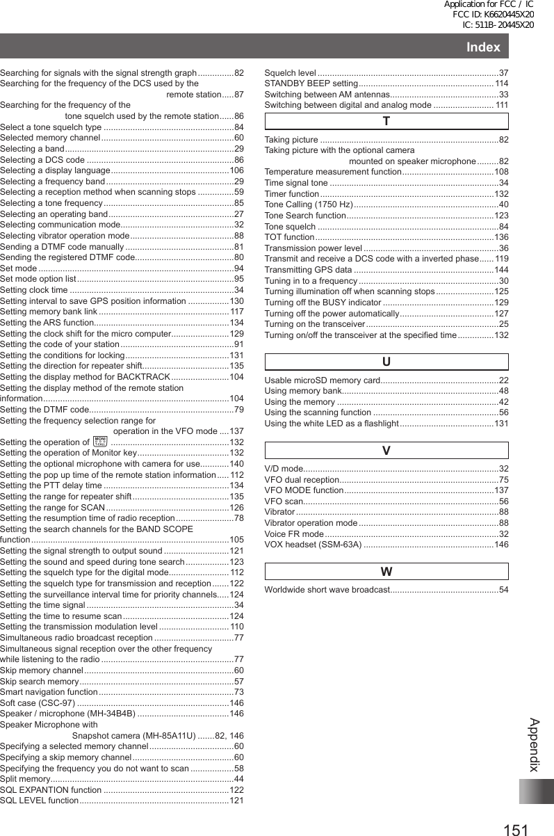
![152AppendixSpecificationsGeneralFrequency RangeA (Main) Band RX: 0.5 ~ 1.8 MHz (AM Radio)1.8 ~ 30 MHz (SW Radio)30 ~ 76 MHz (50 MHz HAM: USA version)30 ~ 88 MHz (50 MHz HAM: EXP/EU version)76 ~ 108 MHz (FM Radio: USA version)88 ~ 108 MHz (FM Radio: EXP/EU version)108 ~ 137 MHz (Air Band)137 ~ 174 MHz (144 MHz HAM)174 ~ 222 MHz (VHF Band)222 ~ 420 MHz (GEN1)420 ~ 470 MHz (430 MHz HAM)470 ~ 774 MHz (UHF Band: USA version)470 ~ 800 MHz (UHF Band: EXP/EU version)803 ~ 999 MHz (GEN2, Cellular Blocked: USA version)800 ~ 999 MHz (GEN2: EXP/EU version)B (Sub) Band RX: 108 ~ 137 MHz (Air Band)137 ~ 174 MHz (144 MHz HAM)174 ~ 222 MHz (VHF Band)222 ~ 420 MHz (GEN1)420 ~ 470 MHz (430 MHz HAM)470 ~ 580 MHz (UHF Band)TX: 144 ~ 146 MHz or 144 ~ 148 MHz430 ~ 440 MHz or 430 ~ 450 MHzChannel Steps: 5/6.25/8.33/9/10/12.5/15/20/25/50/100 kHzFrequency Stability: ±2.5 ppm (–20 °C to +60 °C [–4 °F to +140 °F])Emission Type: F1D, F2D, F3E, F7WSupply Voltage: Nominal: 7.4 V DC (Negative Ground)Operating: 4 – 14 V (Negative Ground, EXT DC JACK)11 – 16 V (Negative Ground, EXT DC JACK with SDD-13)7.4 V DC (Negative Ground)Current Consumption: 150 mA (Mono band Receive)220 mA (Dual band Receive)100 mA (Mono band Receive, Standby)150 mA (Dual band Receive, Standby)45 mA (Mono band Receive, Standby, Saver On “Save Ratio 1:5”)45 mA (Dual band Receive, Standby, Saver On “Save Ratio 1:5”)+30 mA (GPS On)+65 mA (Digital)600 μA (Auto Power Off)1.7 A (5 W TX, 144 MHz 7.4 V DC)2.0 A (5 W TX, 430 MHz 7.4 V DC)Operating Temperature: –20 °C to +60 °C [–4 °F to +140 °F]Case Size (W × H × D): 60 × 95 × 32.5 mm (2.4″ × 3.7″ × 1.28″) w/o knob & antennaWeight (Approx.): 290 g (10.23 oz) with SBR-14LI & AntennaApplication for FCC / IC FCC ID: K6620445X20 IC: 511B-20445X20](https://usermanual.wiki/Yaesu-Musen/20445X20.User-Manual-8/User-Guide-2766372-Page-28.png)