Yaesu Musen 20445X20 AMATEUR RADIO WITH SCANNING RECEIVER User Manual 6
Yaesu Musen Co., Ltd. AMATEUR RADIO WITH SCANNING RECEIVER 6
UserManual.wiki
>
Yaesu Musen
>
20445X20 User Manual
>
User Manual 6
Contents
1.
USERS MANUAL
2.
User Manual 1
3.
User Manual 2
4.
User Manual 3
5.
User Manual 4
6.
User Manual 5
7.
User Manual 6
8.
User Manual 7
9.
User Manual 8
User Manual 6
Navigation menu
Upload a User Manual
Namespaces
Wiki Guide
HTML
PDF
Info
Views
User Manual
Discussion / Help
Navigation
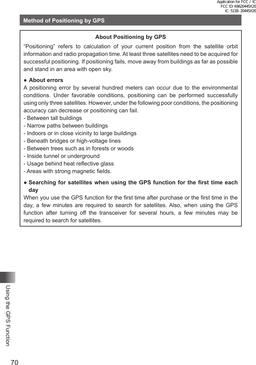
![71Using the GPS FunctionMethod of Positioning by GPSSaving GPS Information (GPS Log Function)Position information from the GPS can be saved periodically to the microSD memory card.Using the saved data and a personal computer, tracks can be displayed with commer-cially sold map software*.* Map software, and methods of use are not supported by YAESU.1 Check that the GPS function is active. If it is not active, refer to page 68 and enable the GPS function.2 Press M for over 1 second.3 Turn O to select [8 CONFIG].4 Press H.5 Turn O to select [6 GPS LOG].6 Press H.7 Turn O to select the interval for saving data. OFF / 1 sec / 2 sec / 5 sec / 10 sec / 30 sec / 60 sec Position information is not saved if OFF is selected.8 Press p to enable the GPS log function and exit from the Set mode.Tip• Position information will continue to be saved unless “OFF” is selected in step 7, shown above, or the power of the transceiver is turned off.• If “ON” is selected again in step 7, shown above, or the power for the transceiver is turned on, position information will start being saved to a differently named file.Checking Tracks on a PC1 Turn the transceiver off.2 Remove the microSD.3 Connect the microSD card to a PC using a commercially sold memory card reader.4 Open the folder named [FT1D] within the microSD memory card.5 Open the folder named [GPSLOG]. Data is saved with the name [GPSyymmddhhmmss.log]. The [yymmddhhmmss] part of the name represents year (yy), month (mm), day (dd), hour (hh), minute (mm), and second (ss).Tip• Tracks can be displayed on a personal computer using commercially sold map software by importing the GPS data.• For information on importing and using the GPS data, please refer to the operation manual for the map software being used.Application for FCC / IC FCC ID: K6620445X20 IC: 511B-20445X20](https://usermanual.wiki/Yaesu-Musen/20445X20.User-Manual-6/User-Guide-2766370-Page-2.png)
![72Using the GPS FunctionExplanation of GPS Screen and OperationActivating the GPS function displays the following information on the LCD.①②⑧③ ⑥ ⑦⑤ ④Press A to scroll the screen until the current time appears.① Compass: North-UP (North is always up)Heading-UP: Heading-UP: (When B is pressed, the direction in which you are heading is always up. A white arrow icon appears. [H] ap-pears at the lower right of the compass icon.② Positioning: When at least three satellites have been acquired, appears.This icon does not appear on the LCD if the transceiver cannot acquire at least three satellites.③ Number of satellites:Displays the number of acquired satellites.④ Latitude: The current position appears using north (N) or south (S) latitude.Display format: X DD° MM. MMM X: X=N: North latitude, X=S: South latitude DD: Degree MM.MMM: MinuteExample: N 35° 38.250 (35 degrees, 38 minutes, 15 sec-onds north latitude)⑤ Longitude: The current position appears using east (E) or west (S) longitude.Format: X DDD° MM. DMMM X: X=E: East longitude, X=W: West longitude DDD: Degree MM.MMM: MinuteExample: E 139° 42.500 (139 degrees, 42 minutes, 30 seconds east latitude)⑥ Speed: The speed at which you are moving appears.Format: SPD aaakm/hExample: SPD 5 km/h⑦ Altitude: The altitude of the current position of your radio station appears.Format: ALT aaaaamExample: ALT 20m⑧ Time: The current time set by GPS appears.Format: aa (hour): bb (minute): cc (second)Example: 23:59:59 (23 hours 59 minutes 59 seconds)* When an external GPS device is connected to the data terminal, the time appears as follows: aa (hour): bb (minute)Application for FCC / IC FCC ID: K6620445X20 IC: 511B-20445X20](https://usermanual.wiki/Yaesu-Musen/20445X20.User-Manual-6/User-Guide-2766370-Page-3.png)
![73Using the GPS FunctionExplanation of GPS Screen and OperationTips• You can change the unit of GPS data by selecting [9 APRS] → [22 GPS UNIT] in the Set mode.• When the GPS function is used, the accurate time data (date and time) obtained from GPS appears on a 24 hour basis. This time data is reflected in the time data displayed on the GPS and APRS screens.• You can change the geodetic system of the built-in GPS unit by selecting [9 APRS] → [19 GPS DATUM] in the Set mode. However, since APRS uses the geodetic system of WGS-84, it is recom-mended not to change it.• You can set the time zone by units of 30 minutes by selecting [9 APRS] → [28 TIME ZONE] in the Set mode (Default: UTC +0:00).• When the GPS function is active, the power consumption increases by about 30 mA. As a result, the battery life is reduced by about 20% compared to when the GPS function is deactivated.• You can obtain position information from a external GPS device by selecting [9 APRS] → [17 COM PORT SETTING] and then setting [INPUT] to [GPS] in the Set mode. In this case, the data obtained from the internal GPS is disabled.• When using an external GPS device, keep it away from the transceiver.Smart Navigation FunctionUsing the Smart Navigation FunctionThere are 2 methods of navigation with the Smart Navigation function.(1) Real-time navigation function(2) Backtrack functionReal-Time Navigation FunctionGPS position information and voice signals are simultaneously transmitted in the V/D mode of C4FM digital.For this reason, the position and direction of the remote station can be displayed in real-time even during communication.1 Press M to open the GPS screen.2 Turn O to select [YR]. The distance and direction to the remote station operating on the same frequency in the V/D mode is displayed.Display of remote station positionDistance to remote stationDirection display3 Press M. The screen returns from the navigation screen to the normal frequency display.Application for FCC / IC FCC ID: K6620445X20 IC: 511B-20445X20](https://usermanual.wiki/Yaesu-Musen/20445X20.User-Manual-6/User-Guide-2766370-Page-4.png)
![74Using the GPS FunctionSmart Navigation FunctionBacktrack FunctionBy registering a point of departure beforehand, the distance and direction to the regis-tered position from your current position can be displayed in real-time.Registering your current position (point of departure) (up to 3 positions can be registered)1 Press M to open the Backtrack screen.2 Turn O to select [MY].3 Press H to display the position information of your station.4 Turn O to select a mark to register from [I], [L1], and [L1].5 Press H to register the position information to the select-ed mark and return to the BACK TRACK function screen.6 Press M to return from the backtrack screen to the normal frequency display.Using the Backtrack Function1 Press M to open the Backtrack screen.2 Turn O to select [I], [L1] or [L2]. Select the mark with the registered position you would like to backtrack. The registered position (departure point) is in the direction of the arrow within the circle. Walk forward so that the arrow stays pointing up on the screen.3 Press M to return from the backtrack screen to the normal frequency display. To verify the position again, press [DISP] to open the backtrack screen.Description of the BACK TRACK Function ScreenDistance to the registered positionRegistered position markDirection to the registered positionApplication for FCC / IC FCC ID: K6620445X20 IC: 511B-20445X20](https://usermanual.wiki/Yaesu-Musen/20445X20.User-Manual-6/User-Guide-2766370-Page-5.png)
![75Convenient FunctionsConvenient FunctionsDual Reception (DW) FunctionThe FT1XDR/DE is equipped with the following 3 types of Dual Reception Functions:(1) VFO Dual Reception(2) Memory Channel Dual Reception(3) Home Channel Dual ReceptionThe transceiver checks the standby side signal reception over the frequency registered to the selected memory channel (Priority Memory Channel) once approximately every 5 seconds. When the transceiver detects signal reception on the standby side, it starts sig-nal reception over the frequency registered to the selected memory channel.Even while receiving a signal over the frequency registered to a priority memory channel on the standby side, pressing p disables the Dual Reception function and allows for transmission over the former active side frequency.Example: Checking signal reception over a frequency registered to the priority memory channel [90] (standby side), while receiving signal over [145.500 MHz] (active side).Frequency over which a signal is being received.The transceiver monitors signal re-ception over the frequency registered to the Priority Memory Channel [90] (standby) and checks it in intervals of approximately 5 seconds.When the transceiver receives a signal over the frequency registered to the pri-ority memory channel [90], dual recep-tion stops and signal reception switches to [90] (standby).VFO Dual Reception VFO mode → Priority memory channel1 Switch to the Memory mode.2 Press and hold F for over 1 second to enter the Write mode; F and the channel number blink on the LCD.3 Turn O to select a memory channel, then press and hold B for over 1 second. Select a memory channel to prioritize for signal reception (Priority Memory Channel). The “P” appears on the LCD.4 Turn O to select a frequency for signal reception. Select a frequency for continual signal reception in VFO mode (active side).5 Press F and then V to start Dial Dual Reception, and [VDW] appears on the LCD.6 Press V stop the Dial Dual Reception.“P” is displayed.“VDW” is displayed.Application for FCC / IC FCC ID: K6620445X20 IC: 511B-20445X20](https://usermanual.wiki/Yaesu-Musen/20445X20.User-Manual-6/User-Guide-2766370-Page-6.png)
![76Convenient FunctionsDual Reception (DW) FunctionMemory Channel Dual Reception Memory channel → Priority memory channel1 Switch to the Memory mode.2 Press and hold F over 1 second to enter the Write mode;F and the channel num-ber blink on the LCD.3 Turn O to select a memory channel and press B. Select a memory channel to prioritize for signal reception (Priority Memory Channel) (standby side). The “P” appears on the LCD.4 Select a memory channel for signal reception. Select a memory channel for signal reception at all times (active side).5 Press F and then V to start Memory Channel Dual Re-ception; and [MDW] appears on the LCD.6 Press V to stop the memory channel dual reception.Home Channel Dual Reception Home channel → Priority memory channel1 Switch to the Memory mode.2 Press and hold F over 1 second to enter the Write mode. F and the channel number blink on the LCD.3 Turn O to select a memory channel and press B. Select a memory channel to prioritize for signal reception (Priority Memory Channel) (standby side). The “P” appears on the LCD.4 Press F and then 4 to recall a HOME channel (active side).5 Press F and then V. HOME Channel Dual Reception starts and [MDW] appears on the LCD.6 Press V to turn home channel dual reception OFF.“P” is displayed.“MDW” is displayed.“P” is displayed.“HDW” is displayed.Application for FCC / IC FCC ID: K6620445X20 IC: 511B-20445X20](https://usermanual.wiki/Yaesu-Musen/20445X20.User-Manual-6/User-Guide-2766370-Page-7.png)
![77Convenient FunctionsDual Reception (DW) FunctionCautionBe sure to set a memory channel as the Priority Memory Channel for standby before using this function.Tips• The Priority Memory Channel is set to the Memory Channel number 1 by default.• Pressing and holding M over 1 second and changing the Set mode option allows you to use this function more conveniently.[5 SCAN] → [1 DW TIME]: The interval for monitoring the Priority Memory Channel can be changed.[5 SCAN] → [4 SCAN RESUME]: The resumption conditions for Dual Reception can be changed.• The combination of the frequency bands and modes of the frequency for the Priority Memory Channel (standby side) and the frequency for continual signal reception (active side) can be freely changed.AF-DUAL Function for simultaneous signal reception over the oth-er frequency while listening to the radioThe AF-DUAL Reception Function allows reception of a radio broadcast, while standby reception of A-band or B-band frequency (or frequency registered to a memory channel) is active. When standby reception is active, voice received over that frequency cannot be heard, however if a voice signal is detected, the reception of the radio broadcast will be paused and voice will be heard. Although there is a similar function in Dual Reception (See page 76), because a signal reception over the frequency registered to the priority memory channel is checked approximately every 5 seconds in Dual Reception, the recep-tion for radio broadcast is interrupted every time this happens. With the AF-DUAL Recep-tion Function, the reception of radio broadcast is interrupted only when there is a calling signal from another transceiver.Listening Radio Broadcast with AF-DUAL Reception Function1 Set the A-band or B-band frequency (or Memory Channel/Home Channel) for stand-by. Set the standby reception frequency for A-band or B-band (or Memory Channel/ Home Channel) to monitor for calls while receiving radio broadcast. Tips • You can listen to radio broadcast while scanning the standby signal reception frequencies. • Radio broadcast can be listened to while monitoring the standby signal reception frequency in the dual reception mode.2 Press A to set the operating band to A-band.3 Press F and then 6 to activate the AF-Dual function.4 Press B and select [AM] or [WFM]. The broadcast band is toggled in the following order every time B is pressed: AM broadcast (middle wave band) ⇔ FM broadcast ⇔ AM broadcast (middle wave band) On the LCD, AM (AM broadcast) or WFM (FM broadcast) is displayed.5 Turn O to tune in to the frequency of broadcast station.Application for FCC / IC FCC ID: K6620445X20 IC: 511B-20445X20](https://usermanual.wiki/Yaesu-Musen/20445X20.User-Manual-6/User-Guide-2766370-Page-8.png)
![78Convenient FunctionsDual Reception (DW) FunctionTips• For broadcast station frequencies, refer to “Preset Broadcast Station Frequencies List (See page 54)” or a commercially sold frequencies list.• AF-DUAL reception function can be used for the radio frequency registered to the memory bank.• Pressing T while a signal is being received, will switch to receiving the standby reception frequency.• With the AF-DUAL Function, an A Band or B Band registered with a AM broadcast (middle wave frequency) or a FM broadcast frequency, set for standby reception, cannot be simultaneously received while listening to the radio. • To disable the AF-DUAL Function, press F and then 6.The frequency registered to the standby (memory channel) appears on the LCD.Setting the resumption time of radio receptionWhile receiving radio broadcast (active side) and ham radio band (A-band or B-band) on standby side, the transceiver may be set to resume receiving the broadcast audio [After loss of receive signal] or [After transmission].1 Press and hold M for over 1 second to enter the Set mode.2 Turn O to select [2 TX/RX].3 Press H.4 Turn O to select [3 AUDIO].5 Press H.6 Turn O to select [3 RX AF DUAL].7 Press H.8 Turn O to select reception time. Set transmission time as well. Transmission and reception for 1 second to 10 seconds, HOLD (Fixed), or transmission for 1 second to 10 seconds. Remarks Default setting: transmission and reception for 2 secondsDisplay OperationTransmission and re-ception: 1 second to 10 secondsWhile receiving radio broadcast and ham radio band frequencies (A-band and B-band) on standby simultaneously with [AF-DUAL Reception Func-tion], resumption of receiving radio broadcast can be set to [After loss of receive signal] or [After transmission]. For example, if 5 seconds is selected, radio reception resumes after 5 seconds after reception (or transmission) ends.Fixed While receiving radio broadcast and ham radio band frequencies (A-band and B-band) on standby simultaneously with [AF-DUAL Reception Func-tion], the transceiver will continue to receive a signal over that frequency after signal detection without switching back to radio broadcast.Application for FCC / IC FCC ID: K6620445X20 IC: 511B-20445X20](https://usermanual.wiki/Yaesu-Musen/20445X20.User-Manual-6/User-Guide-2766370-Page-9.png)
![79Convenient FunctionsDual Reception (DW) FunctionDisplay OperationTransmission: 1 sec-ond to 10 secondsWhile receiving radio broadcast and ham radio band frequencies (A-band and B-band) on standby simultaneously with [AF-DUAL Reception Func-tion], the transceiver switches signal reception to the standby upon detect-ing it. After the user transmits signal for response and transmission ends, the transceiver switches signal reception back to radio broadcast after the specified time from the end of transmission. If a signal is received before transmitting it, [AF-DUAL Reception Function] is disabled and the transceiv-er continually receives a signal over that frequency.9 Press p to set the radio broadcast resumption time for reception and Transmission, and exit the Set mode.Using the DTMF FunctionDTMF (Dual Tone Multi Frequencies) is the tone signal sent for making a call through DTMF telephone line. The maximum of 16 digit DTMF code can be registered (up to 10 channels) for telephone numbers to make a call through the public telephone line from a phone patch.1 Press and hold M for over 1 second to enter the Set mode.2 Turn O to select [4 SIGNALING].3 Press H.4 Turn O to select [5 DTMF SELECT].5 Press H.6 Turn O to select a memory channel to register the DTMF code (1 to 10).7 Press H.8 Input the DTMF code with O. Tips • DTMF code can also be entered with the numeric keys. • To delete a code, press F. When F is pressed, a code is deleted and the cursor moves to left.9 Press H to move the cursor. 10 Repeat steps 8 and 9 to enter the DTMF code. Tips The maximum of 16 digits for DTMF code can be entered.䎃 䎖 䎃 䎵 䎻 䎃 䎤 䎩 䎃 䎧 䎸䎤䎯䎃䎃䎃䎃 䎃 䎷 䎵 䎻 䎃 䎕䏖 䏈 䏆䎃䎶䎨䎷䎝䎃䎃䎕 䎃 䎷 䎻 䎒 䎵 䎻䎃䎃䎃䎃䎃䎃䎃䎃䎖 䎃䎰䎨䎰䎲䎵䎼䎃䎃䎃䎃䎃䎃䎃䎃䎗 䎃 䎶 䎬 䎪 䎱 䎤 䎯 䎬 䎱䎪䎃䎃䎃䎃䎃䎃䎃䎃䎘 䎃 䎶䎦䎤䎱䎖 䎃 䎤 䎸 䎧 䎬 䎲䎔䎃䎰䎲䎧䎨䎃 䎕 䎃䎧 䎬 䎪 䎬 䎷 䎤 䎯䎖 䎃 䎵 䎻 䎃䎤 䎩 䎃䎧䎸䎤䎯䎗䎃䎹䎲䎯䎃䎰䎲䎧䎨䎃 䎔 䎃䎰 䎬 䎦 䎃 䎪 䎤 䎬 䎱䎃䎕䎃䎃䎰䎸䎷䎨Application for FCC / IC FCC ID: K6620445X20 IC: 511B-20445X20](https://usermanual.wiki/Yaesu-Musen/20445X20.User-Manual-6/User-Guide-2766370-Page-10.png)
![80Convenient FunctionsUsing the DTMF Function 11 Press p to set the DTMF code and exit from the Set mode.Confirming the entered DTMF code by the sound1 Press and hold M for over 1 second to enter the Set mode.2 Turn O to select [4 APRS].3 Press H.4 Turn O to select [5 SCAN].5 Press H.6 Turn O to select the memory channel to which the DTMF code was registered.7 Press F to confirm the registered DTMF code by the audio tones. 8 Press p to exit from the Set mode.Sending the Registered DTMF Code1 Press and hold M over 1 second to enter the Set mode. 2 Turn O to select [4 SIGNALING].3 Press H.4 Turn O to select [4 DTMF MODE].5 Press H.6 Turn O to select [MODE].7 Press H.8 Turn O to select [AUTO].9 Press M.10 Press p to set the auto dialer.11 While pressing p key, press 1 to 0 to select the DTMF memory channel to transmit with the numeric keys. Tips • The registered DTMF code is transmitted. • The transmitted DTMF tone can be heard from the speaker.12 Release p. Even if p is released, the DTMF tone signal will continue to be transmitted until trans-mission of the signal is complete.Application for FCC / IC FCC ID: K6620445X20 IC: 511B-20445X20](https://usermanual.wiki/Yaesu-Musen/20445X20.User-Manual-6/User-Guide-2766370-Page-11.png)
![81Convenient FunctionsUsing the DTMF Function Sending a DTMF Code Manually1 Press and hold M for over 1 second to enter the Set mode.2 Turn O to select [4 SIGNALING].3 Press H.4 Turn O to select [4 DTMF MODE].5 Press H.6 Turn O to select [MODE].7 Press H.8 Turn O to select [MANUAL].9 Press M.10 Press p to set [MANUAL].11 While pressing p, select the DTMF code to transmit by pressing 1 to 0, A, B, C, , and # on the numeric keys. Tips • The DTMF code selected by pressing the keys is transmitted (refer to chart below). • The transmitted DTMF tone can be heard from the speaker.12 Release p. Even if p is released, the DTMF tone signal will continue to be transmitted until trans-mission of the signal is complete.Tips• The DTMF code is a combination of 2 frequencies.1209Hz 1336Hz 1477Hz 1633Hz697Hz 1 2 3 A770Hz 4 5 6 B852Hz 7 8 9 C941Hz 0 # DApplication for FCC / IC FCC ID: K6620445X20 IC: 511B-20445X20](https://usermanual.wiki/Yaesu-Musen/20445X20.User-Manual-6/User-Guide-2766370-Page-12.png)
![82Convenient FunctionsSearching for signals with the signal strength graph. Band Scope FunctionWhile in VFO mode, the Band Scope Function is available that will graphically display the strength of the signals on up to ±50 channels, centered on the current main band frequency.1 Turn O to tune in to your desired center frequency.2 Press and hold B for over 1 second. With the current frequency as the center, the strengths of any signals of each of the higher and lower 16 channels are shown on a graph.3 Turn O to adjust the ▼ to point to any of the displayed channels, and the signal on the indicated frequency can be received. 4 Press B to exit the band scope function.Tips• You can change the number of band scope channels setting by selecting [1 DISPLAY] → [4 BAND SCOPE] in the Set mode. The band scope channel setting can be changed to ±5 channels, ±9 channels, ±16 channels, ±24 channels, and ±50 channels, instead of ±16 channels.• The band scope channel interval is the same as the VFO frequency step.• When band scope is active, the numeric keys will not function.• The audio of A/B common frequency band can be heard simultaneously while scanning.• FULL: Continualy scans(scoops).1Time: Scans(scoops) only once.If the frequency is changed with O, scan will resume. * FULL is only selected in the analog mode. * 1Time is only selected in the digital mode.Taking picture with the optional camera mounted on speaker microphonePictures can be taken by connecting the speaker microphone with optional camera (MH-85A11U).Captured image data can be saved to a microSD memory card placed in the transceiver.Saved image data can be sent to another transceiver in the digital mode or using the GM function.In addition, image data can be transmitted to other transceivers* by pressing the (Send Image Button] on the camera mounted on speaker microphone.* Refer to the Yaesu homepage or catalog for the models of transceiver to which images can be transferred.* Only the picture just taken can be sent to another transceiver. For methods to send other image data, refer to the GM Function instruction manual.Application for FCC / IC FCC ID: K6620445X20 IC: 511B-20445X20](https://usermanual.wiki/Yaesu-Musen/20445X20.User-Manual-6/User-Guide-2766370-Page-13.png)
![83Convenient FunctionsTaking picture with the optional camera mounted on speaker microphone.Send Image ButtonA picture just taken can be sent.LensAim this lrns towards the object to photograph.Do not touch the lens with fingers or other objects.PTT SwitchPress this button to transmit, and release it for reception.SpeakerSound is emitted from here.Shutter ButtonPress this button to take a picture.MicrophoneSpeak into here with a normal voice.ClipSecurely clip the microphone to belt or other objects.ConnectorConnector to connect the speaker microphone with camera to the transceiverPay attention to the alignment of connector when connecting the speaker microphone with camera to the ranceiver.Connecting it forcibly to the transceiver may cause damage.1 Connect the speaker microphone with camera (MH-85A11U) to the DATA terminal of the transceiver.2 Press P to turn the transceiver on.3 Press . Point the lens towards the object to shoot and press . Make sure to have at least 50cm between the lens and the object. If the object is too close, the picture will be out of focus, resulting in a blurred picture. Tips • You can set the picture size (resolution) and image quality (compression rate) of the image, by selecting [11 OPTION] → [1 USB CAMERA] in the Set mode. • Captured images are saved to the microSD memory card installed in the transceiver. • If your transceiver and another compatible transceiver are both in digital mode, a picture just taken may be sent to the other transceiver by pressing .CautionDo not directly photograph objects with strong light, such as the sun or other bright objects. Such operation can lead to malfunction.If the lens or the microphone gets dirty, use a dry, soft cloth to wipe off the contaminants.Do not place the MH-85A11U near heat emitting equipment or where it is exposed to direct sunlight. Doing so can lead to fire or a malfunction.Do not drop the MH-85A11U. Applying a strong shock to the MH-85A11U may result in damages or failure.Application for FCC / IC FCC ID: K6620445X20 IC: 511B-20445X20](https://usermanual.wiki/Yaesu-Musen/20445X20.User-Manual-6/User-Guide-2766370-Page-14.png)
![84Communicating with a Specific Remote StationCommunicating with a Specific Remote StationUsing the Tone Squelch FunctionThe tone squelch opens the squelch only when a signal containing the specified frequen-cy tone is received. Use of the digital code squelch (DCS) opens the squelch only when a signal containing the specified DCS code is received. The tone squelchfunction mutes monitoring the communications between other stations, even when listen-ing for a call by a specific station for a long time.1 Press and hold M over 1 second.2 Turn O to select [4 SIGNALING].3 Press H.4 Turn O to select [11 SQL TYPE].5 Press H. The Set mode option [11 SQL TYPE] is selected.6 Turn O to select a squelch type. Select a squelch type with reference to the table shown be-low.7 Press p to set the squelch type and exit the Set mode.Tips• The tone squelch and DCS setting are also active during scanning. If scanning is performed with the tone squelch or the DCS function turned on, it stops only when a signal containing a tone of the speci-fied frequency or a signal containing the specified DCS code is received.• Pressing the Monitor switch allows you to hear signals that do not contain a tone or DCS code, and signals with different tones or DCS code.• Pressing and holding M for 1 second, and then changing the Set mode option allows you to use this function more conveniently.[4 SIGNALING] → [3 DCS INVERSION]: Allows you to receive the DCS code of the inverted phase.[4 SIGNALING] → [10 SQL EXPANTION]: Allows you to specify different squelch types for transmis-sion and reception respectively.Display OperationOFF Turns off the tone sending function, tone squelch function, etc.TONE Just sends tones ([TN] appears).TONE SQL Turns on the tone squelch function ([TSQ] appears).DCS Turns on the digital code squelch ([DCS] appears).REV TONETurns on the reverse tone ([RTN] appears). Used to monitor communi-cations based on the squelch control system in which a tone signal is contained when communication is not performed and the tone signal dis-appears when communication starts.Displays squelch typeDisplays logoApplication for FCC / IC FCC ID: K6620445X20 IC: 511B-20445X20](https://usermanual.wiki/Yaesu-Musen/20445X20.User-Manual-6/User-Guide-2766370-Page-15.png)
![85Communicating with a Specific Remote StationUsing the Tone Squelch FunctionDisplay OperationPR FREQTurns on the no-communication squelch function for radios ([PR] ap-pears.). You can specify no-communication signal tone frequencies within the range from 300 Hz to 3000 Hz in steps of 100 Hz. PAGER (See page 90)Turns on a new pager function ([PAG] appears). When using transceivers with your friends, specifying personal codes (each code is composed of two tones) allows only a specific station to be called.D CD* Sends a DCS code only in case of transmission ([DC] appears).TONE-DCS* Sends a tone signal in case of transmission, and waits for a DCS code in case of reception ([T-D] appears).D CD-TONE SQL* Sends a DCS code in case of transmission, and waits for a tone signal in case of reception ([D-T] appears).* Pressing and holding M over 1 second and selecting [4 SIGNALING] → [10 SQL EXPANTION] and then [ON] will add the setting items of D CD, ONE-DCS, and D CD TONESQ to [10 SQL TYPE] of the Set mode option [4 SIGNALING], allowing you to select different types of squelches for transmission and reception.Selecting a Tone FrequencyYou can select a tone frequency from among 50 frequencies (67.0 Hz to 254.1 Hz).1 Specify the operating frequency.2 Press and hold M over 1 second. Enters the Set mode.3 Turn O to select [4 SIGNALING].4 Press H.5 Turn O to select [12 TONE SQL FREQ].6 Press H.7 Turn O to select a tone frequency.8 Quickly press M 3 times to save the tone frequency setting and exit the Set mode.Tips• The tone frequency selected using the above-described procedure is also effective when only the tone is sent out.• By default, the tone frequency is set to 88.5 Hz.Application for FCC / IC FCC ID: K6620445X20 IC: 511B-20445X20](https://usermanual.wiki/Yaesu-Musen/20445X20.User-Manual-6/User-Guide-2766370-Page-16.png)
![86Communicating with a Specific Remote StationUsing the Tone Squelch FunctionSearching for the Frequency of the Tone Squelch Used by the Remote StationThe frequency of the tone squelch used by the remote station can be searched for and displayed.Enter the Set mode:1 Press and hold M for over 1 second.2 Turn O to select [4 SIGNALING].3 Press H.4 Turn O to select [11 SQL TYPE].5 Press H.6 Turn O to select [TONE SQL].7 Press M.8 Turn O to select [12 TONE SQL FREQ].9 Press H.10 Receive the signal from the remote station.11 Press and hold B over 1 second. [TONE SEARCH] appears.12 Release B. Search for the tone frequency starts. When a corresponding tone frequency is detected, a beep is emitted and search stops temporarily. The detected tone frequency blinks. Tip To set the searched tone frequency and exit from the Set mode: Press B → a beep is emitted. → Quickly press M 3 times.TipFor the operation to perform when scan stops, refer to “Selecting a Reception Method When Scanning Stops” on page 59.Selecting a DCS CodeYou can select a DCS code from among 104 DCS codes (023 to 754).1 Specify the operating frequency.2 Press and hold M over 1 second to enter the Set mode.3 Turn O to select [4 SIGNALING].4 Press H.5 Turn O to select [2 DCS CODE].6 Press H.Application for FCC / IC FCC ID: K6620445X20 IC: 511B-20445X20](https://usermanual.wiki/Yaesu-Musen/20445X20.User-Manual-6/User-Guide-2766370-Page-17.png)
![87Communicating with a Specific Remote StationUsing the Tone Squelch Function7 Turn O to select a DCS code.8 Quickly press M 3 times to set the DCS code and exit from the Set mode.TipBy default, the DCS code is set to [023].Searching for the Frequency of the DCS Used by the Remote StationThe DCS code used by the remote station can be searched for and displayed.Enter the Set mode:1 Press and hold M over 1 second.2 Turn O to select [4 SIGNALING].3 Press H.4 Turn O to select [11 SQL TYPE].5 Press H.6 Turn O to select [DCS]. Sets the DCS.7 Press M.8 Turn O to select [2 DCS CODE].9 Press H.10 Receive the signal from the remote station.11 Press and hold B over 1 second. [DCS SEARCH] appears.12 Release B. Searching for the DCS code begins. When a correspond-ing DCS code is heard, a beep is emitted and search stops temporarily. The found DCS code blinks. Tip To set the searched DCS code: Press B → a beep is emitted. → Quickly press M 3 times to set the DCS code and exit from the Set mode.TipTo perform the operation when scan stops, refer to “Selecting a Reception Method When Scanning Stops” on page 59.Application for FCC / IC FCC ID: K6620445X20 IC: 511B-20445X20](https://usermanual.wiki/Yaesu-Musen/20445X20.User-Manual-6/User-Guide-2766370-Page-18.png)
![88Communicating with a Specific Remote StationUsing the Tone Squelch FunctionNotification of Call from the Remote Station by Vibration of the VibratorSet the vibrator to alert you of a call from a remote station containing a corresponding CTCSS tone or DCS code. Enter the Set mode:1 Press and hold M over 1 second.2 Turn O to select [8 CONFIG].3 Press H.4 Turn O to select [22 VIBRATOR].5 Press H.6 Turn O to select [MODE].7 Press H.8 Turn O to select [SIGNALING].9 Press p to set the Vibrator mode and exit the Set mode. Tip To turn off the Vibrator function, select [OFF] in step 7.Tips• The vibrator function can be set for all frequency bands belonging to A-band (Main) and B-band (Sub).• Selecting [8 CONFIG] → [22 VIBRATOR] → [MODE] and then [BUSY] for [MODE] in the Set mode will cause the vibrator to start vibrating when the BUSY LED lights upon reception of a signal.• If the BUSY state is not held continuously over 5 seconds, the sus-pended state is canceled.If the p switch is operated to change the communication mode from transmission to reception when the vibrator is turned ON, the vibrator function is turned off for 5 sec-onds.Selecting Vibrator Operation ModeEnter the Set mode:1 Press and hold M over 1 second.2 Turn O to select [8 CONFIG].3 Press H.4 Turn O to select [22 VIBRATOR].5 Press H.Application for FCC / IC FCC ID: K6620445X20 IC: 511B-20445X20](https://usermanual.wiki/Yaesu-Musen/20445X20.User-Manual-6/User-Guide-2766370-Page-19.png)
![89Communicating with a Specific Remote StationUsing the Tone Squelch Function6 Turn O to select [SELECT].7 Press H.8 Turn O to select a vibrator operation mode. Remark Default: MODE1MODE1 The vibrator vibrates continuously.MODE2 The vibrator operates at long intervals.MODE3 The vibrator operates at short intervals.9 Press p. Sets the Vibrator mode and exits from the Set mode.Notification of a Call from a Remote Station by the BellSet the Bell sound and the blinking b icon on the LCD, to alert you of a call from a remote station containing a corresponding CTCSS tone or DCS code. Enter the Set mode:1 Press and hold M over 1 second.2 Turn O to select [4 SIGNALING].3 Press H.4 Turn O to select [1 BELL].5 Press H.6 Turn O to select [SELECT].7 Press H.8 Turn O to select [BELL]. When the tone squelch or DCS function is turned on, the b icon appears.9 Press p to set the bell function and exit Set mode. Tip To turn off the bell function, select [OFF] in step 6.Tips• To use the bell function, turn on the tone squelch or DCS function.• The bell function cannot be used via the repeater.• The b icon appears when the bell function is turned on.Upon receipt of a signal from a remote station, the b icon blinks.Changing the Number of Times the Bell RingsEnter the Set mode:1 Press and hold M over 1 second.2 Turn O to select [4 SIGNALING].3 Press H.䎔䎃䎃䎥䎨䎯䎯䎃 䎃 䎶䎨䎯䎨䎦䎷䎃䎃䎃䎝䎃䎃䎥䎨䎯䎯䎃 䎃 䎵 䎬 䎱 䎪 䎨 䎵 䎃 䎝䎃䎃 䎔 䎃 䎃䏗 䏌 䏐䏈䎔䎃䎃䎥䎨䎯䎯䎃 䎃 䎶䎨䎯䎨䎦䎷䎃䎃䎃䎝䎃䎃䎥䎨䎯䎯䎃 䎃 䎵 䎬 䎱 䎪 䎨 䎵 䎃 䎝䎃䎃 䎔 䎃 䎃䏗 䏌 䏐䏈Application for FCC / IC FCC ID: K6620445X20 IC: 511B-20445X20](https://usermanual.wiki/Yaesu-Musen/20445X20.User-Manual-6/User-Guide-2766370-Page-20.png)
![90Communicating with a Specific Remote StationUsing the Tone Squelch Function4 Turn O to select [1 BELL].5 Press H.6 Turn O to select [RINGER].7 Press H.8 Turn O to select the number of times the bell rings. Remark Default: Once Tip You can select the number of times the bell rings from among 1 to 20 times, or continuous.9 Press p to set the selected number of times the bell rings and exit from the Set mode.Calling Only a Specific Station New Pager FunctionWhen using the transceivers with your friends, specifying personal codes (each code composed of two CTCSS tones) allows you to call only a specific station. Even if the called person is not near his or her transceiver, the information on the LCD indicates that he or she has been called.ACBMr. C sends the personal code of Mr. B.Three persons A, B, and C are using the transceiver.Only Mr. B is called.I’m going to call Mr. B. Ring, ring, ringFlow of Operation to Use the Pager FunctionSet the same code as that of the remote station.Determine a frequency.Perform transmission/reception.Confirm reception according to the information on the LCD and the bell sound.䎔䎃䎃䎥䎨䎯䎯䎃 䎃 䎶䎨䎯䎨䎦䎷䎃䎃䎃䎝䎃䎃䎥䎨䎯䎯䎃 䎃 䎵 䎬 䎱 䎪 䎨 䎵 䎃 䎝䎃䎃 䎔 䎃 䎃䏗 䏌 䏐䏈Application for FCC / IC FCC ID: K6620445X20 IC: 511B-20445X20](https://usermanual.wiki/Yaesu-Musen/20445X20.User-Manual-6/User-Guide-2766370-Page-21.png)
![91Communicating with a Specific Remote StationUsing the Tone Squelch FunctionSetting the Code of Your StationSet the personal code (your code) to be called by other stations.Enter the Set mode:1 Press and hold M over 1 second.2 Turn O to select [4 SIGNALING].3 Press H.4 Turn O to select [6 PAGER].5 Press H.6 Turn O to select [CODE-RX].7 Press H.8 Turn O to select a code. Select the first code from among 1 to 50.9 Press H. The cursor [] moves.10 Turn O to select a code. Select the second code from among 1 to 50. Caution The second code must be different from the first code.11 Press p to set your station code and exit from the Set mode. Tips • Default: 05 47 • The first and second codes contained in your personal code may be reversed, i.e., [47 05] from [05 47] but recognized as the same code. • If the same personal code (group code) is specified for all per-sons, all persons can be called at the same time.Turning on the New Pager FunctionEnter the Set mode:1 Press and hold M over 1 second.2 Turn O to select [4 SIGNALING].3 Press H.4 Turn O to select [11 SQL TYPE].5 Press H.6 Turn O to select [PAGER].7 Press p to set the new pager function and exit from the Set mode. You can make a call, or wait for a call from a remote station, using the new pager function.PAG appears.Application for FCC / IC FCC ID: K6620445X20 IC: 511B-20445X20](https://usermanual.wiki/Yaesu-Musen/20445X20.User-Manual-6/User-Guide-2766370-Page-22.png)
![92Communicating with a Specific Remote StationUsing the Tone Squelch FunctionCalling a Specific StationEnter the Set mode:1 Press and hold M over 1 second.2 Turn O to select [4 SIGNALING].3 Press H.4 Turn O to select [11 SQL TYPE].5 Press H.6 Turn O to select [PAGER]. Set the new pager function:7 Press M.8 Turn O to select [6 PAGER].9 Press H.10 Turn O to select [CODE-TX].11 Press H.12 Turn O to select the code of the remote station. Select the first code of the remote station. Caution Register the pager code of the remote station in advance.13 Press H. The cursor [] moves.14 Turn O to select the code of the remote station. Select the second code of the remote station.15 Press p to set the code of the remote station and exit from the Set mode.16 Press p to call the remote station.PAG appears.Application for FCC / IC FCC ID: K6620445X20 IC: 511B-20445X20](https://usermanual.wiki/Yaesu-Musen/20445X20.User-Manual-6/User-Guide-2766370-Page-23.png)
![93Communicating with a Specific Remote StationUsing the Tone Squelch FunctionBeing Called by the Remote Station (Standby Operation)If you use the new pager function on the same frequency as the remote station, the [PAG] icon displayed on the LCD changes to [PIN], alerting that you have been called by the remote station. In addition, if you turn on the “bell function” (See page 89), you can con-firm a call from the remote station by the [PAG] display, the blinking [b] icon, and the bell sound. Also, if you turn on the “vibrator function” (See page 88), the vibrator will confirm a call from the remote station.TipSelecting [4 SIGNALING] → [9 PAGER ANS-BACK] → [ON] in the Set mode automatically places the transceiver in the transmission mode (for about 2.5 seconds) when called by the remote party, and noti-fies the remote party to get ready for communication. When calledBlinksApplication for FCC / IC FCC ID: K6620445X20 IC: 511B-20445X20](https://usermanual.wiki/Yaesu-Musen/20445X20.User-Manual-6/User-Guide-2766370-Page-24.png)
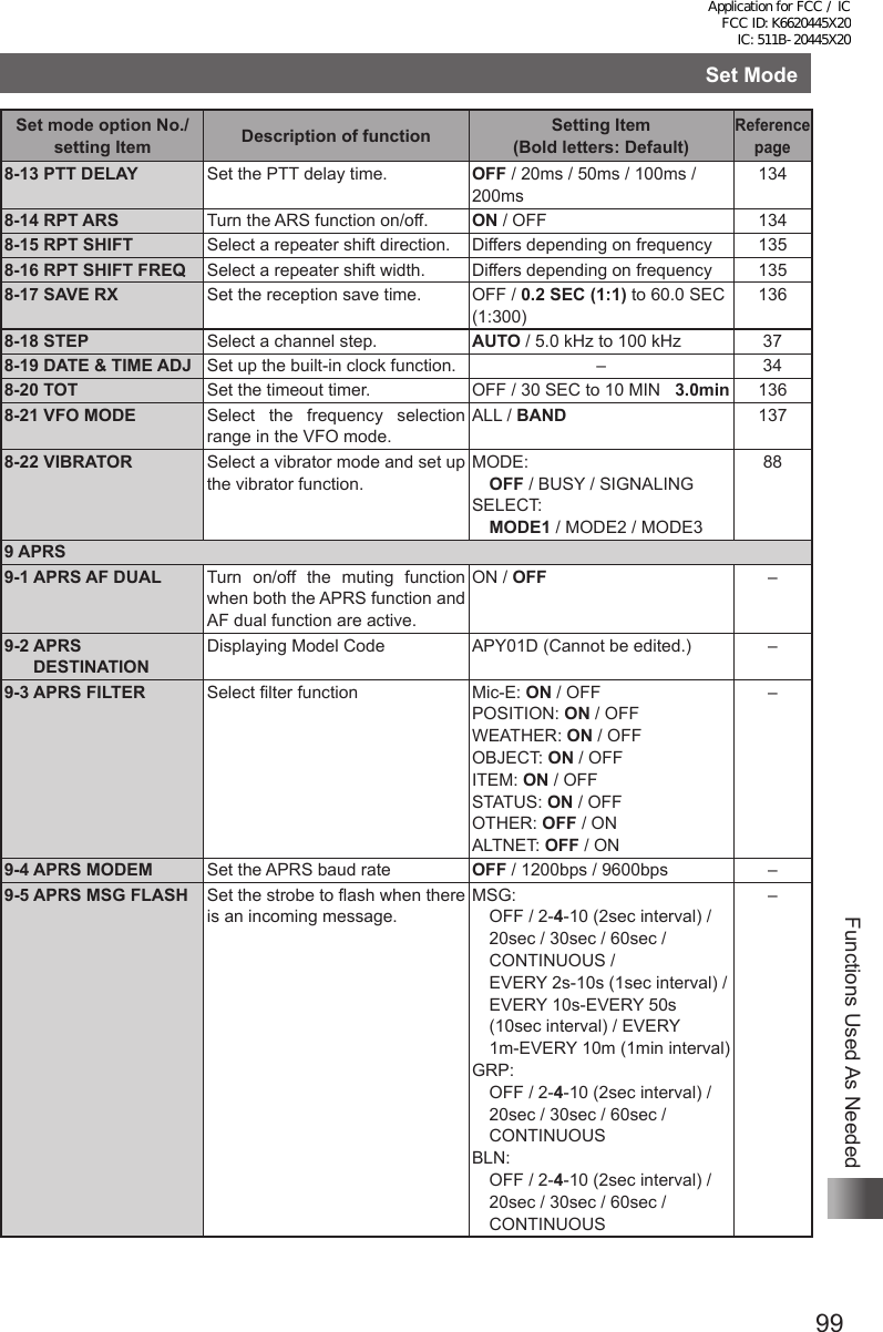
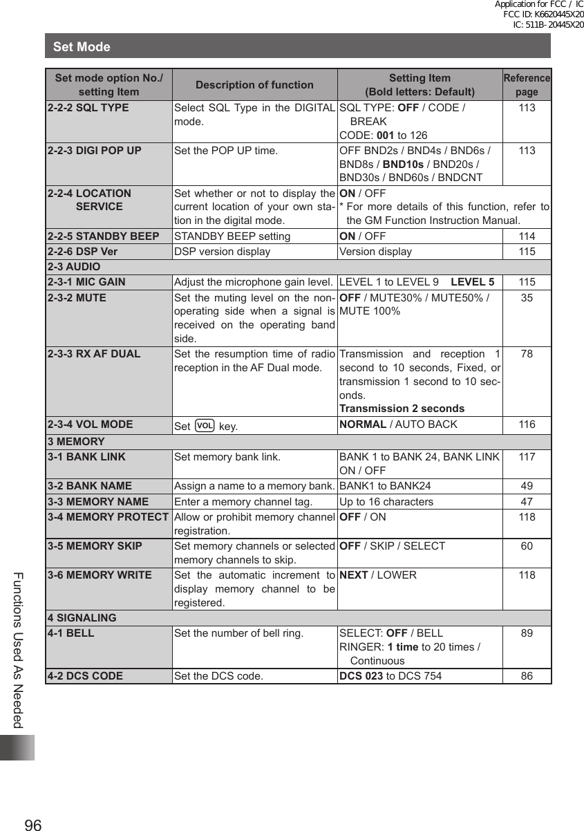
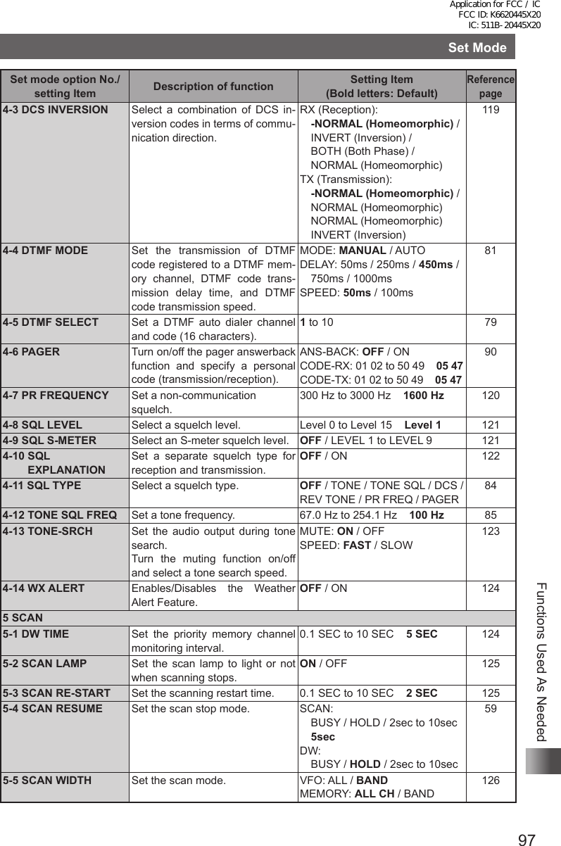
![94Functions Used As NeededFunctions Used As NeededSet ModeUsing the Set ModeThe Set mode allows you to select various functions from a list so you can use your transceiver more conveniently.Enter the Set mode:1 Press and hold M for over 1 second.2 Turn O to select a Set mode option.3 Press H.4 Turn O to choose a setting item.Select a setting item:5 Press H.[If there is no lower layer of setting items Proceed to step 8.][If there is lower layer of setting items continue with step 6.]6 Turn O to select a setting item.7 Press p to exit the Set mode.Resetting the Set Mode OptionsThe Set mode options you have set can be restored to the defaults by following the procedure described below. However, to restore the following setting items to the defaults, “ALL RESET” (See page 39) is required. 2-1-2 ANTENNA ATT 2-1-4 RX MODE 3-3 MEMORY NAME 4-2 DCS CODE 4-6 PAGER (CODE-RX/CODE-TX) 4-9 SQL S-METER 4-12 TONE SQL FREQ 8-5 CLOCK TYPE 8-15 RPT SHIFT 9-7 APRS MSG TXT 9-18 DIGI PATH 9-24 MY POSITION 12 CALLSIGN 2-1-3 HALF DEVIATION 3-2 BANK NAME 3-5 MEMORY SKIP 4-3 DCS INVERSION 4-7 PR FREQUENCY 4-11 SQL TYPE 7-4 EDIT CATEGORY TAG 8-12 PASSWORD 8-16 RPT SHIFT FREQ 9-15 BEACON STATS TXT 9-23 CALLSIGN (APRS) 9-25 MY SYMBOL (4:User) Set mode option No.Set mode optionSetting itemApplication for FCC / IC FCC ID: K6620445X20 IC: 511B-20445X20](https://usermanual.wiki/Yaesu-Musen/20445X20.User-Manual-6/User-Guide-2766370-Page-25.png)
![95Functions Used As NeededSet Mode1 Press % while pressing V, and P. Then turn the transceiver on. When a beep is heard, release the keys.2 When [SET MODE RESET PUSH F KEY] appears, press F. A beep is emitted. Tip To cancel resetting, press any key other than F.Set Mode Option ListSet mode option No./setting Item Description of function Setting Item (Bold letters: Default)Reference page1 DISPLAY1-1 GPS INFO Press H to open the GPS screen.– 1031-2 TARGET LOCATION Set the display method for the BACKTRACK screen that ap-pears when using the GM Func-tion.COMPASS / NUMERIC 1041-3 COMPASS Set the display method for BACK-TRACK Compass.HEADING UP / NORTH UP 1041-4 BAND SCOPE Switch the Search Channel for the BAND SCOPE operation mode.11ch / 19ch / 33ch / 49ch / 101ch 1051-5 LAMP Set the duration time of backlight and keys to be lit.OFF / 2 to 10 SEC (KEY) / CONTINUOUS KEY 5sec1051-6 LANGUAGE Select Japanese or English as the display language for Set mode options, setting items, etc.JAPANESE / ENGLISH 1061-7 LCD CONTRAST Set the LCD contrast level. LEVEL 1 to LEVEL 15 Level 7 1061-8 LCD DIMMER Set the brightness level of the LCD backlight and keypad key light.LEVEL 1 to LEVEL 6 Level 6 1071-9 OPENING MESSAGESelect an opening message type. NORMAL / OFF / DC / MESSAGE / CALLSIGN1071-10 SENSOR INFO Display function for electrical volt-age and temperature.Voltage & Temperature 1081-11 S-METER SYMBOL Select a S/PO meter symbol dis-play type.4 types 1092 TX / RX2-1 MODE2-1-1 ANTENNA AM Select an AM radio antenna type. BAR & EXT / Bar Antenna 332-1-2 ANTENNA ATT Set the attenuator to ON or OFF. OFF / ON 1092-1-3 HALF DEVIATION Set the transmission modulation level.OFF / ON 1102-1-4 RX MODE Select a reception mode. AUTO / FM / AM 382-2 DIGITAL2-2-1 DIGITAL MODE Select DIGITAL to switch to DIGI-TAL modeMODE: DIGITAL / AMS / ANALOGDIG TX: DN / VWAMS MODE: TX M / TX FM /TX DN / TX VW / AUTO111Application for FCC / IC FCC ID: K6620445X20 IC: 511B-20445X20](https://usermanual.wiki/Yaesu-Musen/20445X20.User-Manual-6/User-Guide-2766370-Page-26.png)
![98Functions Used As NeededSet ModeSet mode option No./setting Item Description of function Setting Item (Bold letters: Default)Reference page6 GM6-1 LANGUAGE Select the language to use for writing a message, etc.JAPANESEENGLISH–6-2 DELETE GROUP Delete a registered group. – –6-3 DELETE MEMBER Delete a registered member. – –6-4 RADIO ID Transceiver specific number(ID) appears. (This cannot be edited)– –* For more details of this function, refer to the GM Function Instruction Manual.7 WIRES-X7-1 LANGUAGE Select the language to use for writing a message, etc.JAPANESEENGLISH–7-2 RPT/WIRES FREQ Set a frequency to be used for Re-peater/WIRES.MANUAL / PRESET –7-3 SERCH SETUP Set the WIRES ROOM selection method.HISTORY / ACTIVITY –7-4 EDT CATEGORY TAGEdit a category tag. C1 to C5 –7-5 REMOVE ROOM/NODEDelete a registered Category ROOM.C1 to C5 –* For more details of this function, refer to the WIRES-X Function Instruction Manual.8 CONFIG8-1 APO Set the APO operating time. OFF / 0.5 HOUR / 1 HOUR to 12 HOURS1278-2 BCLO Turn on/off the busy channel lock-out function.OFF / ON 1288-3 BEEP Set the beep output function and the function of emitting a beep when a band edge/CH1 is en-countered.SELECT: KEY&SCAN / KEY / OFFEDGE: OFF / ON1288-4 BUSY LED Turn on/off the BUSY LED. A BAND: ON / OFFB BAND: ON / OFFRADIO: ON / OFF1298-5 CLOCK TYPE Set the clock shift function. A / B 1298-6 GPS LOG Set the GPS access time. OFF / 1 SEC / 2 SEC / 5 SEC / 10 SEC / 30 SEC / 60 SEC1308-7 HOME VFO ENABLE/DISABLE of VFO trans-mission in Home Channel.ENABLE / DISABLE 1308-8 LED LIGHT Turn on/off the white LED flash-light.– 1318-9 LOCK Select a lock mode. KEY&DIAL / PTT / KEY&PTT / DIAL&PTT / ALL / KEY / DIAL1318-10 MONI/T-CALL Select a monitor switch or T-CALL switch.MONI / T-CALL *11328-11 TIMER Set the power ON/OFF timer. ON: 00:00 to 23:59 ON / OFFOFF: 00:00 to 23:59 ON / OFF1328-12 PASSWORD Turn on/off the password function. ON / OFF [ – – – – ] 133*1: Depends on the transceiver version.Application for FCC / IC FCC ID: K6620445X20 IC: 511B-20445X20](https://usermanual.wiki/Yaesu-Musen/20445X20.User-Manual-6/User-Guide-2766370-Page-29.png)