Yaesu Musen 20445X20 AMATEUR RADIO WITH SCANNING RECEIVER User Manual cover pmd
Yaesu Musen Co., Ltd. AMATEUR RADIO WITH SCANNING RECEIVER cover pmd
UserManual.wiki
>
Yaesu Musen
>
20445X20 User Manual
>
USERS MANUAL
Contents
1.
USERS MANUAL
2.
User Manual 1
3.
User Manual 2
4.
User Manual 3
5.
User Manual 4
6.
User Manual 5
7.
User Manual 6
8.
User Manual 7
9.
User Manual 8
USERS MANUAL
Navigation menu
Upload a User Manual
Namespaces
Wiki Guide
HTML
PDF
Info
Views
User Manual
Discussion / Help
Navigation
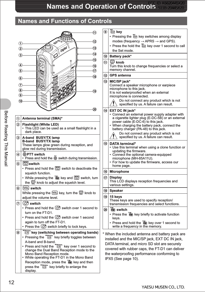
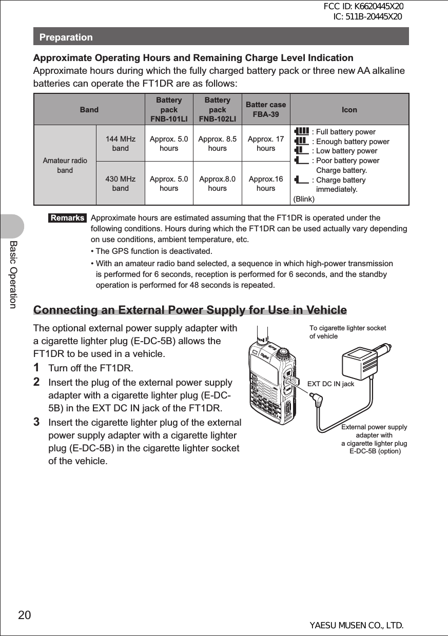
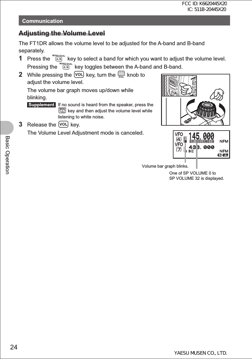
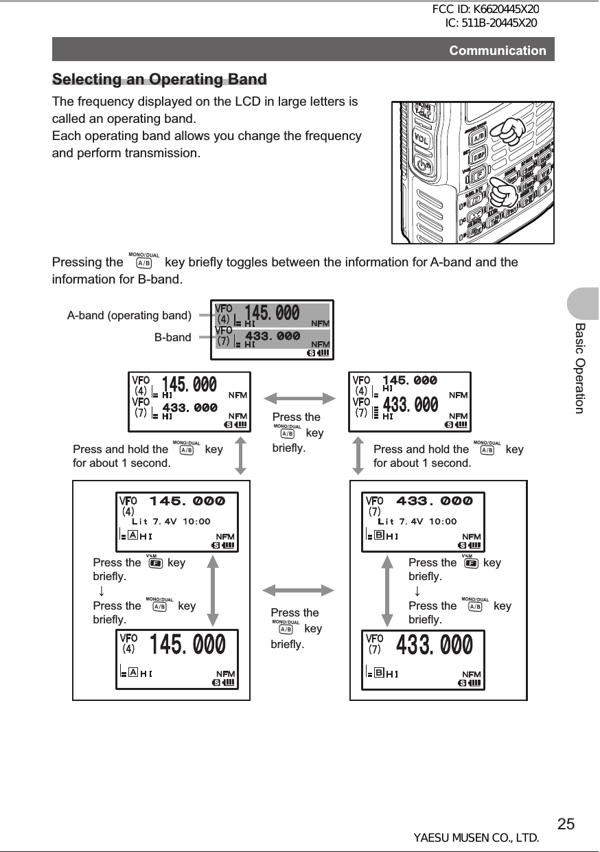
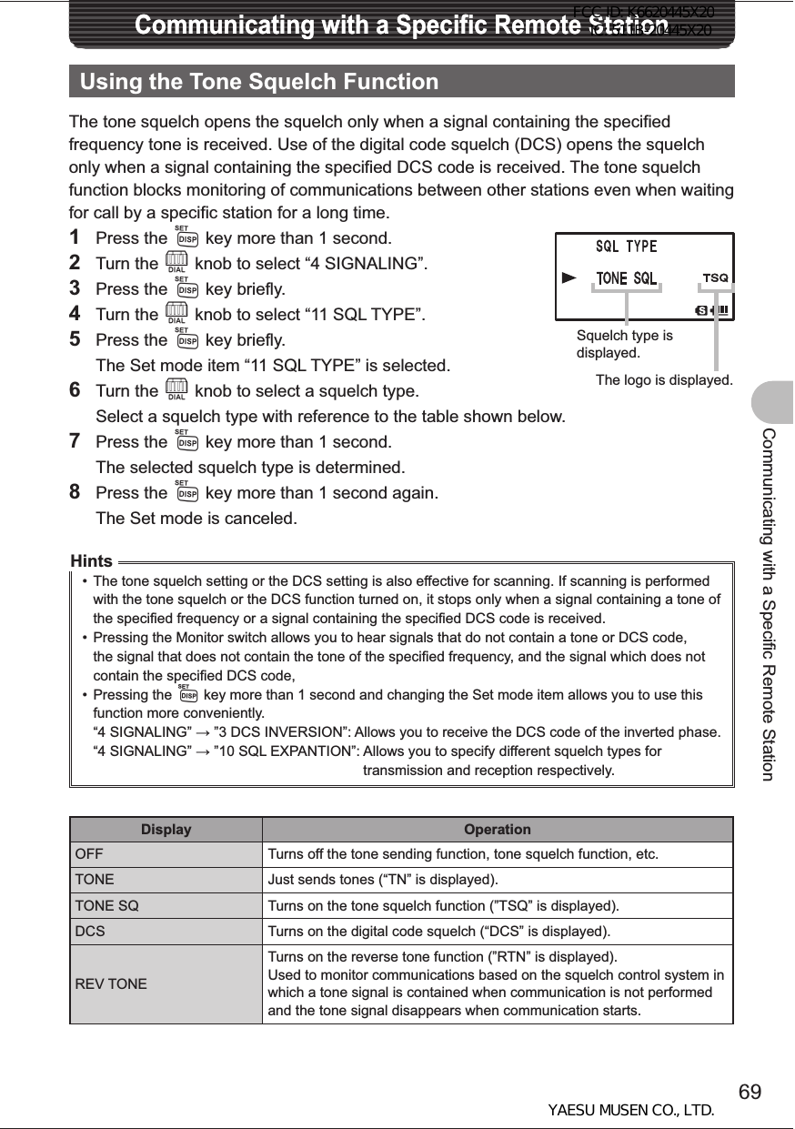
![14Before Reading This ManualNames and Functions of Controls 䰢䰒䰛䰚䰒䰙䰚䰒䰙䰔䰕䰔 䰕䰔䰕䰔 䰕䯴䰀䯵䰢䰒䰛 䰀䯿䯿䯺䯼䯼䯼䯽䰀䰁䯺䯼䯼䯼䯴䰃䯵䰀䯴䰃䯵aabc de fbcd e f ghighiA-band display areaB-band display areaIcon display areaaDisplays choice of the VFO mode or MR (memory) mode.bDisplays a sound volume bar graph.cDisplays a transmission power level icon.dDisplays an operating frequency.eS meter: Displays the radio wave strength in 9 steps.PO meter: Displays the transmission power level in 4 steps.H I: High power (5 W) L 3: LOW 3 power (2.5 W) L 2: LOW 2 power (1 W) L 1: LOW 1 power (0.05 W) fDisplays the operating mode (radio wave type).gDisplays a squelch type (See page 136). TN: Stays lit when the tone encoder function is active.TSQ: Stays lit when the tone squelch function is active.DCS: Stays lit when the DCS function is active.RTN: Stays lit when the reverse tone function is active.PAG: Stays lit when the pager is active.MSG: Stays on when the message function is active.Displays the APRS baud rate (See page 71).hDisplays a shift direction during repeater operation. (See page 30) -Minus shift +Plus shift @Split operationb is displayed when the bell alarm function is active (See page 140).iDisplayed when the vibrator function is active.Solid line (): BUSY vibrator function (See page 139)Dashed line: SIGNALING vibrator function (See page 139)Short dashed line (----): APRS MSG vibrator function (See page 96)IconsIcon DescriptionfLights when a function key is pressed.iStays lit during internet communication such as WiRES (See page 31). dStays lit when the DTMF function is active (See page 36, 130). [Stays lit when the APO function is active (See page 150). lStays lit when the LOCK function is active (See page 29). ]Stays lit when the MUTE function is active (See page 27). sStays lit when a micro SD memory card is inserted.Icon DescriptionH IDisplays the transmission power level (See page 27).H I: High power (5W)L 3: LOW 3 power (2.5W)L 2: LOW 2 power (1W)L 1: LOW 1 power (0.05W)<Displays the battery charge level.< : Enough battery power> : Low battery power? : Poor battery power._ : Charge battery._ : Charge battery immediately (blink).FCC ID: K6620445X20 IC: 511B-20445X20YAESU MUSEN CO., LTD.](https://usermanual.wiki/Yaesu-Musen/20445X20.USERS-MANUAL/User-Guide-1754613-Page-14.png)
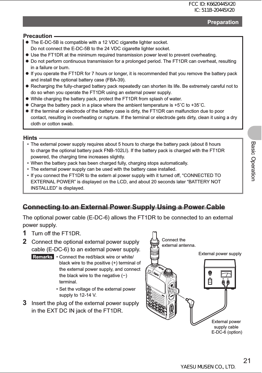
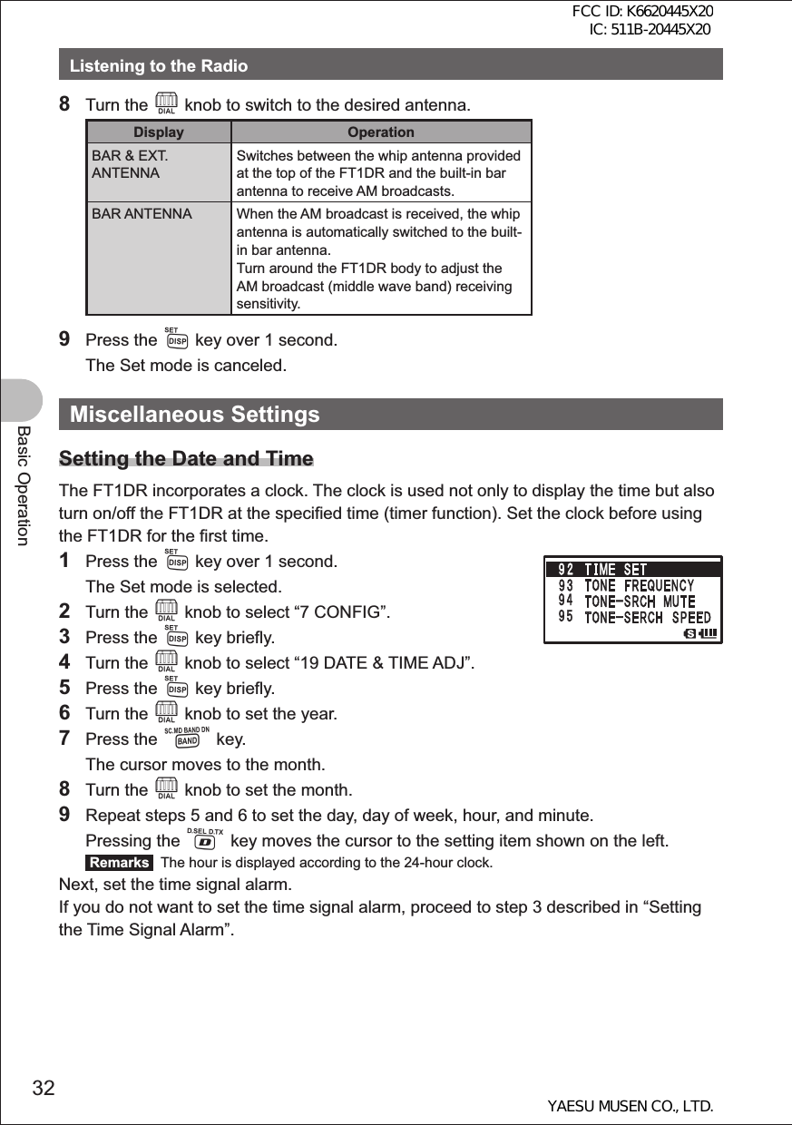
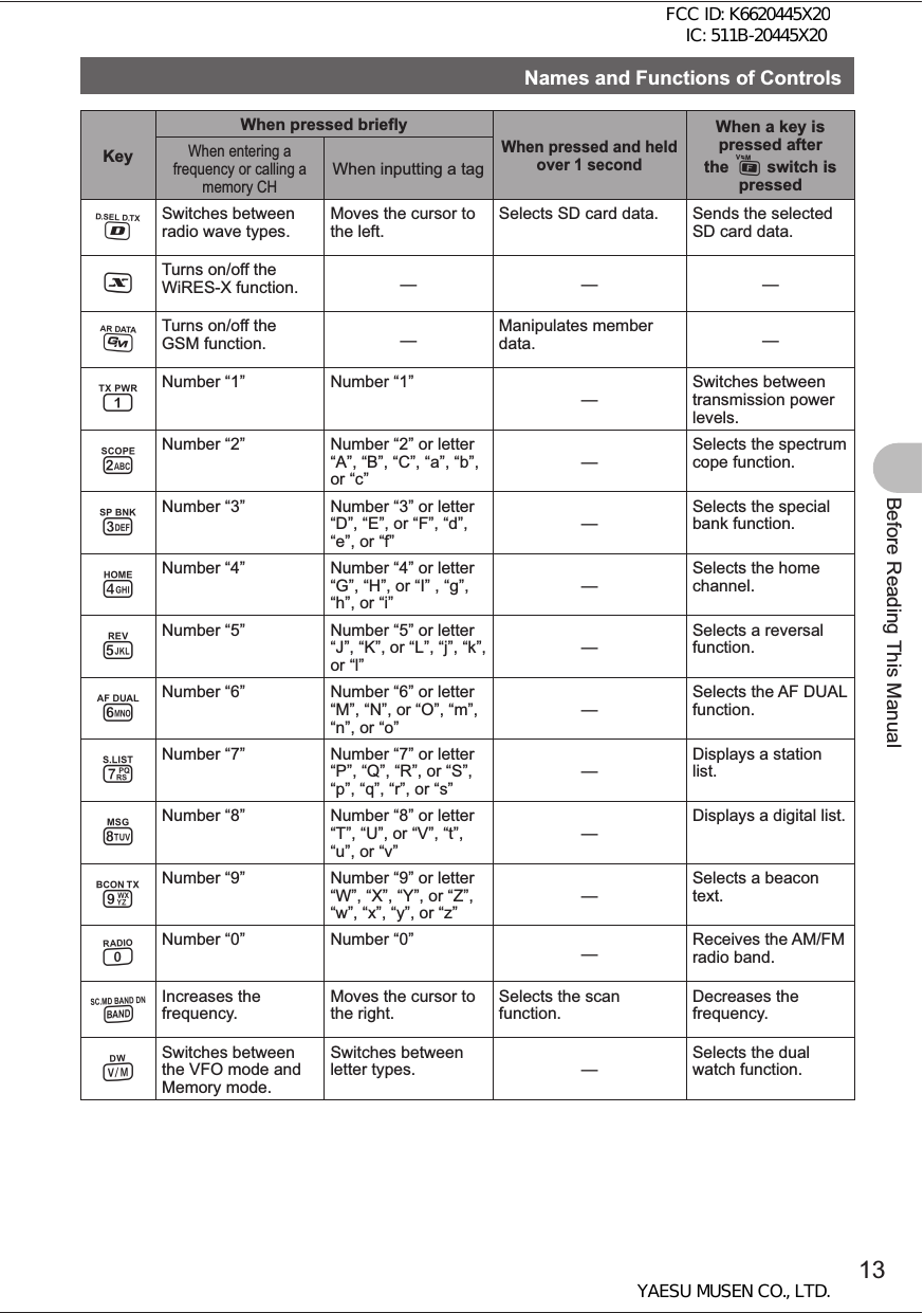
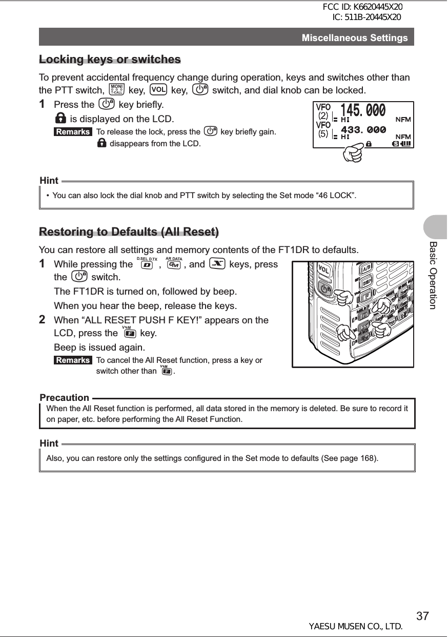
![34Basic OperationMiscellaneous Settings4 Turn the O knob to select “3 AUDIO”.5 Press the M key briefly.6 Turn the O knob to select “2 MUTE”.7 Press the M key briefly.8 Turn the O knob to select a muting level. Remarks You can select one of the following four muting levels: • MUTE 30% • MUTE 50% • MUTE 100% • OFF The larger the value, the smaller the sound. To deactivate the muting function, select OFF.9 Press the M key over 1 second.10 Press theM key over 1 second again. The Set mode is canceled. Remarks When the muting function is activated, the ] icon is displayed on the LCD. When the muting function is being performed (sound is being muted actually), the ] icon blinks on the LCD.Hint• When no signal is received on the operating band even if the muting function is activated, sound is not muted.Changing the Transmission Power LevelThe maximum transmission power of the FT1DR is 5 W. When communicating with a friend in the immediate area or you want to suppress battery power consumption, you can lower the transmission power. For power supply types and transmission power levels, see the table shown below.1 Press the F key briefly, and the press the 1 key briefly. f is displayed on the LCD. Select your desired transmission power level while f is displayed. The icon and PO meter which correspond to the selected transmission power level appear. The current power level is displayed, for about 2 seconds, in the area where a frequency is displayed. Example: HIGH POWERBattery typeH (High power)L3 L2 L1Battery pack5W 2.5W 1W 0.05WExternal power supply (13.8 VDC)Battery case (alkaline batteries) 1W 0.05WFCC ID: K6620445X20 IC: 511B-20445X20YAESU MUSEN CO., LTD.](https://usermanual.wiki/Yaesu-Musen/20445X20.USERS-MANUAL/User-Guide-1754613-Page-34.png)
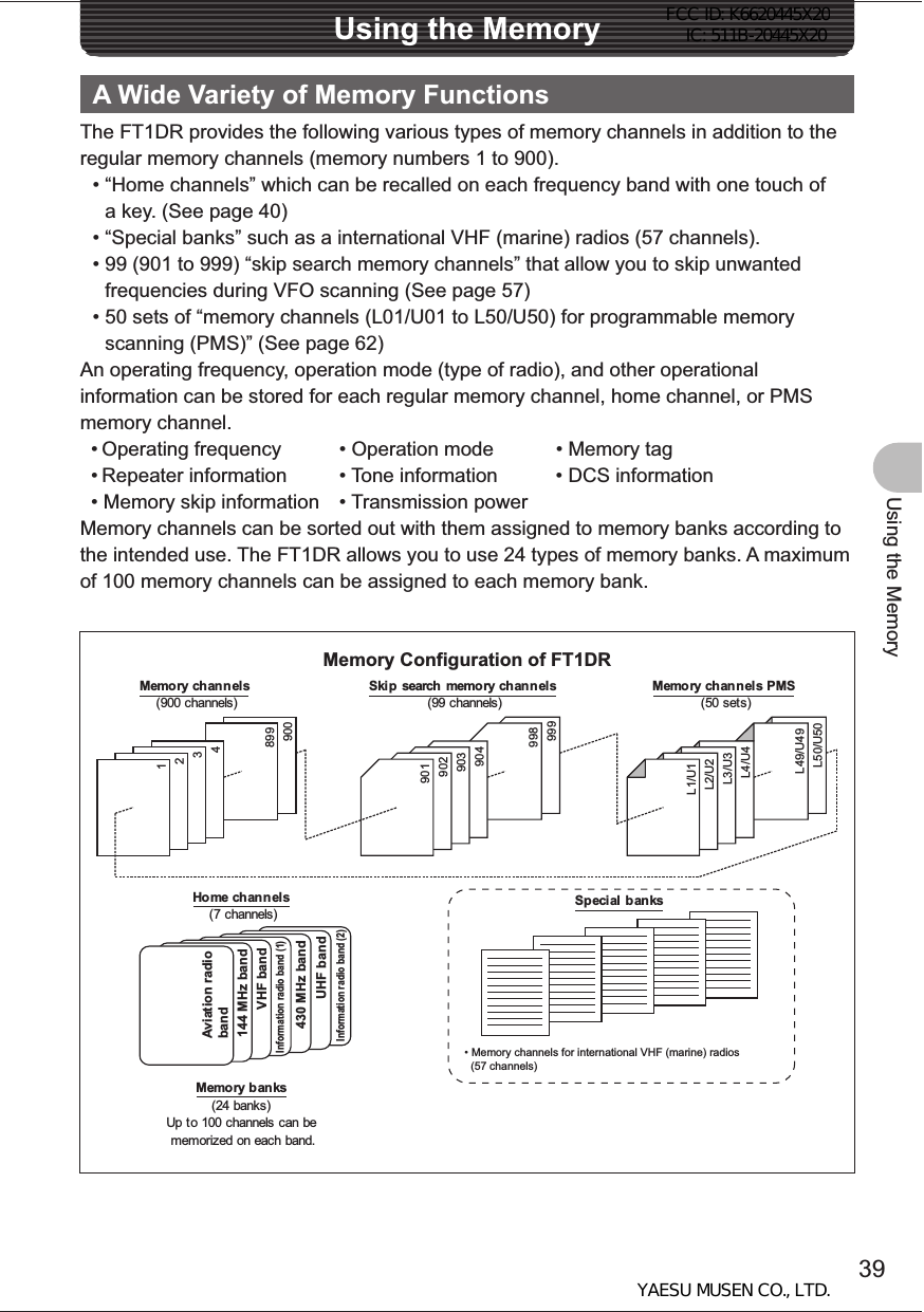
![40Using the MemoryA Wide Variety of Memory FunctionsWriting into the MemoryPrecautionThe stored data can be erased due to wrong operation, static electricity, or electrical noise. Also, it can be erased in the case of a failure or repair. Be sure to write it down on paper or the like.The FT1DR allows you to use 900 channels (memory channel numbers 1 to 900).1 Select the VFO mode.2 Turn the O knob to select a frequency. Select the frequency you want to write into the memory.3 Press the F key more than 1 second. The Memory Write mode is selected, and the number of the memory channel next to the memory channel for which you stored a frequency last blinks. Remarks • To cancel the memory write operation, press the p switch. • To store a frequency with a memory channel specified, turn the O knob to select the memory channel [The specified channel is unregistered] ( icon is displayed, and the memory channel blinks. [The specified channel is registered] ) icon is displayed, and “OVERWRITE OK?” is displayed on the LCD. • Pressing the M key allows you to skip channels quickly in steps of 100 channels.4 Press the F key briefly. The memory write operation is completed, and the registered frequency is displayed on the LCD.Hints• By default, 145.000MHz was registered to memory channel 1. It can be changed to another frequency, but cannot be deleted.• The frequency which has previously been registered to a memory channel can be overwritten with a new frequency. When you intend to write a new frequency into the memory, an unregistered memory channel is displayed.• To display the lowest unregistered memory number when you start writing into the memory, press the M key more than 1 second to select the Set mode, and then select “3 MEMORY” “6 MEMORY WRITE”. • To inhibit writing into all memories, press the M key more than 1 second, and then select “3 MEMORY” “4 MEMORY PROTECT”.FCC ID: K6620445X20 IC: 511B-20445X20YAESU MUSEN CO., LTD.](https://usermanual.wiki/Yaesu-Musen/20445X20.USERS-MANUAL/User-Guide-1754613-Page-40.png)
![42Using the MemoryA Wide Variety of Memory FunctionsRecalling the Home Channel1 Press the F key briefly. The home channel of the currently selected frequency band is displayed on the LCD. Hints • For the relationship between the frequency bands and the home channel frequencies, see the table on the next page. • Selecting a frequency by turning the O key allows you to return to the VFO mode.Returning to the Previous Frequency1 Press the F key briefly. The frequency used before recalling the home channel is displayed on the LCD.Frequency band Frequency Frequency band FrequencyShortwave band [1] 1.800 MHz Information radio (1) [6] 380.000 MHz50 MHz [2] 51.000 MHz 430 MHz band [7] 433.000 MHzAviation radio [3] 108.000 MHz470 to 770 MHz band [8]481.750 MHz144 MHz band [4] 145.000 MHz Information radio (2) [9] 860.000 MHz174 to 222 MHz band [5] 175.750 MHz OChanging a Home Channel FrequencyYou can change a default home channel frequency.1 Select the VFO mode.2 Turn the O knob to select a frequency. Select a frequency to change.3 Press the F key more than 1 second. The Write mode is selected.4 Press the X key briefly. “OVERWRITE OK?” is displayed on the LCD for about 5 seconds.5 Press the X key briefly. When the new frequency has been written, the home channel frequency of the selected frequency band is changed.Deleting the Memory Channel1 Select the Memory mode.2 Press the F key more than 1 second.3 Turn the O key to select the memory channel to delete.4 Press the D key briefly. “CLRAR OK?” is displayed on the LCD for about 3 seconds. Remarks Pressing the F key allows you to cancel the memory channel deletion operation.FCC ID: K6620445X20 IC: 511B-20445X20YAESU MUSEN CO., LTD.](https://usermanual.wiki/Yaesu-Musen/20445X20.USERS-MANUAL/User-Guide-1754613-Page-42.png)
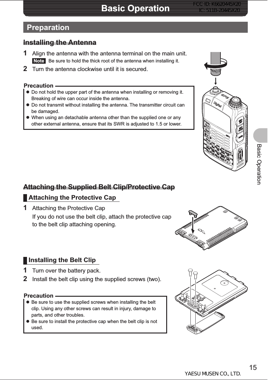
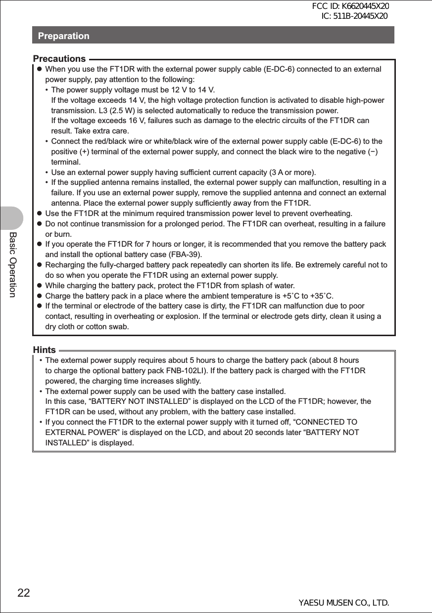
![43Using the MemoryA Wide Variety of Memory Functions5 Press the D key briefly. The memory channel is deleted. Remarks To delete other memory channels, repeat steps 2-5.Precaution zMemory channel 1 cannot be deleted.HintThe memory channel specified as a priority memory channel cannot be deleted. Before deleting it, specify another memory channel as a priority memory.Restoring the Deleted Memory ChannelYou can restore a deleted memory channel.1 Select the Memory mode. The memory channel used last is displayed.2 Press the F key more than 1 second.3 Turn the O knob to select the memory channel to restore.4 Press the D key briefly. The deleted memory channel is restored.Using Memory BanksRegistered memory channels can be sorted out according to the intended use. The FT1DR allows you to use 24 types of banks. A maximum of 100 memory channels can be assigned to each memory bank.One memory channel can be registered in two or more memory banks. If the memory channel registered in the memory bank is changed or updated, the content of the corresponding memory channel in the memory bank is automatically changed or updated. EEEEEEEEEaaaaaaaaaE aE aa 0+] 0+] 0+] 0+] 0+] 0+] aMemory channel Memory bank144MHz band is registered.430MHz band is registered.Amateur bands are registered together.AIR band is registered.FCC ID: K6620445X20 IC: 511B-20445X20YAESU MUSEN CO., LTD.](https://usermanual.wiki/Yaesu-Musen/20445X20.USERS-MANUAL/User-Guide-1754613-Page-43.png)
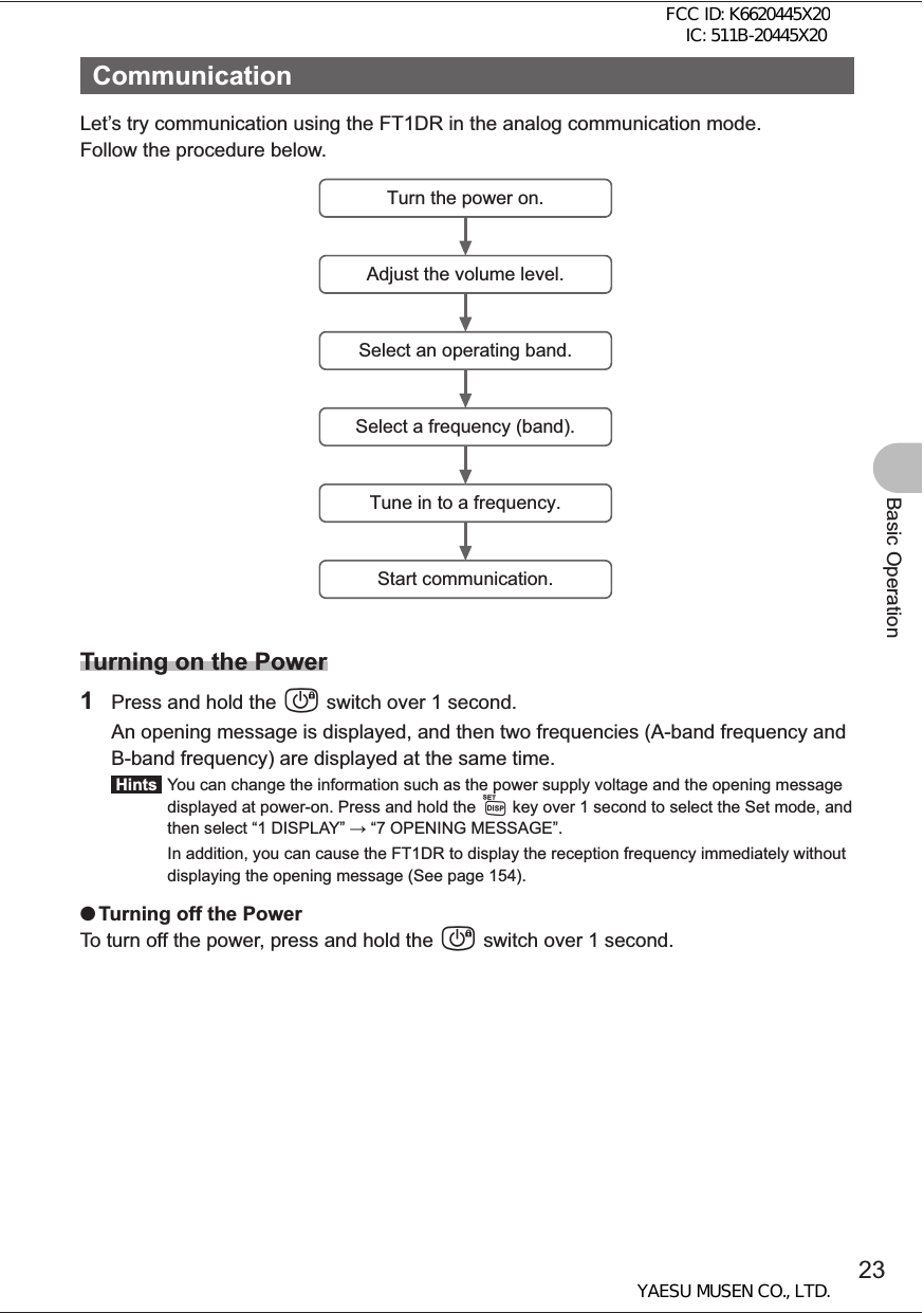
![53Scanning FunctionUsing the Scanning FunctionSpecifying a Skip/Selected Memory ChannelYou can specify two types of memory channels, a skip memory channel and a selected memory channel, for effective memory scanning.Skip memory channel: You can specify a memory channel that need not be scanned during memory scanning.Selected memory channel: You can specify selected memory channels so that only the specific memory channels are scanned during memory scanning.1 Select the Memory mode, and then recall the memory channel you want to specify as a skip memory channel or a selected memory channel. 2 Press the M key more than 1 second. The Set mode is selected.3 Turn the O knob to select “3 MEMORY”.4 Press the M key briefly.5 Turn the O knob to select “5 MEMORY SKIP”.6 Press the M key briefly.7 Turn the O knob to select “OFF”, “SKIP”, or “SELECT”.8 Press the M key more than 1 second.9 Press the M key more than 1 second again. The Set mode is canceled. Hints To cancel a skip/selected memory channel, select [OFF]. When it is canceled, the icon on the LCD disappears.Skip memory channel [SKP]Selected memory channel [SELECT]O[OFF]Stays lit for the skip memory.Blinks for the selected memory channel.FCC ID: K6620445X20 IC: 511B-20445X20YAESU MUSEN CO., LTD.](https://usermanual.wiki/Yaesu-Musen/20445X20.USERS-MANUAL/User-Guide-1754613-Page-53.png)

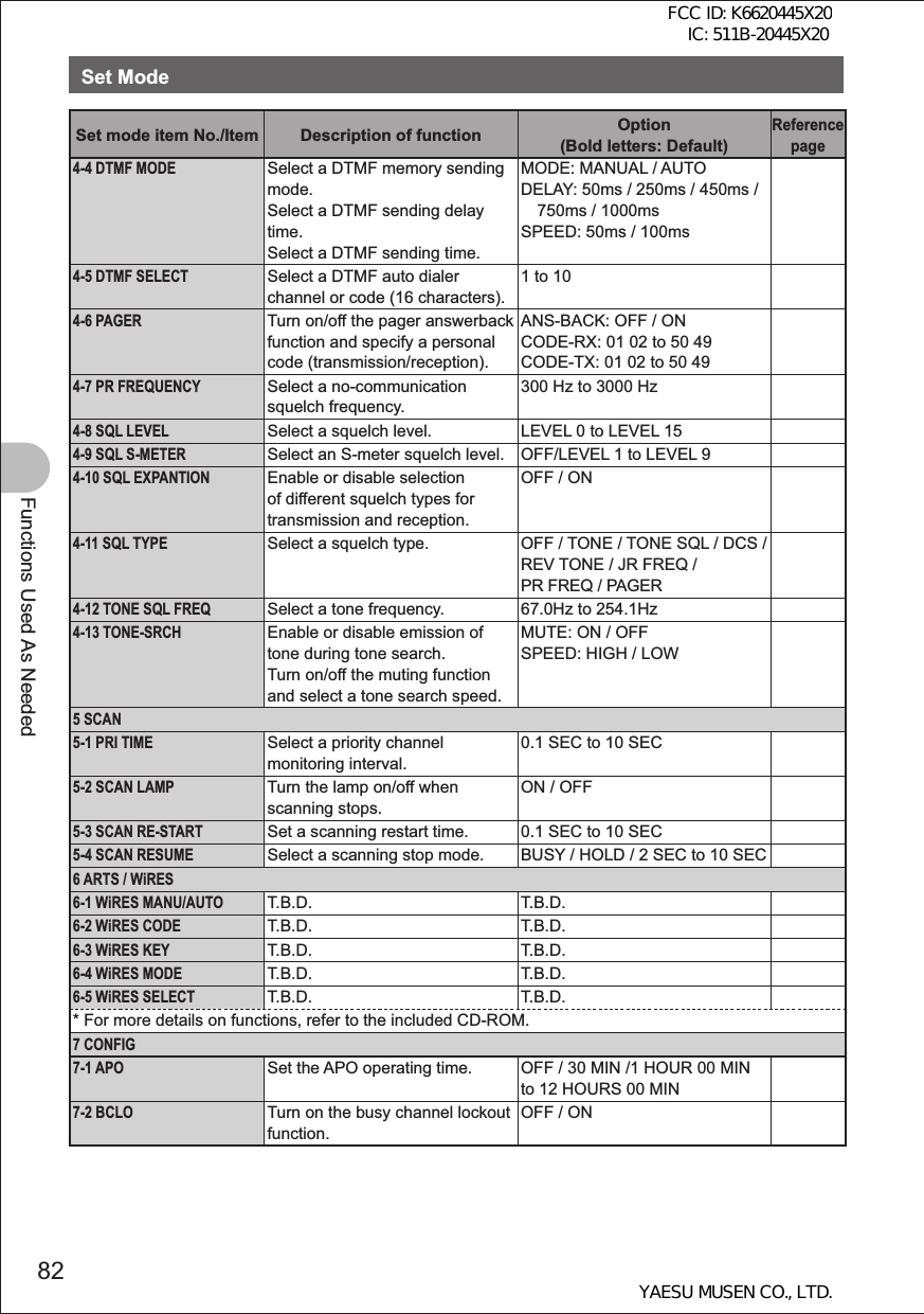
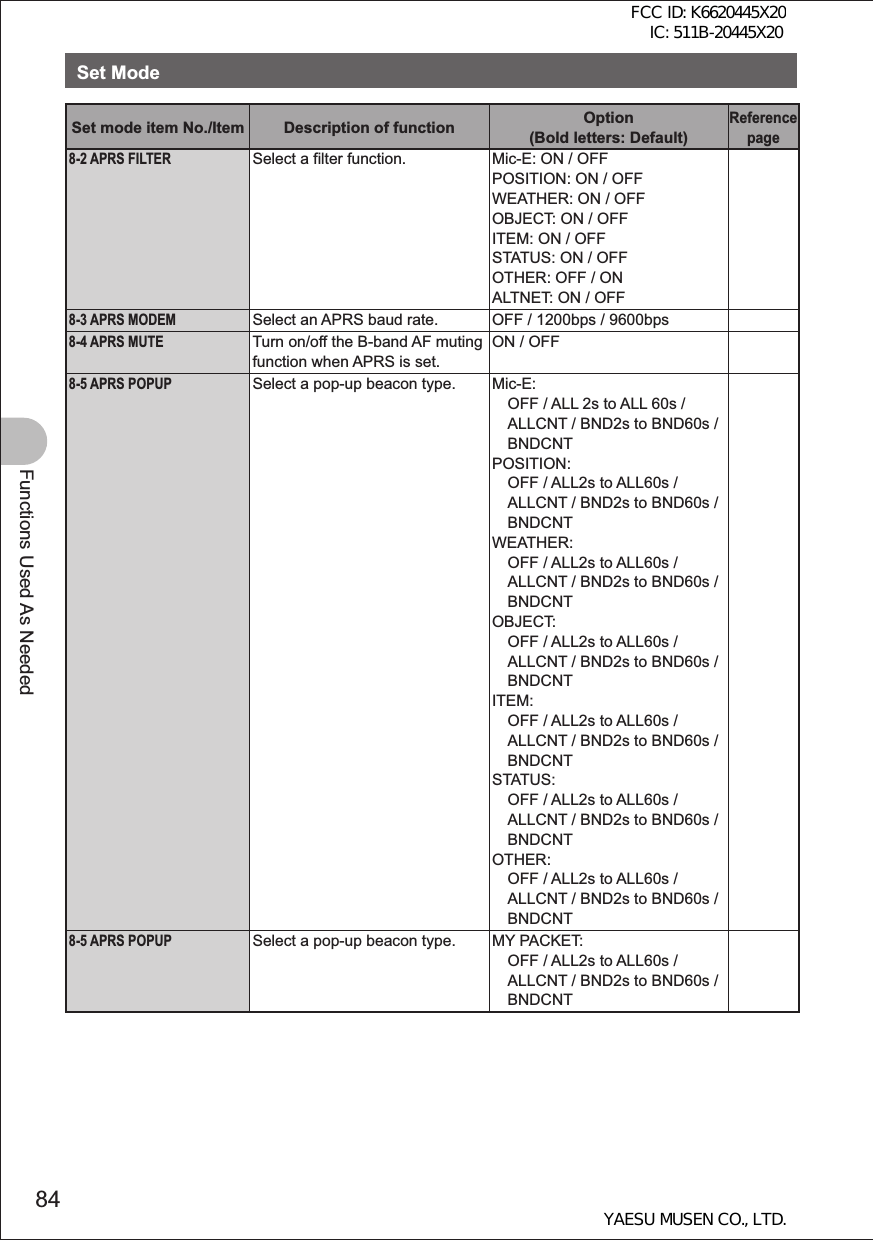
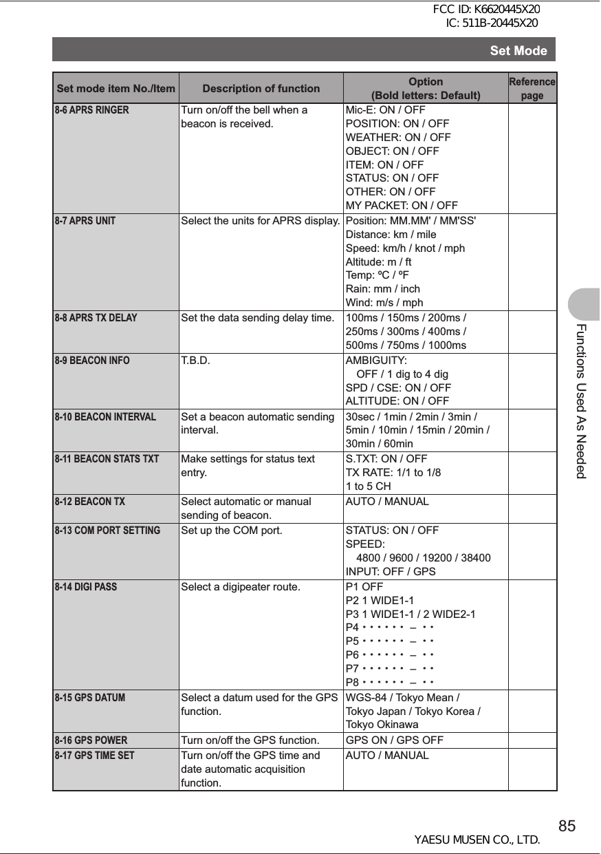
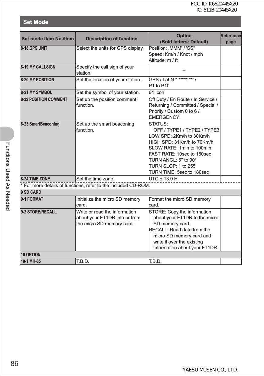
![83Functions Used As NeededSet ModeSet mode item No./Item Description of function Option (Bold letters: Default)Reference page7-3 BEEPSet up the beep output function and the function of emitting a beep when a band edge/CH1 is encountered.SELECT: KEY&SCAN / KEY / OFFEDGE: OFF / ON7-4 BUSY LEDTurn on/off the BUSY LED A BAND: ON / OFFB BAND: ON / OFFRADIO: ON / OFF7-5 CLOCK TYPESelect a clock type. A / B7-6 GPS LOGSet the duration of GPS access. OFF / 1 SEC / 2 SEC / 5 SEC / 10 SEC / 30 SEC / 60 SEC7-7 HOME VFOEnable/disable VFO transfer via the home channel.ENABLE / DISABLE7-8 LED LIGHTTurn on/off the white LED flashlight.WHITE LED ON7-9 LOCKSelect a lock mode. KEY&DIAL / PTT / KEY&PTT / DIAL&PTT / ALL / KEY / DIAL7-10 MONI/T-CALLSelect a monitor switch or T-CALL switch.MONI / T-CALL7-11 TIMERSet the power ON/OFF timer. ON: 00:00 to 23:59 ON / OFFOFF: 00:00 to 23:59 ON / OFF7-12 PASSWORDTurn on/off the password function.ON / OFF [ – – – – ]7-13 PTT DELAYSet the PTT delay time. OFF / 20ms / 50ms / 100ms / 200ms7-14 RPT ARSTurn on/off the ARS function. ON / OFF7-15 RPT SHIFTSelect a repeater shift direction. SIMPLEX / –RPT / +RPT7-16 RPT SHIFT FREQSelect a repeater shift width. 0.000 MHz to 150.000 MHz7-17 SAVE RXSet the reception save time. OFF / 0.2 SEC (1:1) to 60.0 SEC (1:300)7-18 STEPSelect a channel step. AUTO / 5.0KHZ to 100KHz7-19 DATE & TIME ADJSet up the built-in clock function. –7-20 TOTSet the timeout timer. OFF / 30 SEC to 10 MIN 00 SEC7-21 VFO MODESelect the frequency selection range in the VFO mode. ALL / BAND7-22 VIBRATORSelect a vibrator mode and set up the vibrator function.MODE: OFF / BUSY / SIGNALINGSELECT: MODE1 / MODE2 / MODE38 APRS8-1 APRS AF DUALTurn on/off the muting function when both the APRS function and AF dual function are active. ON / OFFFCC ID: K6620445X20 IC: 511B-20445X20YAESU MUSEN CO., LTD.](https://usermanual.wiki/Yaesu-Musen/20445X20.USERS-MANUAL/User-Guide-1754613-Page-83.png)