Yaesu Musen 20345X40 AMATEUR RADIO WITH SCANNING RECEIVER User Manual OM
Yaesu Musen Co., Ltd. AMATEUR RADIO WITH SCANNING RECEIVER OM
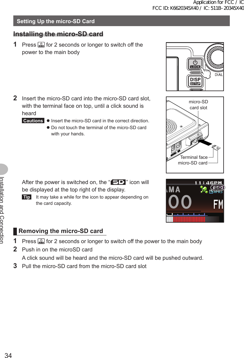
Contents
- 1. User Manual
- 2. User Manual 1
- 3. User Manual 2
- 4. User Manual 3
- 5. User Manual 4
- 6. User Manual 5
- 7. User Manual 6
- 8. User Manual 7
- 9. User Manual 8
- 10. User Manual 9
- 11. User Manual 10
- 12. User Manual 11
- 13. User Manual 12
- 14. User Manual 13
- 15. User Manual 14
- 16. User Manual 15
- 17. User Manual 16
- 18. User Manual 17
- 19. User Manual 18
- 20. User Manual 19
- 21. User Manual 20
- 22. User Manual 21
User Manual 3
![29Installation and ConnectionConnectingtheRadioConnectingthecontrollertothemainbodyCautionMake sure the power supply is switched OFF before connecting the cable between the controller and the main body.1 Plug the connector of the controller cable into the [CONTROL] jack at the front of the main body until a click sound is heard本体コントロールケーブルMain bodyController cable2 Plug the other connector of the controller cable into the [CONTROL] jack at the back of the controller until a click sound is heardコントロールケーブルコントローラControllerController cableConnectingthemicrophone1 Plug the microphone connector into the [MIC] jack at the front of the main body until a click sound is heardTips • To remove the microphone, pull the connector out while pressing the latch. • Using the optional microphone extension kit “MEK-2”, a microphone with a 8-pin connector can be used. A microphone extension cable (about 3 m long) is also included in MEK-2. Use it to install the microphone in locations which cannot be reached by the attached microphone cable.LOCKP3P2P171482059BACD36P4LAMPDTMF MICROPHONEMH-48ABCJKLTUVGHIPQRSDEFMNOWXYZMICコネクタマイクロホンMicrophoneConnectorConnectingtheantenna1 Attach the antenna co-axial cable to the [ANT] terminal at the back of the main body and tighten the connector同軸ケーブル端子本体(後面)Main body (rear side)Co-axial cable connectorApplication for FCC / IC FCC ID: K6620345X40 / IC: 511B-20345X40](https://usermanual.wiki/Yaesu-Musen/20345X40.User-Manual-3/User-Guide-2766130-Page-1.png)
![35Installation and ConnectionSettingUpthemicro-SDCardInitializingthemicro-SDcardWhen using a new micro-SD card, initialize the micro-SD card according to the following procedure.CautionUpon initialization, all the data recorded in the micro-SD card will be erased. Check the contents of the micro-SD card before initialization.1 Press for one second or longer The set-up menu will be displayed.2 Touch [SDCARD] The menu list will be displayed.$#%-$#%-6:4:5'672/'074'5'6%.10'%10(+)9Ჰ4'55%#0&+52.#;5+) 0#.+0)#245 126+105&%#4&/'/14;&#6#%#..5+) 03 Touch [3FORMAT] The format confirmation screen will be displayed.5&%#4&(14/#6)4172+&$#%-72ᲹᲺ$#%-$#%-4 Touch [OK?] The micro-SD card will be initialized.Tip Touch [Cancel] to stop the initialization. “Completed” will be displayed when initialization is completed and the screen will then return to the menu list.5&%#4&(14/#6)4172+&$#%-72ᲹᲺ$#%-$#%-%CPEGᲴ1-!(14/#6Application for FCC / IC FCC ID: K6620345X40 / IC: 511B-20345X40](https://usermanual.wiki/Yaesu-Musen/20345X40.User-Manual-3/User-Guide-2766130-Page-7.png)
![37Basic OperationsReceivingInputingthecallsignWhen switching the power on for the first time after purchasing, or after resetting the device, a screen requesting the call sign of your own station be entered will be displayed.The call sign is used to identify the transmitting station when communicating in the digital mode.1 Touch the blinking [CALLSIGN]Tips The display will change to the character input screen automatically if there are no operations for about 3 seconds.%#..5+)02ᲴGCUGGPVGT/CZᲹᲸᲴGVVGTU;QWT%CᲴ ᲴUKIP2 Touch a character key The touched character will be displayed at the top of the screen. Enter each character of your call sign.Tips • Up to 10 characters (letters, numbers, and a hyphen ) can be entered. • Refer to Page 23 on how to operate the character input screen.39'46; 7 +12#5&()*,- .<:%8$0/#$% 5RCEG'06@ᲹᲺ%CRU$#%-3 Touch [ENT] The screen will change. Thereafter, the entered call sign is displayed at the bottom of the power on screen, and the display will switch to the frequency display screen (dual band screen).ᲹᲺᲽᲾᲿ᳀ ᳁ ᳂ " #$% 5RCEG'06%CPEGᲴ!@ᲹᲺ2%ᲹᲹ Ჺ;*,2%ᲹᲹ Ჺ;*,Application for FCC / IC FCC ID: K6620345X40 / IC: 511B-20345X40](https://usermanual.wiki/Yaesu-Musen/20345X40.User-Manual-3/User-Guide-2766130-Page-9.png)
![39Basic OperationsReceivingAdjustingthesquelchlevelAnnoying noises can be muted when a signal cannot be detected. Band A and Band B squelch levels can be individually adjusted. Noise can be canceled more easily when the squelch level is increased but it may become more difficult to pick up weak signals. Adjust the squelch level as required.1 Touch [SQL] When [SQL] turns orange, the VOL meter below the frequency will change to show the SQL level setting.ᲹᲽᲸᲸᲸ ᲸᲸᲸ/76'5%12'/853.8(18(1ᲹᲽᲸᲸᲸ ᲸᲸᲸ/76'5%12'/853.8(18(12 Turn to adjust the squelch level The level will be displayed in the SQL meter.Tip The SQL meter will return to the VOL meter if there is no operation for three seconds.ᲹᲽᲸᲸᲸ ᲸᲸᲸ/76'5%12'/853.8(18(1Application for FCC / IC FCC ID: K6620345X40 / IC: 511B-20345X40](https://usermanual.wiki/Yaesu-Musen/20345X40.User-Manual-3/User-Guide-2766130-Page-11.png)
![40Basic OperationsReceivingTuningtheradio ●Usingtheknobs1 Turn The frequency will increase when the knob is turned in a clockwise direction and decrease when turned in a counter-clockwise direction. ●Usingthemicrophonekeys1 Press [UP] or [DWN] The frequency increases when [UP] is pressed, and decreases when [DWN] is pressed.UPDWN ●Enteringthenumericalfigures1 Press The function menu will be displayed.2 Touch [] The number input screen will be displayed.ᲹᲽᲾᲸᲸᲹᲺ᳀;1-1*#/# ᳀ᲾᲸ/76'5%12'/853.8(15-+25'.1((&96Z294*+5%#0 4'8(9&$#%-Application for FCC / IC FCC ID: K6620345X40 / IC: 511B-20345X40](https://usermanual.wiki/Yaesu-Musen/20345X40.User-Manual-3/User-Guide-2766130-Page-12.png)
![41Basic OperationsReceiving3 Touch a number key The touched number will be displayed at the top of the screen.Tip Refer to Page 23 for operation of the number input screen.ᲹᲺᲽᲾᲿ᳀᳁᳂#$%&5RCEG'06 ᳀ᲾᲸ$#%-4 Touch [ENT] The display will return to the function menu and the entered frequency of the operating band will be displayed at the top of the screen.ᲹᲺᲽᲾᲿ᳀᳁᳂#$%&5RCEG'06ᲹᲽ ᲾᲺᲸ$#%-ᲹᲽᲾᲸᲸᲹᲺ᳀;1-1*#/#ᲹᲽ ᲾᲺᲸ/76'5%12'/853.8(15-+25'.1((&96Z294*+5%#0 4'8(9&$#%-ChangingthefrequencystepsThe frequency step while tuning with the knob or [UP]/[DWN] keys of the microphone, can be changed. ●Changingthefrequencystepto1MHztemporarily1 Press of the operating band, or touch the frequency display area of the operating band The MHZ field in the frequency display will blink.ᲹᲽᲾᲸᲸ8(1 ᳀ᲾᲸᲽᲸᲸ61-;1Ჺ/76'5%12'/853.Application for FCC / IC FCC ID: K6620345X40 / IC: 511B-20345X40](https://usermanual.wiki/Yaesu-Musen/20345X40.User-Manual-3/User-Guide-2766130-Page-13.png)
![43Basic OperationsReceiving2 Turn The frequency will change in steps of 5 MHz.Tip When there is no operation for three seconds, the kHz digits will be displayed and the frequency step will return to the normal step.ᲹᲸ8(1 ᳀ᲾᲸᲽᲸᲸ61-;1Ჺ/76'5%12'/853. ●Changingthefrequencystepusingtheset-upmenu1 Press for one second or longer The set-up menu will be displayed.2 Touch [CONFIG] The menu list will be displayed.$#%-$#%-6:4:5'672/'074'5'6%.10'%10(+)9Ჰ4'55%#0&+52.#;5+) 0#.+0)#245 126+105&%#4&/'/14;&#6#%#..5+) 03 Turn or touch the screen to select [7FMAMSTEP]Application for FCC / IC FCC ID: K6620345X40 / IC: 511B-20345X40](https://usermanual.wiki/Yaesu-Musen/20345X40.User-Manual-3/User-Guide-2766130-Page-15.png)
![44Basic OperationsReceiving4 Touch [7FMAMSTEP] The frequency step that is currently set up will change to orange.$#%-$#%-%10(+)4265*+(6(4'3(/#/56'2$''2 /*\.19#7611((4265*+(6$#%-$#%-4265*+(6(4'3(/#/56'2$''2 /*\.19#7615 Turn to select the frequency step The setting will change in the following sequence: AUTO → 5.00 KHz → 6.25 KHz → 8.33 KHz (air band only) → 10.00 KHz → 12.50 KHz → 15.00 KHz → 20.00 KHz → 25.00 KHz → 50.00 KHz → 100.00 KHzTip Factory default value: AUTO6 Touch [7FMAMSTEP] The selected frequency step will be set, changing from orange to green.$#%-$#%-4265*+(6(4'3(/#/56'2$''2 /*\ -*\.19$#%-$#%-4265*+(6(4'3(/#/56'2$''2 /*\ -*\.197 Press for one second or longer The frequency step will be set and the display will return to the previous screen.Tip The display can also be returned to the previous screen by touching [BACK] twice.SwitchingtheoperatingmodeThe operating mode can be switched between the VFO mode where the frequency can be freely set, and the memory mode where the channels saved in the memory are recalled for operation.1 Choose the operating bandApplication for FCC / IC FCC ID: K6620345X40 / IC: 511B-20345X40](https://usermanual.wiki/Yaesu-Musen/20345X40.User-Manual-3/User-Guide-2766130-Page-16.png)