Yaesu Musen 20321X70 LINEAR AMPLIFIER User Manual
Yaesu Musen Co., Ltd. LINEAR AMPLIFIER Users Manual
UserManual.wiki
>
Yaesu Musen
>
20321X70 User Manual
Users Manual
Navigation menu
Upload a User Manual
Namespaces
Wiki Guide
HTML
PDF
Info
Views
User Manual
Discussion / Help
Navigation
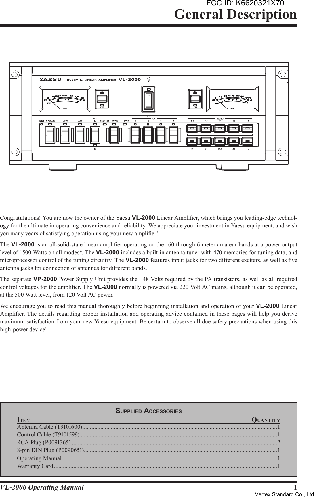
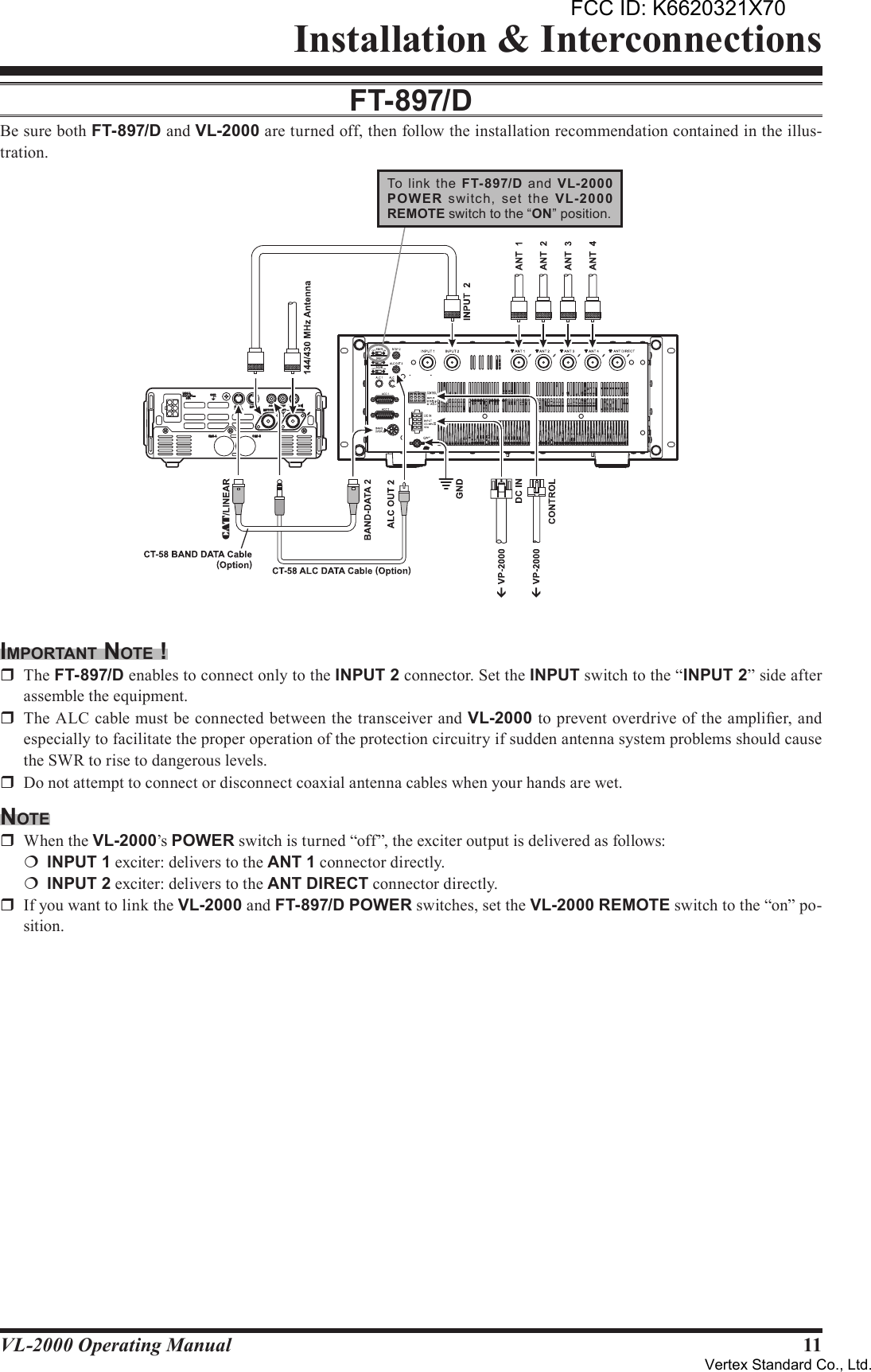
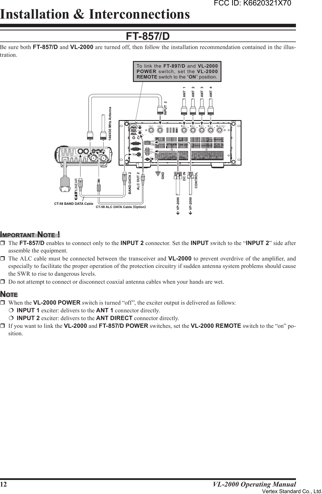
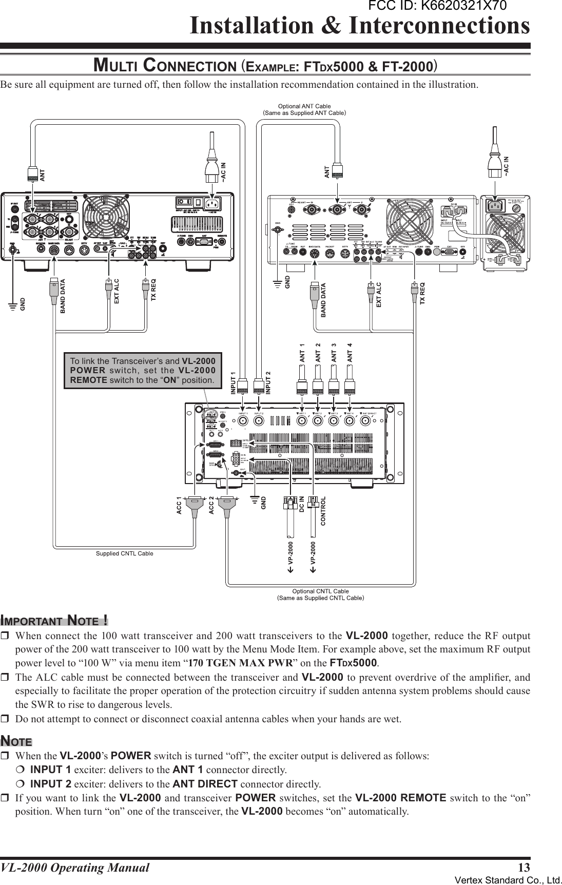
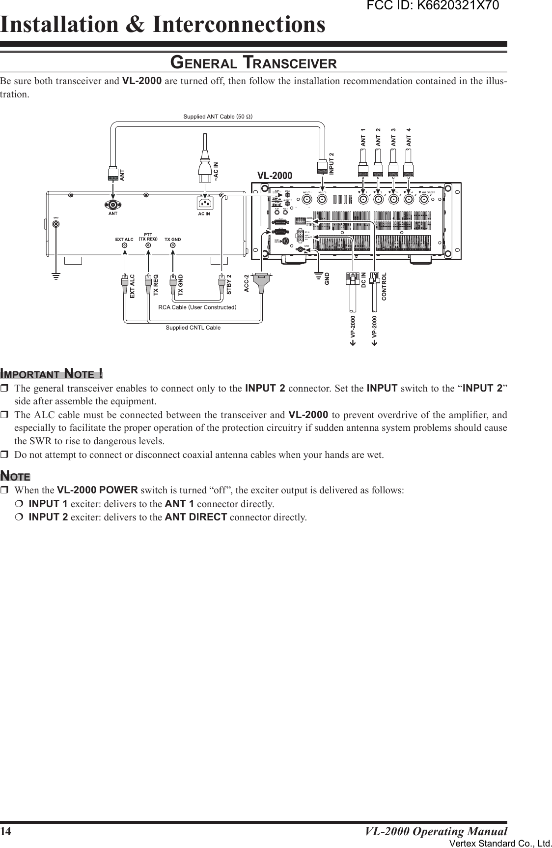
![2VL-2000 Operating ManualFront Panel Controls & SwitchesPOWER Switch This switch turns the VL-2000 “on” and “off”. When the VP-2000 [POWER] switch is set to the “off” position, this switch will not function. If using the Yaesu transceiver with a BAND DATA Cable, the VP-2000 AC power will be remotely con-trolled by the transceiver’s power switch when the REMOTE switch on the rear panel of the VL-2000 is set to “on”. Caution: Never turn “off” this switch while transmit-ting.METER-1 Switch Press this switch to toggle the METER-1 function be-tween “PO” meter and “SWR” meter.METER-1 This is the two functions (PO/SWR) meter which is determined by the “METER-1” switch selection.PO: Indicates the RF Power Output, from 0 to 2k watts on transmit.SWR: Indicates the antenna system observed stand-ing wave ratio (SWR), from 1.0 to 5.0.METER-2 Switch Press this switch to toggle the METER-2 function be-tween “ID” meter and “VDD” meter.METER-2 This is the two functions (ID/VDD) meter which is determined by the “METER-1” switch selection.ID: Indicates the final amplifier drain current, from 0 to 75 A.VDD: Indicates the final amplifier drain voltage (nominal value: 48 V). TX Indicator This indicator glows red when the VL-2000 is trans-mitting.OPERATE Switch This switch turns the power amplifier section of the VL-2000 “on” and “off”. When the power amplier is activated, the LED will glow red. Note: This switch does not effect while transmitting.LOW Switch This switch selects the RF output power. When in the “LOW” position, the RF output power will be reduced to (approximately) 500 watts PEP, and the LED will glow red. Note: This switch does not effect while transmitting.FCC ID: K6620321X70Vertex Standard Co., Ltd.](https://usermanual.wiki/Yaesu-Musen/20321X70/User-Guide-1458977-Page-4.png)