Yaesu Musen 20223X20 SCANNING RECEIVER User Manual FT 270R Operating Manual
Yaesu Musen Co., Ltd. SCANNING RECEIVER FT 270R Operating Manual
UserManual.wiki
>
Yaesu Musen
>
20223X20 User Manual
>
User Manual
Contents
1.
users manual
2.
User Manual
User Manual
Navigation menu
Upload a User Manual
Namespaces
Wiki Guide
HTML
PDF
Info
Views
User Manual
Discussion / Help
Navigation
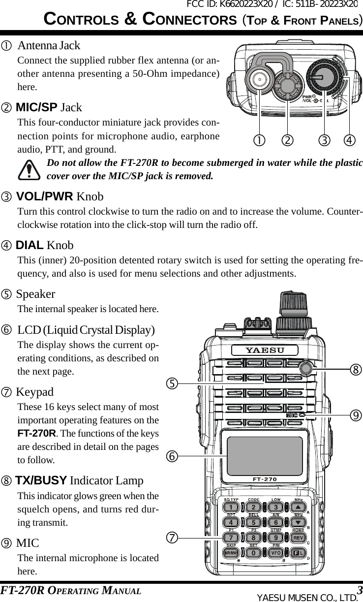
![LOCK KEYPress and hold in the [F/L] key forone second to lock all key functionsexcept the VOL Knob, PTT andMONI Switches.FREQUENCY DIAL KNOBRotate the DIAL knob to select theoperating frequency.POWER SWITCH AND VOL KNOBRotate the PWR/VOL knob to turn theradio on and adjust the Audio VolumeLevel.MONI SWITCHPress MONI Switch to disablethe noise squelching action.MICROPHONETRANSMISSION SWITCHSpeak into the microphonein a normal voice level whilepressing the PTT switch.FCC ID: K6620223X20 / IC: 511B-20223X20YAESU MUSEN CO., LTD.](https://usermanual.wiki/Yaesu-Musen/20223X20.User-Manual/User-Guide-2015216-Page-3.png)
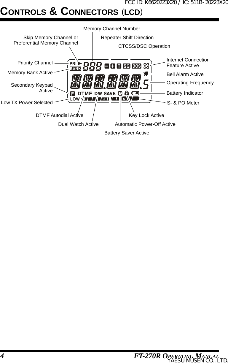
![Press KeyFrequency entry digit “1.”Frequency entry digit “2.” Frequency entry digit “3.”Frequency entry digit “4.”Frequency entry digit “5.”Frequency entry digit “6.”Frequency entry digit “7.”Frequency entry digit “8.”Frequency entry digit “9.”Activates the Internet Con-nection feature.Frequency entry digit “0.”Sets the frequency control tothe Memory Recall mode.Activates the “Memory“Tune” mode while in theMemory Recall mode.Sets frequency control tothe VFO mode.Toggles the VFO between“VFO A” and “VFO B”while in the VFO mode.Increasser the VFO fre-quency by one step or movesthe memory channel to thenext-highest channel.Decreases the VFO fre-quency by one step or movesthe memory channel to thenext-lowest channel.Reverses the transmit andreceive frequencies whileworking through a repeater.Activates the “Alternate”key function.KEY OVERVIEWPress [F/L] + KeyActivates the CTCSS orDCS Operation.Selects the CTCSS tone orDCS code number.Selects the desired trans-mit power output level.Selects the direction of theuplink frequency shift dur-ing repeater operation.Selects the CTCSS/DCSBell ringer repetitions.Toggles the display indica-tion between “frequency”and the channel’s “Alpha/Numeric Tag”.Selects the Scan ResumeMode.Selects the LCD/KeypadLamp Mode.Selects the DTMF Mode.Engages the Set (Menu)Mode.Selects the Memory Scan“Skip” channel-selectionmode.Activates the Priority(Dual Watch) function.Tunes the VFO frequencyupward in 1 MHz steps.Tunes the VFO frequencydownward in 1 MHz steps.Switches to the “Home”(favorite frequency) Chan-nel.Disables the “Alternate”key function.Press & Hold KeyToggles the “Weather”broadcast channel memorybank on/off.Activates the ARTS fea-ture.Activates the Smart Searchfeature.Activates the EMER-GENCY function.Starts the programmablescanner upward (toward ahigher frequency or ahigher channel number).Enables Internet accesscode selection.Activates the “MemoryWrite” mode (for memorychannel storage).Selects the Band width forthe VFO scanner. Selectsthe Memory Bank while inthe Memory Recall mode.Starts the scanner upward.(toward a higher frequencyor a higher channel num-ber).Starts the scanner down-ward. (toward a lower fre-quency or a lower channelnumber).Activates the Key Lockoutfeature.FCC ID: K6620223X20 / IC: 511B-20223X20YAESU MUSEN CO., LTD.](https://usermanual.wiki/Yaesu-Musen/20223X20.User-Manual/User-Guide-2015216-Page-4.png)
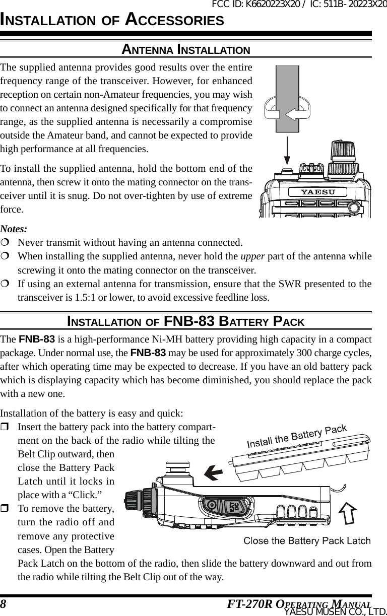
![FT-270R OPERATING MANUAL 5 PTT (Push To Talk) SwitchPress this switch to transmit, and release it (to receive) after your transmission iscompleted. MONI SwitchPressing this switch disables the noise squelching action, allowing you to hear veryweak signals near the background noise level temporarily.Press the [F/L] key on the keypad first, then press this switch to enable to adjustmentof the squelch threshold level. EXT DC JackThis coaxial DC jack allows connection to an external DC power source (6-16V DC).The center pin of this jack is the Positive (+) connection.Do not allow the FT-270R to become submerged in water while the rubbercap over the EXT DC jack is removed.CONTROLS & CONNECTORS (SIDE PANEL)FCC ID: K6620223X20 / IC: 511B-20223X20YAESU MUSEN CO., LTD.](https://usermanual.wiki/Yaesu-Musen/20223X20.User-Manual/User-Guide-2015216-Page-9.png)
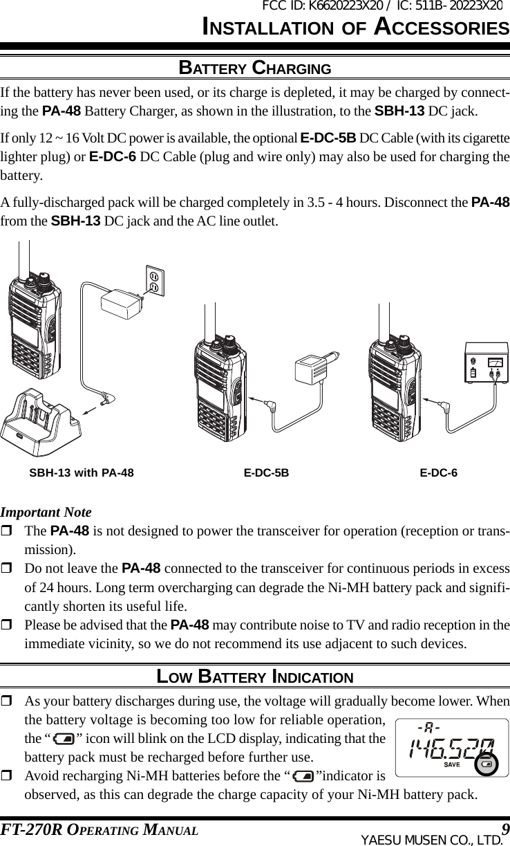
![FT-270R OPERATING MANUAL6CONTROLS & CONNECTORS (KEYPAD FUNCTIONS)Primary Function(PRESS KEY)Secondary Function(PRESS [F/L] + KEY)Third Function(PRESS & HOLD KEY)Frequency entry digit “1.” Frequency entry digit “2.”Frequency entry digit “4.” Frequency entry digit “5.”Frequency entry digit “7.” Frequency entry digit “8.”Activates the Internet Connectionfeature.Frequency entry digit “0.”Activates the CTCSS orDCS Operation.Toggles the “Weather” broadcastchannel memory bank on/off.Selects the CTCSS tone orDCS code number.Activates the ARTS feature.Selects the direction of the uplinkfrequency shift (either “–,” “+,” or“simplex”) during repeater operation.Activates the EMERGENCYfunction.Selects the CTCSS/DCS Bell ringerrepetitions.NoneSelects the Scan Resume Mode.None NoneSets the frequency control to theMemory Recall mode.Activates the “Memory “Tune” modewhile in the Memory Recall mode.Selects the Memory Scan “Skip”channel-selection mode. Engages the Set (Menu) Mode.Enables Internet access codeselection.Primary Function(PRESS KEY)Secondary Function(PRESS [F/L] + KEY)Third Function(PRESS & HOLD KEY)Primary Function(PRESS KEY)Secondary Function(PRESS [F/L] + KEY)Third Function(PRESS & HOLD KEY)Primary Function(PRESS KEY)Secondary Function(PRESS [F/L] + KEY)Third Function(PRESS & HOLD KEY)1:You can program the secondary (press [F/L] key +) function of the key to another function, ifdesired. See page 59 for details.11Selects the LCD/KeypadLamp Mode.Activates the “Memory Write” mode(for memory channel storage).FCC ID: K6620223X20 / IC: 511B-20223X20YAESU MUSEN CO., LTD.](https://usermanual.wiki/Yaesu-Musen/20223X20.User-Manual/User-Guide-2015216-Page-10.png)
![FT-270R OPERATING MANUAL 7CONTROLS & CONNECTORS (KEYPAD FUNCTIONS)Frequency entry digit “3.”Frequency entry digit “6.”Frequency entry digit “9.”Selects the desired transmit poweroutput level.Activates the Smart Search feature.Increases the VFO frequency byone step or moves the memorychannel to the next-highest channel.Tunes the VFO frequencyupward in 1 MHz steps.Starts the scanner upward(toward a higher frequency ora higher channel number).Toggles the display indicationbetween “frequency” and thechannel’s “Alpha/Numeric Tag”.Starts the programmable scannerupward (toward a higher frequencyor a higher channel number)Decreases the VFO frequency byone step or moves the memorychannel to the next-lowest channel.Tunes the VFO frequencydownward in 1 MHz steps.Starts the scanner downward(toward a lower frequency ora lower channel number).Selects the DTMF mode.NoneReverses the transmit and receivefrequencies while working through arepeater.Switches to the “Home” (favoritefrequency) Channel.NoneSets frequency control to the VFO mode.Toggles the VFO between “VFO A” and“VFO B” while in the VFO mode.Activates the Priority (Dual Watch)function.Selects the Band width for the VFOscanner.Selects the Memory Bank while in theMemory Recall mode.Activates the “Alternate” keyfunction.Disables the “Alternate” keyfunction.Activates the Key Lockout feature.Primary Function(PRESS KEY)Secondary Function(PRESS [F/L] + KEY)Third Function(PRESS & HOLD KEY)Primary Function(PRESS KEY)Secondary Function(PRESS [F/L] + KEY)Third Function(PRESS & HOLD KEY)Primary Function(PRESS KEY)Secondary Function(PRESS [F/L] + KEY)Third Function(PRESS & HOLD KEY)Primary Function(PRESS KEY)Secondary Function(PRESS [F/L] + KEY)Third Function(PRESS & HOLD KEY)2:You can exchange the function between the primary (press key) function and secondary(press [F/L] key +) function, if desired. See page 77 for details.2FCC ID: K6620223X20 / IC: 511B-20223X20YAESU MUSEN CO., LTD.](https://usermanual.wiki/Yaesu-Musen/20223X20.User-Manual/User-Guide-2015216-Page-11.png)
![FT-270R OPERATING MANUAL 13OPERATIONSQUELCH ADJUSTMENTTo set the squelch, press the [F/L] key, followed by the MONI switch just below thePTT switch on the left side of the transceiver.Now rotate the DIAL (outer knob) to find the lowestsetting (“LVL 1LVL 1LVL 1LVL 1LVL 1” through “LVL 15LVL 15LVL 15LVL 15LVL 15”) that will justsilence the background noise. Do not use a higher set-ting than necessary, or sensitivity to weak incomingsignals will be degraded.Press the PTT switch momentarily when you’ve madethe new setting; this will return you to normal operation (without having transmitted).1) A special “RF Squelch” feature is provided on this radio. This featureallows you to set the squelch so that only signals exceeding a certain S-meterlevel will open the squelch. See page 18 for details.2) If you’re operating in an area of high RF pollution, you may need to consider “ToneSquelch” operation using the built-in CTCSS Decoder. This feature will keep your radioquiet until a call is received from a station sending a carrier which contains a matching(subaudible) CTCSS tone. Or, if your friends have radios equipped with DCS (DigitalCoded Squelch) like your FT-270R has, try using that mode for silent monitoring of busychannels.FREQUENCY NAVIGATIONThe FT-270R will initially be operating in the “VFO” mode, a channelized system whichallows free tuning throughout the currently-selected operating band.Three basic frequency navigation methods are available on the FT-270R:1) Tuning DialRotation of the DIAL (outer knob) allows tuning in the pre-programmed steps establishedfor the current operating band. Clockwise rotation of the DIAL causes the FT-270R to betuned toward a higher frequency, while counter-clockwiserotation will lower the operating frequency.If you press the [F/L] key momentarily, then rotate the DIAL,frequency steps of 1 MHz will be selected. This feature isextremely useful for making rapid frequency excursions overthe wide tuning range of the FT-270R.FCC ID: K6620223X20 / IC: 511B-20223X20YAESU MUSEN CO., LTD.](https://usermanual.wiki/Yaesu-Musen/20223X20.User-Manual/User-Guide-2015216-Page-17.png)
![FT-270R OPERATING MANUAL142) Direct Keypad Frequency EntryThe desired operating frequency may be entered directly from the keypad. The first “1” inthe frequency does not need to be entered, as it is “assumed” by the microprocessor.To enter a frequency directly, just key in the 10 MHz, 1 MHz, and the kHz digits.Examples:To enter 146.560 MHz, press [4] [6] [5] [6] [0]To enter 146.5625 MHz (12.5 kHz steps), [4] [6] [5] [6] [2]3) ScanningPress and hold in either the [(MHz)] or [(MHz)] key forone second to initiate upward or downward scanning, re-spectively (Manual VFO Scan).For scanning within a limited sub-band range, from the VFOmode, press and hold in the [6(A/N)] key for one second tobegin scanning toward a higher frequency within the previ-ously-defined sub-band (Programmed VFO Scan). Detailsregarding sub-band setup may be found on page 37.If you wish to reverse the direction of the scan (i.e. toward alower frequency, instead of a higher frequency), just rotatethe DIAL one click in the counter-clockwise direction whilethe FT-270R is scanning. The scanning direction will bereversed. To revert to scanning toward a higher frequencyonce more, rotate the DIAL one click clockwise.The scanner will stop when it receives a signal strong enough to break through the Squelchthreshold. The FT-270R will then hold on that frequency according to the setting of the“RESUME” mode (Set Mode Item 32: RESUMERESUMERESUMERESUMERESUME). Press the PTT switch momentarily tocancel the scanning. This only stops the scan; it does not cause transmission to occur. Seepage 38 for details regarding Scan Operation.OPERATIONFREQUENCY NAVIGATION(MANUAL VFO SCAN)(PROGRAMMED VFO SCAN)FCC ID: K6620223X20 / IC: 511B-20223X20YAESU MUSEN CO., LTD.](https://usermanual.wiki/Yaesu-Musen/20223X20.User-Manual/User-Guide-2015216-Page-18.png)
![FT-270R OPERATING MANUAL 15OPERATIONTRANSMISSIONOnce you have set up an appropriate frequency inside the 144 MHz Amateur band onwhich the FT-270R can transmit, you’re ready to go on the air! These are the most basicsteps; more advanced aspects of transmitter operation will be discussed later.To transmit, press the PTT switch, and speak into thefront panel microphone (located in the lower left-handcorner of the speaker grille) in a normal voice level. TheTX/BUSY indicator will glow red during transmission.To return to the receive mode, release the PTT switch.During transmission, the relative power level will beindicated on the bar graph at the bottom of the LCD;full scale deflection confirms “High Power” operation, whiledeflection of two bars indicates “Low Power” operation. Fivebars indicate “Medium Power” operation. Additionally, the“LOW” icon will appear at the bottom of the display while oper-ating on the “Low Power” and “Medium Power” settings.1) If you’re just talking to friends in the immediate area,you’ll get much longer battery life by switching to LowPower operation, described in the next chapter. And don’tforget: always have an antenna connected when you transmit.2) Transmission is possible only on the 144 MHz amateur band.Changing the Transmitter Power LevelTo change the power level:Press the [F/L] key, then press the [3(LOW)] key. TheLCD shows the current power output level.Rotate the DIAL knob to select the desired power out-put level. Available selections are “HIGHHIGHHIGHHIGHHIGH” (5 W),“MIDMIDMIDMIDMID” (2 W), and “LOWLOWLOWLOWLOW” (0.5 W).When you have made your choice, press the PTT switchto save the new setting and return to normal operation.1) The FT-270R is smart! When you store memories, you can store the poweroutput settings separately in each memory, so you don’t waste battery powerwhen using very close-in repeaters!2) When you are operating on the “Low” or “Medium” power setting, you can press the[F/L] key, then press the PTT switch, to cause the FT-270R to transmit (temporarily) onHigh power. After one transmission, the power level will revert to the previously-selected(“Low” or “Medium” power) setting.“LOW” POWER“MID” POWER“HIGH” POWERFCC ID: K6620223X20 / IC: 511B-20223X20YAESU MUSEN CO., LTD.](https://usermanual.wiki/Yaesu-Musen/20223X20.User-Manual/User-Guide-2015216-Page-19.png)
![FT-270R OPERATING MANUAL16Now that you’re mastered the basics of FT-270R operation, let’s learn more about some ofthe really neat features.KEYBOARD LOCKINGTo activate the locking feature, press and hold in the [F/L] key forone second. The “ ” icon will appear on the LCD. To cancel lockingpress and hold in the [F/L] key again for one second.In order to prevent accidental frequency change or inadvertent trans-mission, various aspects of the FT-270R’s DIAL and keypad may be locked out. You maychange the lockout combinations.To lock out some or all of the keys:1. Press the [F/L] key, then press the [0(SET)] key to enter the Setmode.2. Rotate the DIAL knob to select Set Mode Item 26: LOCKLOCKLOCKLOCKLOCK.3. Press the [F/L] key momentarily to enable adjustment of thisItem.4. Rotate the DIAL knob to the desired locking scheme as listedbelow:LK KEYLK KEYLK KEYLK KEYLK KEY:Just the front panel keypad is locked outLKDIALLKDIALLKDIALLKDIALLKDIAL: Just the top panel DIAL is locked outLK K+DLK K+DLK K+DLK K+DLK K+D: Both the keypad and DIAL are locked out (factory default)LK PTTLK PTTLK PTTLK PTTLK PTT: The PTT switch is locked out (TX not possible)LK P+KLK P+KLK P+KLK P+KLK P+K: Both the PTT switch and keypad are locked outLK P+DLK P+DLK P+DLK P+DLK P+D: Both the PTT switch and DIAL are locked outLK ALLLK ALLLK ALLLK ALLLK ALL:All of the above are locked out5. When you have made your selection, press the PTT switch to save the new settingand return to normal operation.ADVANCED OPERATIONFCC ID: K6620223X20 / IC: 511B-20223X20YAESU MUSEN CO., LTD.](https://usermanual.wiki/Yaesu-Musen/20223X20.User-Manual/User-Guide-2015216-Page-20.png)
![FT-270R OPERATING MANUAL 17ADVANCED OPERATIONKEYPAD/LCD ILLUMINATIONYour FT-270R includes a reddish illumination lamp which aids in nighttime operation. Thereddish illumination yields clear viewing of the display in a dark environment, with minimaldegradation of your night vision.Three options for activating the lamp are provided:KEYKEYKEYKEYKEY Mode: Illuminates the Keypad/LCD lamp for five seconds when you rotate theDIAL knob or press the keypad or any switch (except PTT switch).This is the factory-programmed default setting.CONTCONTCONTCONTCONT Mode:Illuminates the Keypad/LCD lamp continuously.OFFOFFOFFOFFOFF Mode: Disables the Keypad/LCD lamp.Here is the procedure for setting up the Lamp operating mode:1. Press the [F/L] key, then press the [0(SET)] key to enter the Setmode.2. Rotate the DIAL knob to select Set Mode Item 25: LAMPLAMPLAMPLAMPLAMP.3. Press the [F/L] key momentarily to enable adjustment of thisItem.4. Rotate the DIAL knob to select one of the three modes describedabove.5. When you have made your choice, press the PTT switch to save the new setting andreturn to normal operation.DISABLING THE KEYPAD BEEPERA keypad beeper provides useful audible feedback whenever a keypad is pressed.If you want to turn the beep off:1. Press the [F/L] key, then press the [0(SET)] key to enter the Set mode.2. Rotate the DIAL knob to select Set Mode Item 6: BEEPBEEPBEEPBEEPBEEP.3. Press the [F/L] key momentarily to enable adjustment of thisItem.4. Rotate the DIAL knob to change the setting to “OFFOFFOFFOFFOFF.”5. Press the PTT switch to save the new setting and return tonormal operation.6. To turn the beep back on again, select “KEYKEYKEYKEYKEY” or “KEY+SCKEY+SCKEY+SCKEY+SCKEY+SC(factory default)” in step 4 above.KEYKEYKEYKEYKEY: The beeper sounds when you press the keypad.KEY+SCKEY+SCKEY+SCKEY+SCKEY+SC:The beeper sounds when you press the keypad, or when the scanner stops.FCC ID: K6620223X20 / IC: 511B-20223X20YAESU MUSEN CO., LTD.](https://usermanual.wiki/Yaesu-Musen/20223X20.User-Manual/User-Guide-2015216-Page-21.png)
![FT-270R OPERATING MANUAL18ADVANCED OPERATIONRF SQUELCHA special RF Squelch feature is provided on this radio. This feature allows you to set thesquelch so that only signals exceeding a certain S-meter level will open the squelch.To set up the RF squelch circuit for operation, use the following procedure:1. Press the [F/L] key, then press the [0(SET)] key to enter the Set mode.2. Rotate the DIAL knob to select Set Mode Item 34: RF SQLRF SQLRF SQLRF SQLRF SQL.3. Press the [F/L] key momentarily to enable adjustment of thisItem.4. Rotate the DIAL knob to select the desired signal strength levelfor the squelch threshold (S-1S-1S-1S-1S-1, S-2S-2S-2S-2S-2, S-3S-3S-3S-3S-3, S-4S-4S-4S-4S-4, S-5S-5S-5S-5S-5, S-6S-6S-6S-6S-6, S-8S-8S-8S-8S-8,S-FULLS-FULLS-FULLS-FULLS-FULL, or OFFOFFOFFOFFOFF).5. Press the PTT switch to save the new setting and return tonormal operation.CHECKING THE BATTERY VOLTAGEThe FT-270R’s microprocessor includes programming which will measure the current bat-tery voltage.1. Press the [F/L] key, then press the [0(SET)] key to enter the Setmode.2. Rotate the DIAL knob to select Set Mode Item 12: DC VLTDC VLTDC VLTDC VLTDC VLT.3. Press the [F/L] key momentarily to display the current DC volt-age being supplied.4. Press the [F/L] key, followed by the PTT switch to return tonormal operation.FCC ID: K6620223X20 / IC: 511B-20223X20YAESU MUSEN CO., LTD.](https://usermanual.wiki/Yaesu-Musen/20223X20.User-Manual/User-Guide-2015216-Page-22.png)
![FT-270R OPERATING MANUAL 19REPEATER OPERATIONRepeater stations, usually located on mountaintops or other high locations, provide adramatic extension of the communication range for low-powered hand-held or mobile trans-ceivers. The FT-270R includes a number of features which make repeater operation simpleand enjoyable.REPEATER SHIFTSThe FT-270R has been configured, at the factory, with the repeater shift set to 600 kHz.Depending on the part of the band in whichyou are operating, the repeater shift may beeither downward (–) or upward (+), and one ofthese icons will appear at the top of the LCDwhen repeater shifts have been enabled.AUTOMATIC REPEATER SHIFT (ARS)The FT-270R provides a convenient Automatic Repeater Shift feature, which causes theappropriate repeater shift to be applied automatically whenever you tune into the desig-nated repeater sub-bands in your country. These sub-bands are shown below.If the ARS feature does not appear to be working, you may have accidentally disabled it.To re-enable ARS:1. Press the [F/L] key, then press the [0(SET)] key to enter the Set mode.2. Rotate the DIAL knob to select Set Mode Item 4: ARSARSARSARSARS.3. Press the [F/L] key momentarily to enable adjustment of thisItem.4. Rotate the DIAL knob to select “ARS. ONARS. ONARS. ONARS. ONARS. ON.”5. When you have made your selection, press the PTT switch tosave the new setting and return to normal operation.EXP VersionUSA Version145.1 145.5145.6 145.8146.0 146.4 147.0 147.6 148.0146.6 147.4ARS-Repeater SubbandsFCC ID: K6620223X20 / IC: 511B-20223X20YAESU MUSEN CO., LTD.](https://usermanual.wiki/Yaesu-Musen/20223X20.User-Manual/User-Guide-2015216-Page-23.png)
![FT-270R OPERATING MANUAL20MANUAL REPEATER SHIFT ACTIVATIONIf the ARS feature has been disabled, or if you need to set a repeater shift direction otherthan that established by the ARS, you may set the direction of the repeater shift manually.To do this:1. Press the [F/L] key, then press the [4(RPT)] key to enable selection of the repeatershift direction.2. This provides a “short-cut” to Set Mode Item 35: RPT.MODRPT.MODRPT.MODRPT.MODRPT.MOD.3. Rotate the DIAL knob to select the desired shift among “RPT.–RPT.–RPT.–RPT.–RPT.–,”“RPT.+RPT.+RPT.+RPT.+RPT.+,” and “RPT.OFFRPT.OFFRPT.OFFRPT.OFFRPT.OFF.”4. When you have made your selection, press the PTT switch to save the new setting andreturn to normal operation.If you make a change in the shift direction, but still have Automatic RepeaterShift still engaged (see previous section), when you change frequency (byrotating the DIAL knob, for example) the ARS will over-ride your manualsetting of the shift direction. Turn ARS off if you do not wish this to happen.If you make a change in the repeater shift on a memory channel that you already stored, theradio will consider this a “temporary” change unless you store the memory once more, thistime with the desired repeater shift engaged.Changing the Default Repeater ShiftsIf you travel to a different region, you may need to change the default repeater shift so asto ensure compatibility with local operating requirements.To do this, follow the procedure below:1. Press the [F/L] key, then press the [0(SET)] key to enter the Setmode.2. Rotate the DIAL knob to select Set Mode Item 41: SHIFTSHIFTSHIFTSHIFTSHIFT.3. Press the [F/L] key momentarily to enable adjustment of thisItem.4. Rotate the DIAL knob to select the new repeater shift magni-tude.5. When you have made your selection, press the PTT switch to save the new settingand return to normal operation.If you just have one “odd” split that you need to program, don’t change the“default” repeated shifts using this Set Mode Item. Enter the transmit andreceive frequencies separately, as shown on page 29.REPEATER OPERATIONFCC ID: K6620223X20 / IC: 511B-20223X20YAESU MUSEN CO., LTD.](https://usermanual.wiki/Yaesu-Musen/20223X20.User-Manual/User-Guide-2015216-Page-24.png)
![FT-270R OPERATING MANUAL 21REPEATER OPERATIONMANUAL REPEATER SHIFT ACTIVATIONChecking the Repeater Uplink (Input) FrequencyIt often is helpful to be able to check the uplink (input) frequency of a repeater, to see if thecalling station is within direct (“Simplex”) range.To do this, just press the [REV(HOME)] key. You’ll noticethat the display has shifted to the repeater uplink frequency.Press the [REV(HOME)] key again to cause operation torevert to normal monitoring of the repeater downlink (out-put) frequency. While you are listening on the input fre-quency to the repeater using the [REV(HOME)] key, therepeater offset icon will blink.The configuration of this key may be set either to “RV” (for checking the input fre-quency of a repeater), or “HM” (for instant switching to the “Home” channel for theband you are operating on). To change the configuration of this key, use Set Mode Item33: REV/HM. See page 77.VFO SPLIT MODEFor working on repeaters with odd splits, or communicating with astronauts on orbitingspace vehicles, it may be necessary to use non-standard splits between the receive andtransmit frequency. If the application is infrequent enough not to warrant the dedication ofa memory channel for this purpose, the “VFO Split” mode may be used. Here is the proce-dure for going Split:1. Press the [VFO(PRI)] key, as needed, to select VFO-A. Set VFO-A for the desiredreceiving (downlink) frequency (e.g.145.800 MHz).2. Now press the [VFO(PRI)] key, and set VFO-B for the desired transmit (uplink) fre-quency (e.g. 144.490 MHz).3. Press the [VFO(PRI)] key once more to re-establish VFO-A as the “Main” (receive)VFO.4. Press the [F/L] key, then press the [0(SET)] key to enter the Set mode.5. Rotate the DIAL to select Set Mode Item 50: VFO.SPLVFO.SPLVFO.SPLVFO.SPLVFO.SPL.6. Press the [F/L] key, then rotate the DIAL to set this function“VSP. ONVSP. ONVSP. ONVSP. ONVSP. ON.”7. Press the PTT switch once to save the new setting and exit tonormal operation.8. You will now be operating in the Split mode. When you pressthe PTT switch to transmit, you will observe that VFO-A andVFO-B will reverse positions. The VFO selection indicator “-b-” will blink while thetransceiver is transmitting, this means that the VFO Split feature is now activated.FCC ID: K6620223X20 / IC: 511B-20223X20YAESU MUSEN CO., LTD.](https://usermanual.wiki/Yaesu-Musen/20223X20.User-Manual/User-Guide-2015216-Page-25.png)
![FT-270R OPERATING MANUAL229. If you need to modify the VFO-B (transmit) frequency (for Doppler Shift correction,etc.), just press the [VFO(PRI)] key, then make the necessary change, then press[VFO(PRI)] key once more to restore VFO-A to the “receive VFO” position.10. When you have finished with Split operation, re-enter the Set mode, and change SetMode Item 50: VFO.SPLVFO.SPLVFO.SPLVFO.SPLVFO.SPL to “VSP.OFFVSP.OFFVSP.OFFVSP.OFFVSP.OFF.”A split frequency pair set up via the VFO Split feature cannot be stored directly intomemory. You can, however, store odd frequency pairs using a different (slightly simpler)procedure. See page 29.VFO SPLIT MODEREPEATER OPERATIONFCC ID: K6620223X20 / IC: 511B-20223X20YAESU MUSEN CO., LTD.](https://usermanual.wiki/Yaesu-Musen/20223X20.User-Manual/User-Guide-2015216-Page-26.png)
![FT-270R OPERATING MANUAL 23CTCSS/DCS/EPCS OPERATIONCTCSS OPERATIONMany repeater systems require that a very-low-frequency audio tone be superimposed onyour FM carrier in order to activate the repeater. This helps prevent false activation of therepeater by radar or spurious signals from other transmitters. This tone system, called“CTCSS” (Continuous Tone Coded Squelch System), is included in your FT-270R, and isvery easy to activate.CTCSS setup involves two actions: setting the Tone Mode and then setting ofthe Tone Frequency. These actions are set up by using the [1(SQ TYP)] keyand [2(CODE)] keys.1. Press the [F/L] key, then press the [1(SQ TYP)] key to enable selection of the CTCSS/DCS/ECS mode.2. Rotate the DIAL knob so that “TONETONETONETONETONE” indication appears onthe display; this activates the CTCSS Encoder, for access torepeaters requiring a CTCSS tone.3. Rotation of the DIAL knob one more “click” in step “2” abovewill cause the “TSQLTSQLTSQLTSQLTSQL” notation to appear. When “TSQLTSQLTSQLTSQLTSQL” isdisplayed, this means that the Tone SQueLch system is active,which mutes your FT-270R’s receiver until it receives a call fromanother radio sending out a matching CTCSS tone. This canhelp keep your radio quiet until a specific call is received, which may be helpful whileoperating in congested areas of the band.1) You may notice a “REV TN” indication on the display while you rotatethe DIAL knob in this step; this means that the Reverse Tone Squelchsystem is active, which mutes your FT-270R’s receiver (instead of openingthe squelch) when it receives a call from the radio sending a matchedCTCSS tone. The “ ” icon will blink on the display when the Reverse ToneSquelch system is activated.2) You may notice the “DCS” and “ECS” indications on the display while you rotatethe DIAL knob still more. We’ll discuss the Digital Code Squelch system (for “DCS”)and Enhanced Paging & Code Squelch (for “ECS”) later.4. When you have made your selection of the CTCSS tone mode, press the PTT switchto save the new setting.5. Press the [F/L] key, then press the[2(CODE)] key to enable adjustment ofthe CTCSS fre-quency.6. Rotate the DIALknob until the dis-play indicates the Tone Frequency youneed to be using (ask the repeater owner/CTCSS TONE FREQUENCY (Hz) 67.0 69.3 71.9 74.4 77.0 79.7 82.5 85.4 88.5 91.5 94.8 97.4100.0 103.5 107.2 110.9 114.8 118.8123.0 127.3 131.8 136.5 141.3 146.2151.4 156.7 159.8 162.2 165.5 167.9171.3 173.8 177.3 179.9 183.5 186.2189.9 192.8 196.6 199.5 203.5 206.5210.7 218.1 225.7 229.1 233.6 241.8250.3 254.1 ––––FCC ID: K6620223X20 / IC: 511B-20223X20YAESU MUSEN CO., LTD.](https://usermanual.wiki/Yaesu-Musen/20223X20.User-Manual/User-Guide-2015216-Page-27.png)
![FT-270R OPERATING MANUAL24operator if you don’t know the tone frequency).7. When you have made your selection, press the [F/L] key momentarily to save the newsettings and exit to normal operation. This is different than the usual method of restor-ing normal operation, and it applies only to the configuration of the CTCSS/DCSfrequencies.Your repeater may or may not re-transmit a CTCSS tone - some systems justuse CTCSS to control access to the repeater, but don’t pass it along whentransmitting. If the S-Meter deflects, but the FT-270R is not passing audio,repeat steps “1” through “4” above, but rotate the DIAL so that “TSQ” disappears - thiswill allow you to hear all traffic on the channel being utilized.DCS OPERATIONAnother form of tone access control is Digital Code Squelch, or DCS. It is a newer, moreadvanced tone system which generally provides more immunity from false paging thandoes CTCSS. The DCS Encoder/Decoder is built into your FT-270R, and operation is verysimilar to that just described for CTCSS. Your repeater system may be configured forDCS; if not, DCS is frequently quite useful in Simplex operation if your friend(s) usetransceivers equipped with this advanced feature.Just as in CTCSS operation, DCS requires that you set the Tone Mode to DCS and thatyou select a tone code.1. Press the [F/L] key, then press the [1(SQ TYP)] key to enable selection of the CTCSS/DCS/ECS mode.2. Rotate the DIAL knob until the “DCSDCSDCSDCSDCS” indication appears on thedisplay; this activates the DCS Encoder/Decoder.3. Press the PTT switch to save the new setting.4. Press the [F/L] key, then press the [2(CODE)] key to enable adjustment of the DCS code.5. Rotate the DIAL knob to select the desired DCS Code (a three-digit number). Ask therepeater owner/operator if you don’tknow DCS Code; ifyou are workingsimplex, just set upthe DCS Code tobe the same as that used by your friend(s).6. When you have made your selection,press the [F/L] key momentarily to savethe new settings and exit to normal opera-tion.CTCSS OPERATIONCTCSS/DCS/EPCS OPERATIONDCS CODE023 025 026 031 032 036 043 047 051 053054 065 071 072 073 074 114 115 116 122125 131 132 134 143 145 152 155 156 162165 172 174 205 212 223 225 226 243 244245 246 251 252 255 261 263 265 266 271274 306 311 315 325 331 332 343 346 351356 364 365 371 411 412 413 423 431 432445 446 452 454 455 462 464 465 466 503506 516 523 526 532 546 565 606 612 624627 631 632 654 662 664 703 712 723 731732 734 743 754 – – – – – –FCC ID: K6620223X20 / IC: 511B-20223X20YAESU MUSEN CO., LTD.](https://usermanual.wiki/Yaesu-Musen/20223X20.User-Manual/User-Guide-2015216-Page-28.png)
![FT-270R OPERATING MANUAL 25CTCSS/DCS/EPCS OPERATIONRemember that the DCS is an Encode/Decode system, so your receiver willremain muted until a matching DCS code is received on an incoming trans-mission. Switch the DCS off when you’re just tuning around the band!TONE SEARCH SCANNINGIn operating situations where you don’t know the CTCSS or DCS tone being used byanother station or stations, you can command the radio to listen to the incoming signal andscan in search of the tone being used. Two things must be remembered in this regard:You must be sure that your repeater uses the same tone type (CTCSS vs. DCS).Some repeaters do not pass the CTCSS tone; you may have to listen to the station(s)transmitting on the repeater uplink (input) frequency in order to allow Tone SearchScanning to work.To scan for the tone in use:1. Set the radio up for either CTCSS or DCS Decoder operation (see the previous discus-sions). In the case of CTCSS, “ ” will appear on the display; in the case of DCS,“” will appear on the display.2. Press the [F/L] key, then press the [2(CODE)] key.3. Press and hold in the [(MHz)] or [(MHz)] key for one sec-ond to start scanning for the incoming CTCSS or DCS tone/code.4. When the radio detects the correct tone or code, it will halt onthat tone/code, and audio will be allowed to pass. Press the [F/L]key to lock in that tone/code, then press the [F/L] key again toexit to normal operation.If the Tone Scan feature does not detect a tone or code, it will continue to scanindefinitely. When this happens, it may be that the other station is not sendingany tone. You can press the PTT switch to halt the scan at any time.You also can press the MONI key during Tone Scanning to listen to the (muted) signal fromthe other station. When you release the MONI key, Tone Scanning will resume after abouta second.Tone Scanning works either in the VFO or Memory modes.DCS OPERATIONFCC ID: K6620223X20 / IC: 511B-20223X20YAESU MUSEN CO., LTD.](https://usermanual.wiki/Yaesu-Musen/20223X20.User-Manual/User-Guide-2015216-Page-29.png)
![FT-270R OPERATING MANUAL26EPCS (ENHANCED PAGING & CODE SQUELCH)The FT-270R includes an Enhanced CTCSS tone encoder/decoder and a dedicated micropro-cessor providing paging and selective calling features. This allows you to place a call to a specificstation (Paging), and to receive calls of your choice directed only to you (Code Squelch).The paging and code squelch systems use two pairs of (alternately switched) CTCSS toneswhich are stored in the pager memories. Basically, your receiver remains silent until itreceives the CTCSS tone pair that matches those stored in the Receiving Pager Memory.The squelch then opens so the caller is heard, and the paging ringer immediately sounds, ifactivated. When you close the PTT switch to transmit, the CTCSS tone pair which isstored in the Transmitting Pager Memory will be transmitted automatically.On the paged radio, the squelch will close automatically after the incoming page ends.Storing the CTCSS Tone Pairs for EPCS Operation1. Press the [F/L] key, then press the [0(SET)] key to enter the Set mode.2. Rotate the DIAL knob to select Set Mode Item 18: ECS.CDRECS.CDRECS.CDRECS.CDRECS.CDRfor the Receiving CTCSS Tone Pair or Set Mode Item 19:ECS.CDTECS.CDTECS.CDTECS.CDTECS.CDT for the Transmitting CTCSS Tone Pair.3. Press the [F/L] key momentarily to enable adjustment of this SetMode Item.4. Rotate the DIAL knob to set the CTCSS Tone number whichcorresponds to the first tone of the CTCSS Tone Pair.5. Press the [(MHz)] or [(MHz)] key, then rotate the DIALknob to set the CTCSS Tone number which corresponds to thesecond tone of the CTCSS Tone Pair.6. Press the PTT switch to save the new setting and exit to normaloperation.The FT-270R does not recognize the order of the 1sttone and the 2nd tone. In other words, for example, theFT-270R considers both CTCSS pairs “10, 35” and “35, 10” to be identical.CTCSS/DCS/EPCS OPERATIONHz67.069.371.974.477.079.782.585.488.591.5No.01020304050607080910Hz94.897.4100.0103.5107.2110.9114.8118.8123.0127.3No.11121314151617181920Hz131.8136.5141.3146.2151.4156.7159.8162.2165.5167.9No.21222324252627282930Hz171.3173.8177.3179.9183.5186.2189.9192.8196.6199.5No.31323334353637383940Hz203.5206.5210.7218.1225.7229.1233.6241.8250.3254.1No.41424344454647484950CTCSS TONE NUMBERFCC ID: K6620223X20 / IC: 511B-20223X20YAESU MUSEN CO., LTD.](https://usermanual.wiki/Yaesu-Musen/20223X20.User-Manual/User-Guide-2015216-Page-30.png)
![FT-270R OPERATING MANUAL 27Activating the Enhanced Paging & Code Squelch System1. Press the [F/L] key, then press the [1(SQ TYP)] key to enable selection of the CTCSS/DCS/ECS mode.2. Rotate the DIAL knob so that the “ECSECSECSECSECS” indication appears onthe display.3. Press the PTT switch to save the new setting and activate theEnhanced Paging & Code Squelch.4. To disable the Enhanced Paging & Code Squelch, just repeat the above procedure,rotating the DIAL knob to select “OFFOFFOFFOFFOFF” in step 2 above.When the Enhanced Paging & Code Squelch feature is activated, the“” icon will blink on the display.CTCSS/DCS/EPCS BELL OPERATIONDuring CTCSS Decode, DCS, or EPCS operation, you may set up the FT-270R such that aringing “bell” sound alerts you to the fact that a call is coming in. Here is the procedure foractivating the CTCSS/DCS/EPCS Bell:1. Set the transceiver up for CTCSS Decode (“Tone Squelch”), DCS, or EPCS operation,as described previously.2. Adjust the operating frequency to the desired channel.3. Press the [F/L] key, then press the [5(BELL)] key.4. Rotate the DIAL knob to set the desired number of rings of theBell. The available choices are “1 T1 T1 T1 T1 T,” “3 T3 T3 T3 T3 T,” “5 T5 T5 T5 T5 T,” or “8 T8 T8 T8 T8 T”rings, CONTCONTCONTCONTCONT (continuous ringing), or OFFOFFOFFOFFOFF.5. Press the PTT switch momentarily to save the new setting and exit to normal opera-tion.When you are called by a station whose transceiver is sending a CTCSS tone, DCS code,or CTCSS code pair which matches that set into your Decoder, theBell will ring in accordance with this programming. When the CTCSS/DCS/EPCS Bell is activated, the “ ” icon will appear at the upperright corner on the LCD.CTCSS/DCS/EPCS OPERATIONEPCS (ENHANCED PAGING & CODE SQUELCH)FCC ID: K6620223X20 / IC: 511B-20223X20YAESU MUSEN CO., LTD.](https://usermanual.wiki/Yaesu-Musen/20223X20.User-Manual/User-Guide-2015216-Page-31.png)
![FT-270R OPERATING MANUAL28SPLIT TONE OPERATIONThe FT-270R can be operated in a Split Tone configuration via the Set mode.1. Press the [F/L] key, then press the [0(SET)] key to enter the Set mode.2. Rotate the DIAL knob to select Set Mode Item 43: SPLITSPLITSPLITSPLITSPLIT.3. Press the [F/L] key momentarily to enable adjustment of this SetMode Item.4. Rotate the DIAL knob to select ONONONONON (to enable the Split Tonefeature).5. Press the PTT switch momentarily to save the new setting andexit to normal operation.When the Split Tone feature is activated, you can see the following additional parametersfollowing the “DCSDCSDCSDCSDCS” parameter (while selecting the tone mode by pressing [F/L] [1(SQ TYP)]):DDDDD: DCS Encode only (the “ ” icon will blink during operation)T DCST DCST DCST DCST DCS: Encodes a CTCSS Tone and Decodes a DCS code(the “ ” icon will blink and the “ ” icon will appear during operation)D TSQLD TSQLD TSQLD TSQLD TSQL: Encodes a DCS code and Decodes a CTCSS Tone(the “ ” icon will appear and the “ ” icon will blink during operation)Select the desired operating mode from the selections shown above.TONE CALLING (1750 HZ)If the repeaters in your country require a 1750-Hz burst tone for access (typically in Eu-rope), you can set the MONI key to serve as a “Tone Call” switch instead. To change theconfiguration of this switch, we again use the Set Mode to help us.1. Press the [F/L] key, then press the [0(SET)] key to enter the Setmode.2. Rotate the DIAL knob to select Set Mode Item 27: MMMMM/T-CLT-CLT-CLT-CLT-CL.3. Press the [F/L] key momentarily to enable adjustment of this SetMode Item.4. Rotate the DIAL knob to select “T-CALLT-CALLT-CALLT-CALLT-CALL” on the display.5. Press the PTT switch to save the new setting and exit to normaloperation.To access a repeater, press and hold in the MONI key for the amount of time specified bythe repeater owner/operator. The transmitter will automatically be activated, and a 1750-Hz audio tone will be superimposed on the carrier. Once access to the repeater has beengained, you may release the MONI key, and use the PTT switch for activating the transmit-ter thereafter.CTCSS/DCS/EPCS OPERATIONFCC ID: K6620223X20 / IC: 511B-20223X20YAESU MUSEN CO., LTD.](https://usermanual.wiki/Yaesu-Musen/20223X20.User-Manual/User-Guide-2015216-Page-32.png)
![FT-270R OPERATING MANUAL 29MEMORY MODEThe FT-270R provides a wide variety of memory system resources. These include:200 “Standard” memory channels, numbered “11111” through “200200200200200.”A “Home” channel, providing storage and quick recall of one prime frequency.10 sets of band-edge memories, also known as “Programmable Memory Scan” chan-nels, labeled “L1L1L1L1L1/U1U1U1U1U1” through “L10L10L10L10L10/U10U10U10U10U10.”10 Memory Banks, labeled “BANK 1BANK 1BANK 1BANK 1BANK 1” through “BANK10BANK10BANK10BANK10BANK10.” Each Memory Bankcan be assigned up to 200 channels from the “standard” memory channels.10 “Weather Broadcast” Channels.MEMORY STORAGE1. Select the desired frequency, while operating in the VFO mode. Be sure to set up anydesired CTCSS or DCS tones, as well as any desired repeater offset, now. The powerlevel may also be set at this time, if you wish to store it.2. Press and hold in the [MR/MW(SKIP)] key for one second.3. Within ten seconds of releasing the [MR/MW(SKIP)] key, you need to make a deci-sion regarding channel storage. The microprocessor will automatically select the next-available “free” channel (a memory register on which no data has been stored), so youmay not wish to make any change; if this is the case, proceed to step 4. If you wish toselect a different channel number into which to store the data, rotate the DIAL knob toselect the desired memory channel. You may jump 10 memory channels, if you’re in ahurry (11 21 31 …) by pressing the [VFO(PRI)] key (multiple times, if necessary).4. Press the [MR/MW(SKIP)] key once more to store the frequency into memory.5. You still will be operating in the “VFO” mode, so you may now enter other frequencies,and store them into additional memory locations, by repeating the above process.Storing Independent Transmit Frequencies (“Odd Splits”)All memories can store an independent transmit frequency, for operation on repeaters withnon-standard shift. To do this:1. Store the receive frequency using the method already described under MEMORYSTORAGE (it doesn’t matter if a repeater offset is active).2. Tune to the desired transmit frequency, then press and hold in the [MR/MW(SKIP)]key for one second.3. Within ten seconds of releasing the [MR/MW(SKIP)] key, rotate the DIAL knob toselect the same memory channel number as used in step “1” above.4. Press and hold in the PTT switch. Then while holding the PTT switch in, momentarilypress the [MR/MW(SKIP)] key once more. (This does not key the transmitter).1) The “Odd Splits” feature permits setting TONE/DCS indi-vidually for transmit and receive. Briefly, press the [F/L] key,and then press the [2(CODE)] key. Rotate the DIAL knob toselect the TONE or DCS for receive. You can confirm the Transmit andreceive TONE/DCS by alternately pressing of the [REV(HOME)] key.r: receivert: transmitFCC ID: K6620223X20 / IC: 511B-20223X20YAESU MUSEN CO., LTD.](https://usermanual.wiki/Yaesu-Musen/20223X20.User-Manual/User-Guide-2015216-Page-33.png)
![FT-270R OPERATING MANUAL30MEMORY MODE2)Whenever you recall a memory which contains inde-pendently-stored transmit and receive frequencies, the“” indication will appear in the display.MEMORY RECALL1. While operating in the VFO mode, press the [MR/MW(SKIP)]key to enter the Memory mode.2. Rotate the DIAL knob to select the desired channel.3. To return to the VFO mode, press the [VFO(PRI)] key.When the radio is already set to the Memory mode, an easy way to recall memories is to keyin the memory channel number, then press the [F/L] key.For example, to recall memory channel #14, press [1(SQ TYP)] [4(RPT)] [F/L].You may also recall Programmable Memory channels (“L1L1L1L1L1/U1U1U1U1U1” through “L10L10L10L10L10/U10U10U10U10U10.”)using the following numbers: Programmable Memory channels #L1L1L1L1L1 = “201,” U1U1U1U1U1 = “202,”L10L10L10L10L10 = “219,” and U10U10U10U10U10 = “220.”HOME CHANNEL MEMORYA special one-touch “HOME” channel is available, to allow quick recall of a favorite oper-ating frequency.Home Channel storage is simple to accomplish:1. Change the setting of Set Mode Item 33: REVREVREVREVREV/HMHMHMHMHM from “REVREVREVREVREV” to “HOMEHOMEHOMEHOMEHOME,” if it isnot already set to this option (see page 77).2. Select the desired frequency, while operating in the VFO mode. Be sure to set up anydesired CTCSS or DCS tones, as well as any desired repeater offset. The power levelmay also be set at this time, if you wish to store it.3. Press and hold in the [MR/MW(SKIP)] key for one second.4. While the memory channel number is blinking, just press the [REV(HOME)] key. Thefrequency and other data (if any) will now be stored in the spe-cial HOME channel register.5. To recall the HOME channel, press the [REV(HOME)] key mo-mentarily while operating either in the VFO or MR mode.MEMORY STORAGEFCC ID: K6620223X20 / IC: 511B-20223X20YAESU MUSEN CO., LTD.](https://usermanual.wiki/Yaesu-Musen/20223X20.User-Manual/User-Guide-2015216-Page-34.png)
![FT-270R OPERATING MANUAL 31MEMORY MODELABELING MEMORIESYou may wish to append an alpha-numeric “Tag” (label) to a memory or memories, to aid inrecollection of the channel’s use (such as a club name, etc.). This is easily accomplishedusing the Set Mode.1. Recall the memory channel on which you wish to append a label.2. Press the [F/L] key, then press the [0(SET)] key to enter the Set mode.3. Rotate the DIAL knob to select Set Mode Item 29: NM WRTNM WRTNM WRTNM WRTNM WRT.4. Press the [F/L] key momentarily to display the previouslystored label (if any).5. Press the [F/L] key again to clear any previous label.6. Rotate the DIAL knob to select the first digit of the desiredlabel.7. Press the [F/L] key to move to the next character.8. If you make a mistake, press the [(MHz)] key to back-space the cursor, then re-enter the correct letter, number, orsymbol.9. Repeat steps 5 through 7 to program the remaining letters,numbers, or symbols of the desired label. A total of six charactersmay be used in the creation of a label.10. When you have programmed a label which is under 6 characters,press and hold in the [F/L] key for one second to confirm the label (if the label is exactly 6characters in length, you do not need to press and hold in [F/L] key).11. When you have completed the creation of the label, press thePTT switch to save the label and return to the memory recallmode with labeled (alpha-numeric “Tag”) display.To disable the alpha-numeric Tag (and enable the frequency display):1. Set the FT-270R to the “MR” (Memory Recall) mode, and recall the memory channelon which you wish to disable the alpha-numeric Tag.2. Press the [F/L] key, then press the [6(A/N)] key to activate the alpha-numeric Tag.3. Rotate the DIAL knob to set this to “FREQFREQFREQFREQFREQ” (enabling the fre-quency display).4. To display the alpha-numeric Tag again, just repeat the aboveprocedure.5. When you have made your selection, press the PTT switch to save the setting and exitto normal operation.To display the alpha-numeric Tag again, just repeat the above procedure, rotating the DIALknob to select “ALPHAALPHAALPHAALPHAALPHA” in step 3 above.This procedure is not applied to all memory channels at once (just the chan-nel on which you currently are operating).FCC ID: K6620223X20 / IC: 511B-20223X20YAESU MUSEN CO., LTD.](https://usermanual.wiki/Yaesu-Musen/20223X20.User-Manual/User-Guide-2015216-Page-35.png)
![FT-270R OPERATING MANUAL32MEMORY OFFSET TUNINGOnce you have recalled a particular memory channel, you may easily tune off that channel,as though you were in the “VFO” mode.1. With the FT-270R in the “MR” (Memory Recall) mode, selectthe desired memory channel.2. Press the [MR/MW(SKIP)] key momentarily to activate the“Memory Tuning” feature. The Memory Channel number will bereplaced by “tuntuntuntuntun.” And if you have an alpha-numeric Tag dis-played on the memory channel, the display will automaticallyrevert to display of the operating frequency, so you can navi-gate without having to enter the Menu to change the displayconfiguration.3. Rotate the DIAL knob, as desired, to tune to a new frequency.The synthesizer steps selected for VFO operation on the currentband will be the steps used during Memory Tuning.4. If you wish to return to the original memory frequency, just pressthe [MR(SKIP)] key momentarily. The display will revert to dis-play of the alpha-numeric Tag (if any) that may have originallyappeared on the LCD.5. If you wish to store a new frequency set during Memory Tuning, just press and holdin the [F/L] key for one second, per normal memory storage procedure. The micropro-cessor will automatically set itself to the next-available clear memory location, and youthen press [F/L] again to lock in the new frequency.1) If you want to replace the original memory contents with those of the newfrequency, be sure to rotate the DIAL knob to the original memory channelnumber!2) Any required CTCSS/DCS changes, or repeater offset modifications, must be donebefore storing the data into the new (or original) memory channel location.DELETING MEMORIESYou may delete any of the memories (except for Memory Channel “1” and the Home Chan-nel). The procedure for deleting a channel is quite simple.1. Press the [VFO(PRI)] key, if needed, to enter the MR mode.2. Press and hold in the [MR/MW(SKIP)] key for one second, then rotate the DIAL knobto select the memory channel to be deleted.3. Press the [F/L] key momentarily. The display will revert to memory channel #1. Thepreviously-selected memory will be deleted.Important Notice! Once deleted, the channel data cannot be recovered!MEMORY MODEFCC ID: K6620223X20 / IC: 511B-20223X20YAESU MUSEN CO., LTD.](https://usermanual.wiki/Yaesu-Musen/20223X20.User-Manual/User-Guide-2015216-Page-36.png)
![FT-270R OPERATING MANUAL 33MEMORY MODEMEMORY BANK OPERATIONThe large number of memories available in the FT-270R could be difficult to utilize withoutsome means of organizing them. Fortunately, the FT-270R includes provision for dividingthe memories into as many as ten Memory Groups, so you can categorize the memories ina manner convenient to you.Assigning Memories to a Memory Bank1. Recall the memory channel to be assigned to a Memory Bank.2. Press and hold in the [VFO(PRI)] key for one second, then ro-tate the DIAL knob to select the Memory Bank number you wantas the Memory Bank for this channel (“BANK 1BANK 1BANK 1BANK 1BANK 1” ~“BANK10BANK10BANK10BANK10BANK10”).3. Press and hold in the [F/L] key for one second to copy thememory channel data into the Memory Bank.1) You may assign one memory channel into multiple Memory Banks.2) The PMS memory channels (L1/U1 through L10/U10) may not be as-signed to a Memory Bank.Memory Bank Recall1. Press the [MR/MW(SKIP)] key, if needed, to enter the Memory Recall mode.2. Press and hold in the [VFO(PRI)] key, then rotate the DIALknob to select the desired Memory Bank (“BANK 1BANK 1BANK 1BANK 1BANK 1” through“BANK10BANK10BANK10BANK10BANK10”).3. Press the [MR/MW(SKIP)] key momentarily; now, as you rotatethe DIAL knob to select memories, you will observe that you canonly select memory channels in the current memory bank. The“” indication will appear at the left side of the frequencydisplay while operating within a Memory Bank.4. To change to another Memory Bank, press and hold in the [VFO(PRI)] key, rotate theDIAL knob to select the new Memory Bank, then press the [MR/MW(SKIP)] key momen-tarily.5. To exit from Memory Bank operation, select “NOBANKNOBANKNOBANKNOBANKNOBANK” instep 4 above. You are now in the “standard” Memory Recallmode, without utilization of the Memory Banks. The memoriesstored in the various Banks will remain in those banks, however;you do not need to store them again.Removing Memories from a Memory Bank1. Recall the memory channel to be removed from a Memory Bank.2. Press and hold in the [VFO(PRI)] key for one second, then press and hold in the [F/L]key to remove the memory channel data from the Memory Bank.FCC ID: K6620223X20 / IC: 511B-20223X20YAESU MUSEN CO., LTD.](https://usermanual.wiki/Yaesu-Musen/20223X20.User-Manual/User-Guide-2015216-Page-37.png)
![FT-270R OPERATING MANUAL34MOVING MEMORY DATA TO THE VFOData stored on memory channels can easily be moved to the last selected VFO, if you like.1. Select the memory channel containing the frequency data to be moved to the VFO.2. Press the [MR/MW(SKIP)] key momentarily to activate the “Memory Tune” featuretemporarily, then press and hold in the [VFO(PRI)] key for one second. The data willnow have been copied to the last selected VFO, although the original memory contentswill remain intact on the previously-stored channel.If a Split Frequency Memory channel was transferred, the TX frequency will be ignored(you will be set up for Simplex operation on the Receive frequency).MEMORY ONLY MODEOnce memory channel programming has been completed, you may place the radio in a“Memory Only” mode, whereby VFO operation is impossible. This may be particularlyuseful during public-service events, where a number of operators may be using the radiofor first time, and ultimate simplicity of channel selection is desired.To place the radio into the Memory Only mode:1. Turn the radio off.2. Press and hold in the MONI switch (just below the PTT switch)while turning the radio on.3. Rotate the DIAL knob to select the “F5 M-ONLYF5 M-ONLYF5 M-ONLYF5 M-ONLYF5 M-ONLY” option, thenpress the [F/L] key.To return to normal operation, repeat the above power-on procedure.MEMORY MODEFCC ID: K6620223X20 / IC: 511B-20223X20YAESU MUSEN CO., LTD.](https://usermanual.wiki/Yaesu-Musen/20223X20.User-Manual/User-Guide-2015216-Page-38.png)
![FT-270R OPERATING MANUAL 35MEMORY MODEWEATHER BROADCAST CHANNELSThe VHF Weather Broadcast Station Memory Channel Bank has been pre-programmed atthe factory, for quick selection of NOAA weather information stations.1. Press and hold in the [1(SQ TYP)] key for one second to recallthe Weather Broadcast Memory Bank.2. Rotate the DIAL knob to select the desired Weather Broadcastchannel.3. If you wish to scan this bank to search for louderstations, just press the PTT switch. When thescanner pauses on a station, press the PTT switchonce to halt the scan, or press it twice to restartthe scan.4. To exit to normal operation, press the [VFO(PRI)] key, or press and hold in the[1(SQ TYP)] key again.Severe Weather AlertIn the event of extreme weather disturbances, such as severe thunderstorms and hurri-canes, the NOAA (National Oceanic and Atmospheric Administration) sends a weatheralert accompanied by a 1050 Hz tone and subsequent weather report on one of the NOAAweather channels. See page 45 for details regarding activation of this mode.CH0102030405CH0607080910FREQUENCY162.550 MHz162.400 MHz162.475 MHz162.425 MHz162.450 MHzFREQUENCY162.500 MHz162.525 MHz161.650 MHz161.775 MHz163.275 MHzFCC ID: K6620223X20 / IC: 511B-20223X20YAESU MUSEN CO., LTD.](https://usermanual.wiki/Yaesu-Musen/20223X20.User-Manual/User-Guide-2015216-Page-39.png)
![FT-270R OPERATING MANUAL36The FT-270R allows you to scan just the memory channels, the entire operating band, or aportion of that band. It will halt on signals encountered, so you can talk to the station(s) onthat frequency, if you like.Scanning operation is basically the same in each of the above modes. Before you begin,take a moment to select the way in which you would like the scanner to resume scanningafter it halts on a signal.Setting the Scan-Resume TechniqueThree options for the Scan-Resume mode are available:BUSYBUSYBUSYBUSYBUSY: In this mode, the scanner will halt on a signal it encounters. Two seconds after thecarrier has dropped because the other station(s) ceased transmission, the scannerwill resume. In the case of constant-carrier signals like Weather Station broad-casts, the scanner will likely remain on this frequency indefinitely.HOLDHOLDHOLDHOLDHOLD: In this mode, the scanner will halt on a signal it encounters. It will not restartautomatically; you must manually re-initiate scanning if you wish to resume.TIMETIMETIMETIMETIME: In this mode, the scanner will halt on a signal it encounters, and will hold there forfive seconds. If you do not take action to disable the scanner within that timeperiod, the scanner will resume even if the stations are still active.To set the Scan-Resume mode:1. Press the [F/L] key, then press the [0(SET)] key to enter the Set mode.2. Rotate the DIAL knob to select Set Mode Item 32: RESUMERESUMERESUMERESUMERESUME.3. Press the [F/L] key momentarily to enable adjustment of this SetMode Item.4. Rotate the DIAL knob to select the desired scan-resume mode.5. When you have made your selection, press the PTT switch tosave the new setting and exit to normal operation.The default condition for this Set Mode Item is “BUSY.”SCANNINGSETTING THE SQUELCH LEVEL DURING ACTIVE SCANNING OPERATIONThe FT-270R allows adjustment of the Squelch level “on the fly” while you are scanning.1. While the scanner is engaged, press the [F/L] key, then press the MONI switch(the current squelch level (e.g. “S 1S 1S 1S 1S 1”) will appear in fine print above the frequencydisplay).2. Rotate the DIAL to select the desired Squelch level.3. Press the PTT switch momentarily to save the new setting and exit to normaloperation. In this case, pressing the PTT switch this one time will not causingscanning to stop.FCC ID: K6620223X20 / IC: 511B-20223X20YAESU MUSEN CO., LTD.](https://usermanual.wiki/Yaesu-Musen/20223X20.User-Manual/User-Guide-2015216-Page-40.png)
![FT-270R OPERATING MANUAL 37SCANNINGVFO SCANNINGThe FT-270R provides two VFO scanning functions: “Manual VFO Scanning” and “Pro-grammed VFO Scanning.”Manual VFO Scan1. Select the VFO mode by pressing the [VFO(PRI)] key, if necessary.2. Press and hold in either the [(MHz)] or [(MHz)] key for one second to initiateupward or downward scanning, respectively.3. If and when the scanner encounters a signal strong enough to open the squelch, thescanner will halt temporarily; the decimal point of the frequency display will blinkduring this “Pause” condition.4. The scanner will then resume according to the Scan-Resume mode selected in theprevious section.5. To cancel scanning, press the PTT switch or [VFO(PRI)] key.Programmed VFO Scan1. Select the VFO mode by pressing the [VFO(PRI)] key, if necessary.2. Press and hold in the [VFO(PRI)] key for one second, then rotate the DIAL knob toselect the bandwidth for the Programmed VFO scanner. Available selections are ±1MHz, ±2 MHz, ±5 MHz, PMS-x, and ALL.PMS-xPMS-xPMS-xPMS-xPMS-x: The scanner will sweep frequencies within the currently-selected PMS frequency pair. See page 41 for details.ALLALLALLALLALL: The scanner will sweep all frequencies.3. Press the [VFO(PRI)] key momentarily to save the new setting and exit to normaloperation.4. Press and hold in the [6(A/N)] key for one second to start scanning.5. If and when the scanner encounters a signal strong enough toopen the squelch, the scanner will halt temporarily; the decimalpoint of the frequency display will blink during this “Pause” condi-tion.6. The scanner will then resume according to the Scan-Resume mode selected in theprevious section.7. To cancel scanning, press the PTT switch or the [VFO(PRI)] key.When you start the Programmed VFO Scanner, the FT-270R will be chang-ing frequency in the upward direction. If you want to change direction of thescan while it is underway, rotate the DIAL knob one click in the opposite direction (inthis case, one click counter-clockwise). You’ll see the scanner turn around and changefrequency downward!FCC ID: K6620223X20 / IC: 511B-20223X20YAESU MUSEN CO., LTD.](https://usermanual.wiki/Yaesu-Musen/20223X20.User-Manual/User-Guide-2015216-Page-41.png)
![FT-270R OPERATING MANUAL38MEMORY SCANNINGMemory scanning is similarly easy to initiate:1. Select the Memory mode by pressing the [MR/MW(SKIP)] key, if necessary.2. Press and hold in either the [(MHz)] or [(MHz)] key for one second to initiateupward or downward scanning, respectively.3. If and when the scanner encounters a signal strong enough to open the squelch, thescanner will halt temporarily; the decimal point of the frequency display will blinkduring this “Pause” condition.4. The scanner will then resume according to the Scan-Resume mode selected in theprevious section.5. To cancel scanning, press the PTT switch or [MR(SKIP)] key.How to Skip (Omit) a Channel during Memory Scan OperationAs mentioned previously, some continuous-carrier stations like a Weather Broadcast sta-tion will seriously impede scanner operation if you are using the “Carrier Drop” Scan-Resume mode, as the incoming signal will not pause long enough for the transceiver toresume scanning. Such channels may be “Skipped” during scanning, if you like:1. Recall the Memory Channel to be skipped during scanning.2. Press the [F/L] key, then press the [MR/MW(SKIP)] key to enter the “Skip” channel-selection mode.3. Rotate the DIAL knob so as to select “SKIPSKIPSKIPSKIPSKIP.” The current MemoryChannel will now be ignored during scanning. The “ONLYONLYONLYONLYONLY” se-lection is used for “Preferential Memory Scan,” described in thenext section.4. When you have made your selection, press the PTT switch to save the setting and exitto normal operation.When you recall the “skipped” memory channel manually, a small“” icon will appear at the left of the memory channel number, indi-cating it is to be ignored during scanning.To re-institute a channel into the scanning loop, select “OFFOFFOFFOFFOFF” in step 3 above (the “Skipped”channel will, of course, still be accessible via manual channel selection methods using theDIAL knob in the MR mode, whether or not it is locked out of the scanning loop).SCANNINGFCC ID: K6620223X20 / IC: 511B-20223X20YAESU MUSEN CO., LTD.](https://usermanual.wiki/Yaesu-Musen/20223X20.User-Manual/User-Guide-2015216-Page-42.png)
![FT-270R OPERATING MANUAL 39SCANNINGPreferential Memory ScanThe FT-270R also allows you to set up a “Preferential Scan List” of channels which youcan “flag” within the memory system. These channels are designated by a blinking “”icon when you have selected them, one by one, for the Preferential Scan List.When you initiate memory scanning, beginning on a channel with the blinking “” iconappended, only those channels bearing the blinking “u” icon will be scanned. If you ini-tiate scanning on a channel which does not have the blinking “” icon appended, you willscan all channels including those with the blinking “” icon appended.Here is the procedure for setting up and using the Preferential Scan List:1. Recall the Memory Channel which you wish to add to the Preferential Scan List.2. Press the [F/L] key, then press the [MR/MW(SKIP)] key to enter the “Skip” channel-selection mode.3. Rotate the DIAL knob so as to select “ONLYONLYONLYONLYONLY.”4. When you have made your selection, press the PTT switch tosave the setting and exit to normal operation.5. To remove a channel from the Preferential Scan List, just repeat the above procedure,rotating the DIAL knob to select “OFFOFFOFFOFFOFF” in step 3 above.To initiate Preferential Memory Scan:1. Press the [F/L] key, then press the [0(SET)] key to enter the Set mode.2. Rotate the DIAL knob to select Set Mode Item 39: SCN MDSCN MDSCN MDSCN MDSCN MD.3. Press the [F/L] key momentarily to enable adjustment of this SetMode Item.4. Rotate the DIAL knob so as to select “ONLYONLYONLYONLYONLY.”5. Press the PTT switch to save the setting and exit to normaloperation.6. Now, press and hold in either the [(MHz)] or [(MHz)] keyfor one second to initiate the Preferential Memory Scan. Only the channels which havethe blinking “” icon appended to the channel number will be scanned.7. To cancel the Preferential Memory Scan, just repeat the above procedure, rotating theDIAL knob to select “MEMMEMMEMMEMMEM” in step 4 aboveMEMORY SCANNINGFCC ID: K6620223X20 / IC: 511B-20223X20YAESU MUSEN CO., LTD.](https://usermanual.wiki/Yaesu-Musen/20223X20.User-Manual/User-Guide-2015216-Page-43.png)
![FT-270R OPERATING MANUAL40Memory Bank ScanWhen the Memory Bank feature is engaged, the scanner sweeps only memory channels inthe current Memory Bank. However, if the Memory Bank Link Scan feature is enabled,you may sweep the memory channels in several Memory Banks which you have selected.To enable the Memory Bank Link Scan feature:1. Set the radio to the Memory mode by pressing the [MR/MW(SKIP)] key, if necessary.2. Press and hold in the [VFO(PRI)] key for one second, then rotate the DIAL knob toselect the first Memory Bank (“BANK 1BANK 1BANK 1BANK 1BANK 1” ~ “BANK10BANK10BANK10BANK10BANK10”) you wish to sweep usingMemory Bank Link Scan.3. Press the [F/L] key momentarily. The current Memory Bank willnow be swept during Memory Bank Scan. A “decimal point”will be appended between the “NNNNN” and “KKKKK” of the Memory Banknumber indication (such as BAN.K 2BAN.K 2BAN.K 2BAN.K 2BAN.K 2).4. Repeat steps 2 and 3 above, to append the “decimal point” to any other Memory Banksyou wish to sweep.5. Now, press and hold in the [6(A/N)] key for one second to initiate the Memory BankLink Scan.6. To remove a Memory Bank from the Memory Bank Link Scan, repeat steps 2 and 3above, to delete the “decimal point” from the Memory Bank number indication.SCANNINGMEMORY SCANNINGFCC ID: K6620223X20 / IC: 511B-20223X20YAESU MUSEN CO., LTD.](https://usermanual.wiki/Yaesu-Musen/20223X20.User-Manual/User-Guide-2015216-Page-44.png)
![FT-270R OPERATING MANUAL 41SCANNINGPROGRAMMABLE (BAND LIMIT) MEMORY SCAN (PMS)This feature allows you to set sub-band limits for either scanning or manual VFO operation.For example, you might wish to set up a limit (in North America) of 144.300 MHz to 148.000MHz so as to prevent encroachment into the SSB/CW “Weak Signal” portion of the bandbelow 144.300 MHz. Here’s how to do this:1. Set the radio to the VFO mode by pressing the [VFO(PRI)] key, if necessary.2. Using the techniques learned earlier, store (per the above concept) 144.300 MHz intoMemory Channel #L1 (the “L” designates the Lower sub-band limit).3. Likewise, store 148.000 MHz into Memory Channel #U1 (the “U” designates theUpper sub-band limit).4. Confirm the radio is in the VFO mode, press and hold in the [VFO(PRI)] key for onesecond, and rotate the DIAL knob to select the desired PMS frequency pair (PMSxxPMSxxPMSxxPMSxxPMSxx),then press the [VFO(PRI)] key.5. Now, press and hold in the [MR/MW(SKIP)] key for one second to initiate Program-mable (Band Limit) Memory Scan. Scanning will now be limited within the just-pro-grammed range.6. 10 pairs of Band Limit memories, labeled L1/U1 through L10/U10 are available. Youtherefore can set upper and lower operation limits in multiple segments on the band, ifyou like.FCC ID: K6620223X20 / IC: 511B-20223X20YAESU MUSEN CO., LTD.](https://usermanual.wiki/Yaesu-Musen/20223X20.User-Manual/User-Guide-2015216-Page-45.png)
![FT-270R OPERATING MANUAL42“PRIORITY CHANNEL” SCANNING (DUAL WATCH)The FT-270R’s scanning features include a two-channel scanning capability which allowsyou to operate on a VFO or Memory channel, while periodically checking a user-definedMemory Channel for activity. If a station is received on the Memory Channel which isstrong enough to open the Squelch, the scanner will pause on that station in accordancewith the Scan-Resume mode set via Set Mode Item 32: RESUMERESUMERESUMERESUMERESUME. See page 36.Here is the procedure for activating Priority Channel Dual Watch operation:VFO Priority1. Recall the memory channel you wish to use as the “Priority” frequency.2. Now, set the radio to the VFO mode by pressing the [VFO(PRI)] key.3. Press the [F/L] key, then press the [VFO(PRI)] key to activatethe VFO Priority mode. The display will remain on the VFO fre-quency, but every five seconds the radio will check the PriorityChannel (memory channel) for activity.4. Press [F/L] [VFO(PRI)] again to disable the VFO Priority mode.Memory Channel Priority1. Store the frequency you wish to be the “Priority” Channel into memory channel “1.”2. Now, set the radio for operation on another memory channel.3. Press the [F/L] key, then press the [VFO(PRI)] key to activatethe Memory Priority mode. The display will remain on the cur-rent memory channel frequency, but every five seconds the ra-dio will check the Priority Channel (memory channel “1”) foractivity.4. Press [F/L] [VFO(PRI)] again to disable the Memory Priority mode.When the Memory Bank feature is activated, the FT-270R will check the lowest num-bered memory channel in the current Memory Bank as the Priority Channel.HOME Channel Priority1. Recall the memory channel you wish to use as the “Priority” frequency.2. Now set the radio for operation on the HOME channel by pressing the [F/L] keyfollowed by [REV(HOME)].3. Press the [F/L] key, then press the [VFO(PRI)] key to activatethe HOME Priority mode. The display will remain on the HOMEchannel frequency, but every five seconds the radio will checkthe Priority Channel (memory channel) for activity.4. Press [F/L] [VFO(PRI)] again to disable the HOME Priority mode.SCANNINGFCC ID: K6620223X20 / IC: 511B-20223X20YAESU MUSEN CO., LTD.](https://usermanual.wiki/Yaesu-Musen/20223X20.User-Manual/User-Guide-2015216-Page-46.png)
![FT-270R OPERATING MANUAL 43WX Channel Priority1. Recall the memory channel you wish to use as the “Priority” frequency.2. Now, set the radio for operation on a WX channel by pressing and holding in the[1(SQ TYP)] key for one second.3. Press the [F/L] key, then press the [VFO(PRI)] key to activatethe WX Priority mode. The display will remain on the WX chan-nel frequency, but every five seconds the radio will check thePriority Channel (memory channel) for activity.4. Press [F/L] [VFO(PRI)] again to disable the WX Priority mode.VFO-VFO Dual Watch1. Press the [VFO(PRI)] key to switch the VFO mode, if needed.2. Press the [F/L] key, then press and hold in the [VFO(PRI)] key for one second. TheFT-270R will now periodically change from VFO-A frequency to the VFO-B frequency,checking for activity on each VFO for 0.2 second interval.3. Press the [VFO(PRI)] key to disable the VFO-VFO Dual Watch.SCANNING“PRIORITY CHANNEL” SCANNING (DUAL WATCH)Priority Revert ModeDuring Priority channel operation (Dual Watch), a special feature is available whichwill allow you to move to the Priority channel instantly, without waiting for activity toappear on the Priority channel.When this feature is enabled, and Priority monitoring is engaged, just press the PTTswitch; operation will instantly revert to the Priority channel.To enable the Priority Revert operation:1. Press the [F/L] key, then press the [0(SET)] key to enter the Set mode.2. Rotate the DIAL knob to select Set Mode Item 36: PRI.RVTPRI.RVTPRI.RVTPRI.RVTPRI.RVT.3. Press the [F/L] key momentarily to enable adjustment ofthis Set Mode Item.4. Rotate the DIAL knob to set this Set Mode Item to “RVT.RVT.RVT.RVT.RVT.ONONONONON.”5. When you have made your selection, press the PTT switchto save the setting and exit to normal operation.6. To disable the Priority Revert operation, just repeat the above procedure, rotatingthe DIAL knob to select “RVT.OFFRVT.OFFRVT.OFFRVT.OFFRVT.OFF” in step 4 above.FCC ID: K6620223X20 / IC: 511B-20223X20YAESU MUSEN CO., LTD.](https://usermanual.wiki/Yaesu-Musen/20223X20.User-Manual/User-Guide-2015216-Page-47.png)
![FT-270R OPERATING MANUAL44AUTOMATIC LAMP ILLUMINATION ON SCAN STOPThe FT-270R will automatically illuminate the LCD/Keypad Lamp whenever the scannerstops on a signal; this allows you to see the frequency of the incoming signal better at night.Note that this will, of course, increase the battery consumption, so be sure to switch it offduring the day (the default condition for this feature is “ON”).The procedure for disabling the Scan Lamp is:1. Press the [F/L] key, then press the [0(SET)] key to enter the Setmode.2. Rotate the DIAL knob to select Set Mode Item 40: SCN.LMPSCN.LMPSCN.LMPSCN.LMPSCN.LMP.3. Press the [F/L] key momentarily to enable adjustment of this SetMode Item.4. Rotate the DIAL knob to set this Set Mode Item to “OFFOFFOFFOFFOFF.”5. When you have made your selection, press the PTT switch tosave the setting and exit to normal operation.BAND EDGE BEEPERThe FT-270R will automatically “beep” when a band edge is encountered during scanning(either in standard VFO scanning or during PMS operation). You may also enable thisfeature (band edge beeper) to operate when the frequency reaches the band edge whiletuning using the DIAL knob.The procedure for enabling the Band-Edge Beeper is:1. Press the [F/L] key, then press the [0(SET)] key to enter the Set mode.2. Rotate the DIAL knob to select Set Mode Item 20: EDG.BEPEDG.BEPEDG.BEPEDG.BEPEDG.BEP.3. Press the [F/L] key momentarily to enable adjustment of this SetMode Item.4. Rotate the DIAL knob to set this Set Mode Item to “BEP. ONBEP. ONBEP. ONBEP. ONBEP. ON.”5. When you have made your selection, press the PTT switch tosave the setting and exit to normal operation.SCANNINGFCC ID: K6620223X20 / IC: 511B-20223X20YAESU MUSEN CO., LTD.](https://usermanual.wiki/Yaesu-Musen/20223X20.User-Manual/User-Guide-2015216-Page-48.png)
![FT-270R OPERATING MANUAL 45WEATHER ALERT SCANThis feature allows you to check the Weather Broadcast Memory Channels for the pres-ence of the NOAA Alert Tone while operating using VFO scan or Memory channel scan.When the Weather Alert Scan feature is engaged, the FT-270R will check the WeatherBroadcast Memory Channels for activity every five seconds while scanning. If you watchthe display carefully, you’ll observe the scanner periodically shifting to the Weather Broad-cast bank, scanning the Weather channels quickly in search of the Alert Tone, after whichregular scanning will resume for another five seconds.To enable the Weather Alert Scan feature:1. Press the [F/L] key, then press the [0(SET)] key to enter the Set mode.2. Rotate the DIAL knob to select Set Mode Item 52: WX ALTWX ALTWX ALTWX ALTWX ALT.3. Press the [F/L] key momentarily to enable adjustment of this SetMode Item.4. Rotate the DIAL knob so as to select “ALT. ONALT. ONALT. ONALT. ONALT. ON.”5. When you have made your selection, press the PTT switch tosave the setting and exit to normal operation.6. To disable the Weather Alert Scan feature, select “ALT.OFFALT.OFFALT.OFFALT.OFFALT.OFF” instep 4 above.1) When the Weather Alert Scan feature is engaged, the Scan-Resume modeis fixed to “TIME.”2) If you are just scanning the Weather Broadcast Channels, the FT-270R’sreceiver will remain muted indefinitely unless the Alert Tone is received. This yields along period of monitoring time, as no power will be consumed via audio output whilescanning for the Alert Tone is in progress.SCANNINGFCC ID: K6620223X20 / IC: 511B-20223X20YAESU MUSEN CO., LTD.](https://usermanual.wiki/Yaesu-Musen/20223X20.User-Manual/User-Guide-2015216-Page-49.png)
![FT-270R OPERATING MANUAL46The FT-270R includes an “Emergency” feature which may be useful if you have someonemonitoring on the same frequency as your transceiver’s “Home” channel. See page 30 fordetails on setting up the Home channel.The “Emergency” feature is activated by pressing and holding in the [4(RPT)] key for onesecond. When this is done, (A) the radio is placed on the Home channel, (B) it emits a loud“Alarm” sound (the volume is controlled by the VOL/PWR knob), (C) it flashes the LCD/keypad lamp, (D) if you press the PTT switch, you will disable the Emergency featuretemporarily; you can then transmit on the Home channel, and (E) two seconds after thePTT switch release, the Emergency feature will resume.To disable the “Emergency” feature, press the [F/L] key momentarily or turn the radio offby rotating the VOL/PWR knob fully counter-clockwise into the click-stop position.Use this feature if you are out for a walk and want a quick way of alerting a family memberas to a dangerous situation. The alarm sound may discourage an attacker and allow you toescape.1) Be sure to arrange with a friend or family member to be monitoring on thesame frequency, as there will be no identification sent via the Emergencyalarm sound. And do not transmit the alarm tone except in a true emergency!2) The “Emergency” feature may be changed to another function via Set Mode Item 21:EMG S; see page 74 for details.EMERGENCY CHANNEL OPERATIONFCC ID: K6620223X20 / IC: 511B-20223X20YAESU MUSEN CO., LTD.](https://usermanual.wiki/Yaesu-Musen/20223X20.User-Manual/User-Guide-2015216-Page-50.png)
![FT-270R OPERATING MANUAL 47The Smart Search feature allows you to load frequencies automatically according to whereactivity is encountered by your radio. When Smart Search is engaged, the transceiver willsearch above and below your current frequency, storing active frequencies as it goes(without stopping on them even momentarily); these frequencies are stored into a specialSmart Search memory bank, consisting of 31 memories (15 above the current frequency, 15below the current frequency, plus the current frequency itself).Two basic operating modes for Smart Search are available:SINGLESINGLESINGLESINGLESINGLE: In this mode, the transceiver will sweep the current band once in each directionstarting on the current frequency. All channels where activity is present will beloaded into the Smart Search memories; whether or not all 31 memories arefilled, the search will stop after one sweep in each direction.CONTCONTCONTCONTCONT: In this mode, the transceiver will make one pass in each direction as with One-Shot searching; if all 31 channels are not filled after the first sweep, however, theradio will continue sweeping until they are all filled.Setting the Smart Search Mode1. Press the [F/L] key, then press the [0(SET)] key to enter the Set mode.2. Rotate the DIAL knob to select Set Mode Item 38: S SRCHS SRCHS SRCHS SRCHS SRCH.3. Press the [F/L] key momentarily to enable adjustment of this SetMode Item.4. Rotate the DIAL knob to select the desired Smart Search mode(see above).5. When you have made your selection, press the PTT switch tosave the setting and exit to normal operation.Storing Smart Search Memories1. Set the radio to the VFO mode. Be sure that you have the Squelch adjusted properly(so that band noise is quieted).2. Press and hold in the [3(LOW)] key for one second to begin the Smart Search scanning.3. As active channels are detected, you will observe the number of “loaded” channelsincreasing in the regular memory channel window.4. Depending on the mode you set for Smart Search operation (“SINGLESINGLESINGLESINGLESINGLE” or “CONTCONTCONTCONTCONT”),the Smart Search scan will eventually terminate, and the LCD will revert to SmartSearch Memory Channel “CCCCC.”5. To recall the Smart Search memories, rotate the DIAL knob tochoose from among the frequencies stored by Smart Search.6. To return to normal operation, press the [VFO(PRI)] key.Smart Search is a great tool when visiting a city for the first time. You don’tneed to spend hours looking up repeater frequencies from a reference guide-book. . .just ask your FT-270R where the action is!SMART SEARCH OPERATIONFCC ID: K6620223X20 / IC: 511B-20223X20YAESU MUSEN CO., LTD.](https://usermanual.wiki/Yaesu-Musen/20223X20.User-Manual/User-Guide-2015216-Page-51.png)
![FT-270R OPERATING MANUAL48The FT-270R can be used to access a “node” (repeater or base station) which is tied intothe YaesuWiRES™ (Wide-Coverage Internet Repeater Enhancement System) network, op-erating in the “SRG” (Sister Radio Group) mode. Details may be found at the WiRES-II Website: http://www.yaesu.com/jp/en/wiresinfo-en/index.html. This feature may also be usedto access other systems, as described below.1. Press the [0(SET)] key momentarily to activate the Internet Con-nection feature. The “ ” icon will appear in the upper rightcorner of the display.2. Press and hold in the [0(SET)] key for one second, then rotatethe DIAL knob to select the access number (ICODICODICODICODICOD “00000” ~ “99999,”“AAAAA,” “BBBBB,” “CCCCC,” “DDDDD,” “E E E E E (),” “F F F F F (#),”) corresponding to theWIRES™ node to which you wish to establish an Internet link(ask the node or repeater owner/operator if you don’t know the access number in thenetwork). Now press the PTT switch to exit from the selection mode.3. With the Internet Connection feature activated (as in step 1 above), the FT-270R willgenerate a brief (0.1 second) DTMF tone according to your selection in step 2. ThisDTMF tone is sent at the beginning of every transmission to establish or maintain thelink to the local WIRES™ node operating in the SRG mode.4. To disable the Internet Connection feature, press the [0(SET)] key momentarily (the“” icon will disappear from the display).If other users report that you always have a DTMF “beep” at the beginning ofeach transmission, and you are not operating in conjunction with Internetaccess, disable this function via step (4) above.You may access other Internet Link Systems (including WiRES™ in the “FRG” mode) thatuse a DTMF string for access.1. Load the DTMF tones which you wish to use for Internet-link access into a DTMF Autodialmemory register. For purposes of this example, we will use “#123” as the access code.A. Press the [F/L] key, then press the [0(SET)] key to enter the Set mode.B. Rotate the DIAL knob to select Set Mode Item 17: DT WRTDT WRTDT WRTDT WRTDT WRT.C. Press the [F/L] key to enable adjustment of this Set Mode Item.D. Rotate the DIAL knob to select the DTMF Memory register(“d1d1d1d1d1” ~ “d9d9d9d9d9”) into which you wish to store the accesscode.E. Press the [F/L] key momentarily. The first digit will blink.F. Rotate the DIAL knob to select “FFFFF” (representing DTMF“#”: the first digit of the DTMF string).G. Press the [F/L] key momentarily to accept the first digit andmove to the second digit of the DTMF string.INTERNET CONNECTION FEATUREFCC ID: K6620223X20 / IC: 511B-20223X20YAESU MUSEN CO., LTD.](https://usermanual.wiki/Yaesu-Musen/20223X20.User-Manual/User-Guide-2015216-Page-52.png)
![FT-270R OPERATING MANUAL 49INTERNET CONNECTION FEATUREH. Repeat the previous steps until you have completed theaccess code (“#123”).I. Press and hold in the [F/L] key for one second to save thesetting.2. Press the PTT switch to exit to normal operation.3. Press the [F/L] key, then press the [0(SET)] key to enter the Set mode again.4. Rotate the DIAL knob to select Set Mode Item 22: I NETI NETI NETI NETI NET.5. Press the [F/L] key to enable adjustment of this Set Mode Item.6. Rotate the DIAL knob to set this Set Mode Item to “INT.MEMINT.MEMINT.MEMINT.MEMINT.MEM”(thus activating the “Other Internet Link System” mode).7. Press the PTT switch to save the new settings.8. Press the [0(SET)] key momentarily to activate the Internet Con-nection feature. The “ ” icon will appear in the upper rightcorner of the display.9. Press and hold in the [0(SET)] key for one second, rotate theDIAL knob to select the DTMF access number (“IMEM 1IMEM 1IMEM 1IMEM 1IMEM 1” ~“IMEM 9IMEM 9IMEM 9IMEM 9IMEM 9”) corresponding to the Internet link repeater to whichyou wish to establish an Internet link, then press the PTT switchmomentarily to lock in the selected access number.10. Once the Internet Connection feature is activated per step 8above, you may now press the [0(SET)] key, while you are transmitting, to send outthe selected DTMF string (to establish the link to the desired Internet-link mode).To return to the WIRES™ mode, repeat steps 3 - 6 above, selecting “INT.CODINT.CODINT.CODINT.CODINT.COD” in step 6.FCC ID: K6620223X20 / IC: 511B-20223X20YAESU MUSEN CO., LTD.](https://usermanual.wiki/Yaesu-Musen/20223X20.User-Manual/User-Guide-2015216-Page-53.png)
![FT-270R OPERATING MANUAL50The ARTS™ feature uses DCS signaling to inform both parties when you and anotherARTS™-equipped station are within communications range. This may be particularly use-ful during Search-and Rescue situations, where is important to stay in contact with othermembers of your group.Both stations must set up their DCS codes to the same code number, then activate theirARTS™ feature using the command appropriate for their radio. Alert ringers may be acti-vated, if desired.Whenever you push the PTT switch, or every 25 (or 15) secondsafter ARTS™ is activated, your radio will transmit a signal whichincludes a (subaudible) DCS signal for about 1 second. If the otherradio is in range, the beeper will sound (if enabled) and the displaywill show “IN.RNGIN.RNGIN.RNGIN.RNGIN.RNG” as opposed to the out of range display“OUT.RNGOUT.RNGOUT.RNGOUT.RNGOUT.RNG” in which ARTS™ operation begins.Whether you talk or not, the polling every 15 or 25 seconds willcontinue until you de-activate ARTS™. Every 10 minutes, moreover, you can have yourradio transmit your callsign via CW, so as to comply with identification requirements.When ARTS™ is de-activated, DCS will also be deactivated (if you were not using itpreviously in non-ARTS™ operation).If you move out of range for more than one minute (four pollings), your radio will sense thatno signal has been received, three beeps will sound, and the display will revert to“OUT.RNGOUT.RNGOUT.RNGOUT.RNGOUT.RNG.” If you move back into range, your radio will again beep, and the display willchange back to the “IN.RNGIN.RNGIN.RNGIN.RNGIN.RNG” indication.During ARTS™ operation, your operating frequency will continue to be displayed, but nochanges may be made to it or other settings; you must terminate ARTS™ in order to resumenormal operation. This is a safety feature designed to prevent accidental loss of contactdue to channel change, etc.Basic ARTS™ Setup and Operation1. Set your radio and the other radio(s) to the same DCS code number, per the discussionon page 24.2. Press and hold in the [2(CODE)] key for one second. You willobserve the “OUT. RNGOUT. RNGOUT. RNGOUT. RNGOUT. RNG” display on the LCD below the operat-ing frequency. ARTS™ operation has now commenced.3. Every 25 seconds, your radio will transmit a “polling” call to theother station. When that station responds with its own ARTS™polling signal, the display will change to “IN.RNGIN.RNGIN.RNGIN.RNGIN.RNG” to confirmthat the other station’s polling code was received in response toyours.ARTS™ (AUTOMATIC RANGE TRANSPONDER SYSTEM)FCC ID: K6620223X20 / IC: 511B-20223X20YAESU MUSEN CO., LTD.](https://usermanual.wiki/Yaesu-Musen/20223X20.User-Manual/User-Guide-2015216-Page-54.png)
![FT-270R OPERATING MANUAL 514. Press the [F/L] key momentarily to exit ARTS™ operation and resume normal function-ing of the transceiver.ARTS™ constitutes a form of “remote control” operation that may be re-stricted to certain frequencies. U.S. users should confirm the current statusof §97.201(b) of the FCC’s rules governing the 144 MHz band of the Ama-teur service before utilizing this feature.ARTS™ Polling Time OptionsThe ARTS™ feature may be programmed to poll every 25 seconds (default value) or 15seconds. The default value provides maximum battery conservation, because the pollingsignal is sent out less frequently. To change the polling interval:1. Press the [F/L] key, then press the [0(SET)] key to enter the Set mode.2. Rotate the DIAL knob to select Set Mode Item 3: AR INTAR INTAR INTAR INTAR INT.3. Press the [F/L] key momentarily to enable adjustment of this SetMode Item.4. Rotate the DIAL knob to select the desired polling interval (1515151515or 2525252525 seconds).5. When you have made your selection, press the PTT switch tosave the new setting and exit to normal operation.ARTS™ Alert Beep OptionsThe ARTS™ feature allows two kinds of alert beeps (with the additional option of turningthem off), so as to alert you to the current status of ARTS™ operation. Depending on yourlocation and the potential annoyance associated with frequent beeps, you may choose theBeep mode which best suits your needs. The choices are:INRANGINRANGINRANGINRANGINRANG: The beeps are issued only when the radio first confirms that you are withinrange, but does not re-confirm with beeps thereafter.ALWAYSALWAYSALWAYSALWAYSALWAYS: Every time a polling transmission is received from the other station, the alertbeeps will be heard.OFFOFFOFFOFFOFF: No alert beeps will be heard; you must look at the display to confirm currentARTS™ status.To set the ARTS™ Beep mode, use the following procedure:1. Press the [F/L] key, then press the [0(SET)] key to enter the Set mode.2. Rotate the DIAL knob to select Set Mode Item 2: AR BEPAR BEPAR BEPAR BEPAR BEP.3. Press the [F/L] key momentarily to enable adjustment of this SetMode Item.4. Rotate the DIAL knob to select the desired ARTS™ Beep mode(see above).5. When you have made your selection, press the PTT switch tosave the new setting and exit to normal operation.ARTS™ (AUTOMATIC RANGE TRANSPONDER SYSTEM)FCC ID: K6620223X20 / IC: 511B-20223X20YAESU MUSEN CO., LTD.](https://usermanual.wiki/Yaesu-Musen/20223X20.User-Manual/User-Guide-2015216-Page-55.png)
![FT-270R OPERATING MANUAL52CW Identifier SetupThe ARTS™ feature includes a CW identifier, as discussed previously. Every ten minutesduring ARTS™ operation, the radio can be instructed to send “DE (your callsign) K” ifthis feature is enabled. The callsign field may contain up to 6 characters.Here’s how to program the CW Identifier:1. Press the [F/L] key, then press the [0(SET)] key to enter the Set mode.2. Rotate the DIAL knob to select Set Mode Item 11: CW WRTCW WRTCW WRTCW WRTCW WRT.3. Press the [F/L] key momentarily to display any previously-storedcallsign.4. Press the [F/L] key again to clear any previous callsign.5. Rotate the DIAL knob to select the first letter/number of yourcallsign, then press the [F/L] key momentarily to save the firstletter/number and move on to the next character.6. Repeat the previous step, as many times as necessary, to com-plete your callsign. If you make a mistake, press the [(MHz)]key to move back to the previous letter/number’s slot, then re-select the correct letter/number.7. When you have finished entering your entire callsign and it con-tains less than 6 characters, press and hold in the [F/L] key forone second to confirm the callsign. (if you callsign has exactly 6characters, you do not need to press and hold in [F/L] in this step).8. Press the PTT switch to save the settings and exit to normal operation.9. Press the [F/L] key, then press the [0(SET)] key to enter the Set mode again.10. Rotate the DIAL knob to select Set Mode Item 10: CWIDCWIDCWIDCWIDCWID.11. Press the [F/L] key momentarily, then rotate the DIAL knob toset this Item to “TX ONTX ONTX ONTX ONTX ON” (to enable the CW ID function).12. Press the PTT switch to save the settings and exit to normaloperation.You may check your work by monitoring the enteredcallsign. To do this, repeat steps 1- 7 above, then pressthe MONI switch.ARTS™ (AUTOMATIC RANGE TRANSPONDER SYSTEM)FCC ID: K6620223X20 / IC: 511B-20223X20YAESU MUSEN CO., LTD.](https://usermanual.wiki/Yaesu-Musen/20223X20.User-Manual/User-Guide-2015216-Page-56.png)
![FT-270R OPERATING MANUAL 53DTMF OPERATIONThe FT-270R’s 16-button keypad allows easy DTMF dialing for Autopatch, repeater con-trol, or Internet-link access purposes. Besides numerical digits [0] through [9], the keypadincludes the [] and [#] digits, plus the [A], [B], [C], and [D] tones often used for repeatercontrol.Manual DTMF Tone GenerationYou can generate DTMF tones during transmission manually.1. Press the [F/L] key, then press the [9(DTMF)] key to disable theDTMF Autodialer, if necessary. The “CODECODECODECODECODE” indication will ap-pear in the display for a moment.2. Press the PTT switch to begin transmission.3. While transmitting, press the desired numbers on the keypad.4. When you have sent all the digits desired, release the PTT switch.DTMF AutodialerNine DTMF Autodial memories are provided, allowing you to store telephone numbers forautopatch use. You can also store short autopatch or Internet-link access code streams so asto avoid having to send them manually.Here is the DTMF Autodial storage procedure:1. Press the [F/L] key, then press the [0(SET)] key to enter the Set mode.2. Rotate the DIAL knob to select Set Mode Item 17: DT WRTDT WRTDT WRTDT WRTDT WRT.3. Press the [F/L] key momentarily to enable adjustment of this SetMode Item.4. Rotate the DIAL knob to select the DTMF Memory register (“d1d1d1d1d1”~ “d9d9d9d9d9”) into which you wish to store this DTMF string.5. Press the [F/L] key momentarily to begin DTMF Memory entryinto the selected register.6. Rotate the DIAL knob to select the first digit of the DTMF string.Selectable entries are 0 - 9, and A - F, with E and F representingDTMF “” and “#” tones respectively.7. Press the [F/L] key to accept the first digit and move to the nextdigit of the DTMF string.8. Repeat steps 5 and 6 until you have completed the telephonenumber.9. If you make a mistake, press the [(MHz)] key to move back tothe previous digit, then re-select the correct number.10. If the telephone number made up of numbers only, you may keyin the telephone number directly from the keypad.11. Press and hold in the [F/L] key for one second to save the setting.12. If you store other numbers, repeat steps 4- 10 above, using a different DTMF memoryregister.FCC ID: K6620223X20 / IC: 511B-20223X20YAESU MUSEN CO., LTD.](https://usermanual.wiki/Yaesu-Musen/20223X20.User-Manual/User-Guide-2015216-Page-57.png)
![FT-270R OPERATING MANUAL5413. When all required DTMF memories are filled to your satisfaction, press the PTT switchto save the settings and exit to normal operationTo send the telephone number:1. Press the [F/L] key, then press the [9(DTMF)] key to activate the DTMF Autodialer.The “MEMMEMMEMMEMMEM” indication display will appear in the display for amoment.2. While the DTMF Autodialer is activated, first press the PTTswitch, then press the numerical key ([1] through [9]) corre-sponding to the DTMF memory string you wish to send. Once the string begins, youmay release the PTT switch, as the transmitter will be held “on the air” until the DTMFstring is completed.3. To disable the DTMF Autodialer, press [F/L] [9(DTMF)] again. The “CODECODECODECODECODE”indication will appear in the display for a moment.While the DTMF Autodialer is activated, the “ ” icon will ap-pear at the lower left corner on the LCDYou can change the DTMF Autodialer sending speed, using Set ModeItem 16: DT SPDDT SPDDT SPDDT SPDDT SPD. See page 73 for details.You can also set a longer delay between the time you press the numerical key (correspond-ing to the DTMF memory string; with PTT switch pressed) and the instant when the firstDTMF digit is sent, using Set Mode Item 15: DT DLYDT DLYDT DLYDT DLYDT DLY. See page 73 for details.DTMF OPERATIONFCC ID: K6620223X20 / IC: 511B-20223X20YAESU MUSEN CO., LTD.](https://usermanual.wiki/Yaesu-Musen/20223X20.User-Manual/User-Guide-2015216-Page-58.png)
![FT-270R OPERATING MANUAL 55The FT-270R allows you to utilize a DTMF (Dual-Tone, Multi-Frequency) tone encoder/decoder, with a dedicated microprocessor providing paging and selective calling featuresnow that you've installed the optional FTD-7 DTMF Paging Unit. This capability allowsyou to make a call to a specific station (Paging), and to receive calls of your choice di-rected only to you (Code Squelch).The paging and code squelch systems use 3-digit numeric codes (000 - 999) which arestored in the DTMF Pager Memories. Basically, your receiver remains silent until it re-ceives the 3-digit DTMF pager code that matches those stored in the DTMF Pager Memory.The squelch then opens so the caller is heard, and the LCD displays the 3-digit DTMFpager code which was received. Also, the paging ringer immediately sounds, if the Bellfunction is activated. When you close the PTT switch to transmit, the 3-digit DTMF pagercode which is stored in the last selected DTMF Pager Memory register will be transmittedautomatically.On the paged radio, the squelch will close automatically five seconds after the incomingpage ends (you may now resume DTMF Pager operation).Storing the 3-digit code for the DTMF Pager Operation1. Press the [F/L] key, then press the [0(SET)] key, to enter the Set mode.2. Rotate the DIAL knob to select Set Mode Item 57: PAG.CODPAG.CODPAG.CODPAG.CODPAG.COD.3. Press the [F/L] key momentarily to enable adjustment of this SetMode Item.4. Rotate the DIAL knob to select the DTMF Pager Memory regis-ter into which you wish to store the access code.5. Press the [F/L] key momentarily. The first digit will blink.6. Rotate the DIAL knob to select the first digit of the 3-digit DTMFpager code. The “AAAAA” and “DDDDD” keys are “wild cards.”7. Press the [F/L] key momentarily to accept the first digit andmove to the second digit of the 3-digit DTMF pager code.8. Repeat the previous steps until you have completed the 3-digitDTMF pager code.9. Press the [REV(HOME)] key to toggle the decoder “on” and“off.” When the decoder is set to “on,” the “----------” notation ap-pears between the DTMF pager memory register number and the3-digit DTMF pager code; for example, “P2P2P2P2P2------123-123-123-123-123.”The 3-digit DTMF pager code which does not have the “----------” no-tation is used for encode only.10. Press the PTT switch to save the new settings and exit to normal operation.DTMF PAGER OPERATION (REQUIRES OPTIONAL FTD-7)FCC ID: K6620223X20 / IC: 511B-20223X20YAESU MUSEN CO., LTD.](https://usermanual.wiki/Yaesu-Musen/20223X20.User-Manual/User-Guide-2015216-Page-59.png)
![FT-270R OPERATING MANUAL56Activating the DTMF Pager1. Press the [F/L] key, then press the [0(SET)] key, to enter the Set mode.2. Rotate the DIAL knob to select Set Mode Item 56: PAGERPAGERPAGERPAGERPAGER.3. Press the [F/L] key momentarily to enable adjustment of this SetMode Item.4. Rotate the DIAL knob to select “ONONONONON.”5. Press the PTT switch to save the new setting and activate theDTMF Pager.When the DTMF Pager is activated, the “PPPPP” notation will re-place the “100 MHz” digit of the frequency display.6. Press the PTT switch to send the 3-digit DTMF pager code whichis stored in the last-selected DTMF Pager Memory register.7. When you receive a DTMF paging call, it will open your radio’sDTMF squelch, and the LCD will display the 3-digit DTMFpager code which was received. After five seconds, the DTMFpager will revert to its squelched mode.8. To disable the DTMF Pager, just repeat the above procedure, rotating the DIAL knobto select “OFFOFFOFFOFFOFF” in step 4 above.During DTMF Pager operation, you may set up the FT-270R such that a ringing “Bell”sound alerts you to the fact that a call is coming in, as described previously. See page 29 ofthe Operating Manual for details.DTMF PAGER OPERATION (REQUIRES OPTIONAL FTD-7)FCC ID: K6620223X20 / IC: 511B-20223X20YAESU MUSEN CO., LTD.](https://usermanual.wiki/Yaesu-Musen/20223X20.User-Manual/User-Guide-2015216-Page-60.png)
![FT-270R OPERATING MANUAL 57DTMF PAGER OPERATION (REQUIRES OPTIONAL FTD-7)When you activate the ANI (Automatic Number Identification) feature during DTMF Pageroperation, the DTMF tones stored in ANI memory will automatically be sent whenever youpress the PTT switch. When the ANI is received, the LCD will displays the received ANIcode after the 3-digit DTMF pager code.Storing the ANI code1. Press the [F/L] key, then press the [0(SET)] key, to enter the Set mode.2. Rotate the DIAL knob to select Set Mode Item 55: ANI.WRTANI.WRTANI.WRTANI.WRTANI.WRT.3. Press the [F/L] key momentarily to display any previously-storedANI code.4. Press the [F/L] key again to clear any previous ANI code.5. Rotate the DIAL knob to select the first number/letter (00000-99999, AAAAA, BBBBB, CCCCC, DDDDD, EEEEE (substitutefor “”), and FFFFF (substitute for “#”), then press the [F/L] key momentarily to save thefirst letter/number and move on to the next character.6. Repeat the previous step, as many times as necessary (up to 16 characters), to com-plete ANI code. If you make a mistake, press the [(MHz)] key to move back to theprevious letter/number’s slot, then re-select the correct letter/number.7. When you have finished entering the ANI code and it contains less than 16 characters,press and hold in the [F/L] key for one second to confirm the callsign. (if the ANI codehas exactly 16 characters, you do not need to press and hold in [F/L] in this step).8. Press the PTT switch to save the settings and exit to normal operation.You may check your work by monitoring the entered callsign. To do this,repeat steps 1- 7 above, then press the MONI switch.Activating the ANI feature1. Press the [F/L] key, then press the [0(SET)] key, to enter the Set mode.2. Rotate the DIAL knob to select Set Mode Item 54: ANIANIANIANIANI.3. Press the [F/L] key momentarily to enable adjustment of this SetMode Item.4. Rotate the DIAL knob to select “ONONONONON.”5. Press the PTT switch to save the new setting and activate theANI feature.6. Press the PTT switch to send the DTMF tones stored in ANI memory after the 3-digitDTMF pager code which is stored in the last-selected DTMFPager Memory register.7. When you receive a ANI code, the LCD will displays the re-ceived ANI code after the 3-digit DTMF pager code. You mayscroll the received ANI code by rotating the DIAL knob.8. To disable the ANI feature, just repeat the above procedure,rotating the DIAL knob to select “OFFOFFOFFOFFOFF” in step 4 above.ANI CODEFLAGPAGER CODEFCC ID: K6620223X20 / IC: 511B-20223X20YAESU MUSEN CO., LTD.](https://usermanual.wiki/Yaesu-Musen/20223X20.User-Manual/User-Guide-2015216-Page-61.png)
![FT-270R OPERATING MANUAL58PASSWORDThe FT-270R provides a security password feature which can minimize the chance thatyour transceiver could be used by an unauthorized party.When the password feature is activated, the radio will ask for the four digit password to beentered when the radio is first turned on. You must enter the fourdigit password from the keypad. If the wrong password is entered,the microprocessor will shut down the radio automatically.To enter the password , use the following procedure:1. Press the [F/L] key, then press the [0(SET)] key to enter the Set mode.2. Rotate the DIAL knob to select Set Mode Item 31: PSWD WPSWD WPSWD WPSWD WPSWD W.3. Press the [F/L] key momentarily to display any previously-storedpassword.4. Press the [F/L] key again to clear any previous password.5. Rotate the DIAL knob to select the first digit of the desirednumber/letter (00000-99999, AAAAA, BBBBB, CCCCC, DDDDD, EEEEE (substitute for “”), and FFFFF(substitute for “#”).6. Press the [F/L] key to move to the next digit.7. Repeat steps 5 and 6 to program the remaining numbers/lettersof the desired password.8. If you make a mistake, press the [(MHz)] key to move back tothe previous digit, then re-select the correct number/letter.9. If your password is made up of numbers only, you may enteryour password directly from the keypad. For example, to enterthe “1234” as your password, press [1] [2] [3] [4].10. When you have finished entering the password, press the PTT switch to save the newsetting and exit to normal operation.We recommend that you to write down the password number, and keep it in a safe placeyou can easily find if you forget your password.To Activate the Password feature:1. Press the [F/L] key, then press the [0(SET)] key to enter the Set mode.2. Rotate the DIAL knob to select Set Mode Item 30: PSWDPSWDPSWDPSWDPSWD.3. Press the [F/L] key momentarily to enable adjustment of thisItem.4. Rotate the DIAL knob to set this Set Mode Item to “PWD. ONPWD. ONPWD. ONPWD. ONPWD. ON.”5. When you have made your selection, press the PTT switch tosave the new setting and exit to normal operation.6. If you wish to disable the Password feature, just repeat the aboveprocedure, rotating the DIAL knob to select “PWD.OFFPWD.OFFPWD.OFFPWD.OFFPWD.OFF” in step 4 above.MISCELLANEOUS SETTINGSFCC ID: K6620223X20 / IC: 511B-20223X20YAESU MUSEN CO., LTD.](https://usermanual.wiki/Yaesu-Musen/20223X20.User-Manual/User-Guide-2015216-Page-62.png)
![FT-270R OPERATING MANUAL 59If you forget the password number, you may turn on the transceiver by per-forming the “All Reset” procedure (see page 65). However, the FT-270R willclear the password, as well as all memories, and will restore all other settingsto factory defaults.PROGRAMMING THE KEY ASSIGNMENTSDefault FT-270R Set Mode Items have been assigned (at the factory) to the [7(P1)] and[8(P2)] keys. These may be changed by the user, if you wish to assign another Set ModeItem to either or both of these keys.To change the assignment of a key’s Set Mode Item:1. Press the [F/L] key, then press the [0(SET)] key to enter the Set mode.2. Rotate the DIAL knob to select the Set Mode Item which you wish to assign to the keyas a Menu short-cut.3. Press and hold in the [7(P1)] or [8(P2)] key for one second to assign the Set ModeItem to the [7(P1)] or [8(P2)] key.4. Press the PTT switch to save the new setting and exit to normal operation.The following Set Mode Items may not be assigned to the [7(P1)] and [8(P2)] keys.Set Mode Item 11: CW WRTSet Mode Item 17: DT WRTSet Mode Item 31: PSWD WCHANGING THE CHANNEL STEPSThe FT-270R’s synthesizer provides the option of utilizing channel steps of 5/10/12.5/15/20/25/50/100 kHz per step, as well as an automatic step selection based on the currentoperating frequency (“AUTO”), any number of which may be important to your operatingrequirements. The FT-270R is set up at the factory in the “AUTO” configuration, whichprobably is satisfactory for most operation. However, if you need to change the channelstep increments, the procedure to do so is very easy.1. Press the [F/L] key, then press the [0(SET)] key to enter the Set mode.2. Rotate the DIAL knob to select Set Mode Item 45: STEPSTEPSTEPSTEPSTEP.3. Press the [F/L] key momentarily to enable adjustment of thisItem.4. Rotate the DIAL knob to select the new channel step size.5. When you have made your selection, press the PTT switch tosave the new setting and return to normal operation.MISCELLANEOUS SETTINGSPASSWORDFCC ID: K6620223X20 / IC: 511B-20223X20YAESU MUSEN CO., LTD.](https://usermanual.wiki/Yaesu-Musen/20223X20.User-Manual/User-Guide-2015216-Page-63.png)
![FT-270R OPERATING MANUAL60MISCELLANEOUS SETTINGSRECEIVE BATTERY SAVER SETUPAn important feature of the FT-270R is its Receive Battery Saver, which “puts the radio tosleep” for a time interval, periodically “waking it up” to check for activity. If somebody istalking on the channel, the FT-270R will remain in the “active” mode, then resume its“sleep” cycles. This feature significantly reduces quiescent battery drain, and you maychange the amount of “sleep” time between activity checks using the Set Mode:1. Press the [F/L] key, then press the [0(SET)] key to enter the Set mode.2. Rotate the DIAL knob to select Set Mode Item 37: RXSAVERXSAVERXSAVERXSAVERXSAVE.3. Press the [F/L] key momentarily to enable adjustment of this SetMode Item.4. Rotate the DIAL knob to select the desired “sleep” duration.The selections available are 200 ms, 300 ms, 500 ms, 1 second, 2seconds, or OFF. The default value is 200 ms.5. When you have made your selection, press the PTT switch tosave the new setting and exit to normal operation.When you are operating on Packet, switch the Receive Battery Saver OFF, asthe sleep cycle may “collide” with the beginning of an incoming Packettransmission, causing your TNC not to receive the full data burst.TX BATTERY SAVERThe FT-270R also includes a useful Transmit Battery Saver, which will automatically lowerthe power output level when the last signal received was very strong. For example, whenyou are in the immediate vicinity of a repeater station, there generally is no reason to usethe High Power output in order to achieve full-quieting access to the repeater. With theTransmit Battery Saver, the automatic selection of Low Power operation conserves batterydrain significantly.To activate the Transmit Battery Saver:1. Press the [F/L] key, then press the [0(SET)] key to enter the Set mode.2. Rotate the DIAL knob to select Set Mode Item 49: TXSAVETXSAVETXSAVETXSAVETXSAVE.3. Press the [F/L] key momentarily to enable adjustment of this SetMode Item.4. Rotate the DIAL knob to set this Set Mode Item to “SAV. ONSAV. ONSAV. ONSAV. ONSAV. ON”(thus activating the Transmit Battery Saver).5. When you have made your selection, press the PTT switch tosave the new setting and exit to normal operation.FCC ID: K6620223X20 / IC: 511B-20223X20YAESU MUSEN CO., LTD.](https://usermanual.wiki/Yaesu-Musen/20223X20.User-Manual/User-Guide-2015216-Page-64.png)
![FT-270R OPERATING MANUAL 61DISABLING THE TX/BUSY INDICATORFurther battery conservation may be accomplished by disabling the TX indicator whiletransmitting and disabling the BUSY indicator while receiving a signal. Use the followingprocedure:1. Press the [F/L] key, then press the [0(SET)] key to enter the Set mode.2. Rotate the DIAL knob to select Set Mode Item 8: BSY.LEDBSY.LEDBSY.LEDBSY.LEDBSY.LED ifyou wish to disable the BUSY indicator or Set Mode Item 48:TX.LEDTX.LEDTX.LEDTX.LEDTX.LED if you wish to disable the TX indicator.3. Press the [F/L] key momentarily to enable adjustment of this SetMode Item.4. Rotate the DIAL knob to set this Set Mode Item to “LED.OFFLED.OFFLED.OFFLED.OFFLED.OFF”(thus disabling the BUSY or TX lamp).5. When you have made your selection, press the PTT switch tosave the new setting and exit to normal operation.6. If you wish to re-enable the TX/BUSY Indicator, just repeat theabove procedure, rotating the DIAL knob to select “LED. ONLED. ONLED. ONLED. ONLED. ON”in step 4 above.AUTOMATIC POWER-OFF (APO) FEATUREThe APO feature helps conserve battery life by automatically turning the radio off after auser-defined period of time within which there has been no dial or key activity. The avail-able selections for the time before power-off are 0.5 to 12.0 hours in 0.5 hour multiple, aswell as APO Off. The default condition for the APO is OFF, and here is the procedure foractivating it:1. Press the [F/L] key, then press the [0(SET)] key to enter the Set mode.2. Rotate the DIAL knob to select Set Mode Item 1: APOAPOAPOAPOAPO.3. Press the [F/L] key momentarily to enable adjustment of this SetMode Item.4. Rotate the DIAL knob to select the desired time period afterwhich the radio will automatically shut down.5. When you have made your selection, press the PTT switch tosave the new setting and exit to normal operation.When the APO is activated, the “ ” icon will appear on the LCD. Ifthere is no action by you within the time interval programmed, themicroprocessor will shut down the radio automatically.Rotate the VOL/PWR knob counter-clockwise to the “off” position, then clockwise out ofthe click-stop, to turn the radio on after an APO shutdown.MISCELLANEOUS SETTINGSFCC ID: K6620223X20 / IC: 511B-20223X20YAESU MUSEN CO., LTD.](https://usermanual.wiki/Yaesu-Musen/20223X20.User-Manual/User-Guide-2015216-Page-65.png)
![FT-270R OPERATING MANUAL62TRANSMITTER TIME-OUT TIMER (TOT)The TOT feature provides a safety switch which limits transmission time to a pre-pro-grammed value. This will promote battery conservation by not allowing you to make ex-cessively-long transmissions, and in the event of a stuck PTT switch (perhaps if the radioor a Speaker/Mic is wedged between car seats) it can prevent interference to other users aswell as battery depletion. As configured at the factory the TOT feature is set to “6 min-utes,” and here is the procedure for activating it:1. Press the [F/L] key, then press the [0(SET)] key to enter the Set mode.2. Rotate the DIAL knob to select Set Mode Item 47: TOTTOTTOTTOTTOT.3. Press the [F/L] key momentarily to enable adjustment of this SetMode Item.4. Rotate the DIAL knob to set the Time-Out Timer to the desired“Maximum TX” time (between 1 and 30 minutes), or OFF.5. When you have made your selection, press the PTT switch tosave the new setting and exit to normal operation.1) When your transmission time is within 10 seconds of the Time-Out Timerexpiration, an Alert bell will provide an audible warning from the speaker.2) Since brief transmissions are the mark of a good operator, try setting upyour radio’s TOT feature for a maximum transmission time of one minute. This willsignificantly improve battery life, too!BUSY CHANNEL LOCK-OUT (BCLO)The BCLO feature prevents the radio’s transmitter from being activated if a signal strongenough to break through the “noise” squelch is present. On a frequency where stationsusing different CTCSS or DCS codes may be active, BCLO prevents you from disruptingtheir communications accidentally (because your radio may be muted by its own ToneDecoder). The default setting for the BCLO is OFF, and here is how to change that setting:1. Press the [F/L] key, then press the [0(SET)] key to enter the Set mode.2. Rotate the DIAL knob to select Set Mode Item 5: BCLOBCLOBCLOBCLOBCLO.3. Press the [F/L] key momentarily to enable adjustment of this SetMode Item.4. Rotate the DIAL knob to set this Set Mode Item to “BCL. ONBCL. ONBCL. ONBCL. ONBCL. ON”(thus activating the BCLO feature).5. When you have made your selection, press the PTT switch tosave the new setting and exit to normal operation.MISCELLANEOUS SETTINGSFCC ID: K6620223X20 / IC: 511B-20223X20YAESU MUSEN CO., LTD.](https://usermanual.wiki/Yaesu-Musen/20223X20.User-Manual/User-Guide-2015216-Page-66.png)
![FT-270R OPERATING MANUAL 63DCS CODE INVERSIONThe DCS system was first introduced in the commercial LMR (Land Mobile Radio) service,where it is now in widespread use. DCS is sometime referred to by its different proprietarynames, such as DPL® (Digital Private Line®, a registered trademark of Motorola, Inc.).DCS uses a codeword consisting of a 23-bit frame, transmitted (subaudible) at a data rate of134.4 bps (bit/sec). Occasionally, signal inversion can result in the complement of a code tobe sent or received. This prevents the receiver’s squelch from opening with DCS enabled,as the decoded bit sequence would not match that selected for operation.Typical situations that might cause inversion to occur are:Connection of an external receiver preamplifier.Operating through a repeater.Connection of an external linear amplifier.Note that code inversion does not mean that any of the above listed equipment is defec-tive!In certain amplifier configurations, the output signal (phase) is inverted from the input.Small signal or power amplifiers having an odd number (1, 3, 5, etc.) of amplification stagesmay result in inversion of a transmitted or received DCS code.While under most circumstances this should not occur (amplifier designs and industrystandards take this into account), if you find that your receiver squelch does not openwhen both you and the other station are using a common DCS code, you or the otherstation (but not both) can try the following:1. Press the [F/L] key, then press the [0(SET)] key to enter the Set mode.2. Rotate the DIAL knob to select Set Mode Item 14: DCS.NDCS.NDCS.NDCS.NDCS.N/RRRRR.3. Press the [F/L] key momentarily, then rotate the DIAL knob toselect one of the following modes:TTTTT/RX NRX NRX NRX NRX N:Encoder, Normal; Decoder, NormalRX RRX RRX RRX RRX R: Encoder, Normal; Decoder, Reverse (Inverted)TX RTX RTX RTX RTX R: Encoder, Reverse (Inverted); Decoder, NormalTTTTT/RX RRX RRX RRX RRX R:Encoder, Reverse (Inverted); Decoder, Reverse (In-verted)4. When you have made your selection, press the PTT switch to save the new settingand exit to normal operation.5. Remember to restore the default setting to “TTTTT/RX NRX NRX NRX NRX N” (Encoder; Normal, Decoder;Normal) when done.MISCELLANEOUS SETTINGSFCC ID: K6620223X20 / IC: 511B-20223X20YAESU MUSEN CO., LTD.](https://usermanual.wiki/Yaesu-Musen/20223X20.User-Manual/User-Guide-2015216-Page-67.png)
![FT-270R OPERATING MANUAL64CHANGING THE TX DEVIATION LEVELIn many areas of the world, channel congestion has required that operating channels beclosely spaced. In such operating environments, it often is required that operators usereduced deviation levels, so as to reduce the potential for interference to users on adjacentchannels. The FT-270R includes a simple method of accomplishing this:1. Press the [F/L] key, then press the [0(SET)] key to enter the Set mode.2. Rotate the DIAL knob to select Set Mode Item 51: WID.NARWID.NARWID.NARWID.NARWID.NAR.3. Press the [F/L] key momentarily to enable adjustment of this SetMode Item.4. Rotate the DIAL knob to set this Set Mode Item to “NARROWNARROWNARROWNARROWNARROW.”In this configuration (HALF DEVIATION active), thetransmitter’s deviation will be approximately ±2.5 kHz, and thereceived audio output level will be increased, for easier listeningon the narrow signal.5. When you have made your selection, press the PTT switch to save the new settingand exit to normal operation.The “normal” setting for the deviation (when this Menu Item is set to WIDE) is ±5 kHz.MISCELLANEOUS SETTINGSFCC ID: K6620223X20 / IC: 511B-20223X20YAESU MUSEN CO., LTD.](https://usermanual.wiki/Yaesu-Musen/20223X20.User-Manual/User-Guide-2015216-Page-68.png)
![FT-270R OPERATING MANUAL 65In the event of erratic operation of the transceiver, it is possible that data on the micropro-cessor may have become corrupted. While this is a highly unusual situation, the only pathto recovery may involve resetting of the microprocessor. Here’s how to do this:1. Turn the radio off.2. Press and hold in the MONI switch (just below the PTT switch) while turning theradio on.3. Rotate the DIAL knob to select one of the choices from the reset menu:F1 SETRSTF1 SETRSTF1 SETRSTF1 SETRSTF1 SETRST: Resets the Set (Menu) mode settings to their factory defaults.F2 MEMRSTF2 MEMRSTF2 MEMRSTF2 MEMRSTF2 MEMRST:Clears the Memory settings to factory defaults.F3 MB RSTF3 MB RSTF3 MB RSTF3 MB RSTF3 MB RST: Clears the Memory Bank Assignments.F4 ALLRSTF4 ALLRSTF4 ALLRSTF4 ALLRSTF4 ALLRST: Clears all memories and other settings to factory defaults.4. Press the [F/L] key momentarily to complete the reset procedure.The “F5” option is used for setting up the “Memory Only” mode, and “F6” isused for Cloning. See page 34 for details regarding the memory Only mode,and the next section regarding Cloning.RESET PROCEDURESFCC ID: K6620223X20 / IC: 511B-20223X20YAESU MUSEN CO., LTD.](https://usermanual.wiki/Yaesu-Musen/20223X20.User-Manual/User-Guide-2015216-Page-69.png)
![FT-270R OPERATING MANUAL66The FT-270R includes a convenient “Clone” feature, which allows the memory and con-figuration data from one transceiver to be transferred to another FT-270R. This can beparticularly useful when configuring a number of transceivers for a public service opera-tion. Here is the procedure for Cloning one radio’s data to another:1. Turn both radios off.2. Connect the user-constructed cloning cable and two optional CT-91 MicrophoneAdapters (one on each end) between the MIC/SP jacks of the two radios.3. Press and hold in the MONI switch (just below the PTT switch) while turning theradios on. Do this for both radios (the order of switch-on does not matter).4. Rotate the DIAL knob on each radio to select to “F6 CLONEF6 CLONEF6 CLONEF6 CLONEF6 CLONE,”then press the [F/L] key momentarily.5. The display will disappear for a moment, then the “CLONECLONECLONECLONECLONE”notation will appear on the displays of both radios when the Clonemode is successfully activated in this step.6. On the Destination radio, press the MONI switch (“- - RX - -- - RX - -- - RX - -- - RX - -- - RX - -”will appear on the LCD).7. Press and hold in the PTT switch on the Source radio; “- - TX - -- - TX - -- - TX - -- - TX - -- - TX - -”will appear on the Source radio, and the data from this radio willbe transferred to the other radio.8. If there is a problem during the cloning process, “ERRORERRORERRORERRORERROR” willbe displayed. Check your cable connections and battery voltage,and try again.9. If the data transfer is successful, “CLONECLONECLONECLONECLONE” will reappear on bothdisplays. Turn both radios off and disconnect the cloning cable.You can then turn the radios back on, and begin normal opera-tion.CLONINGFCC ID: K6620223X20 / IC: 511B-20223X20YAESU MUSEN CO., LTD.](https://usermanual.wiki/Yaesu-Musen/20223X20.User-Manual/User-Guide-2015216-Page-70.png)
![FT-270R OPERATING MANUAL68The FT-270R Set Mode, already described in parts of many previous chapters, is easy toactivate and set. It may be used for configuration of a wide variety of transceiver param-eters, some of which have not been detailed previously. Use the following procedure toactivate the Set Mode:1. Press the [F/L] key, then press the [0(SET)] key to enter the Setmode.2. Rotate the DIAL knob to select the Set Mode Item to be ad-justed.3. Press the [F/L] key momentarily to enable adjustment of the SetMode Item.4. Rotate the DIAL knob to adjust or select the parameter to bechanged on the Set Mode Item selected in above step.5. After completing your selection and adjustment, press the PTT switch momentarily tosave the new setting and exit to normal operation.1) Some Set Mode Items (like Set Mode Item 46: TN FRQ) require that the [F/L] key be pressed after setting of the parameter, and before exiting to normaloperation.2) Two Set Mode Item numbers (in the factory default, Set Mode Item 25: LAMP, and 32:RESUME) will blink while selecting the Set Mode Item; this indicates that this Set ModeItem has been assigned to the [7(P1)] or [8(P2)] key of the keypad.SET (MENU) MODESET MODE ITEM1 [APO]2 [AR BEP]3 [AR INT]4 [ARS]5 [BCLO]6 [BEEP]7 [BELL]8 [BSY.LED]9 [CLK.SFT]10 [CWID]11 [CW WRT]12 [DC VLT]13 [DCS.COD]14 [DCS.N/R]15 [DT DLY]16 [DT SPD]17 [DT WRT]18 [ECS.CDR]19 [ECS.CDT]20 [EDG.BEP]FUNCTIONSetting of the Automatic Power-Off feature.Selects the Beep option during ARTS operation.Selects the Polling Interval during ARTS operation.Enables/Disables the Automatic Repeater Shift function.Enables/Disables the Busy Channel Lock-Out feature.Enables/Disables the beeper.Selects the number of CTCSS/DCS Bell ringer repetitions.Enables/Disables the BUSY LED while the Squelch is open.Shifting of the CPU clock frequency.Enables/disables the CW identifier during ARTS operation.Programs and activates the CW Identifier.Indicates the DC Supply Voltage.Setting of the DCS code.Enables/Disables “Inverted” DCS code decoding.Setting of the DTMF Autodialer Delay Time.Setting of the DTMF Autodialer Sending Speed.Programming of the DTMF Autodialer.Setting the Receiver Pager Code for the Enhanced CTCSSPaging & Code Squelch. Setting the Transmitting Pager Code for the EnhancedCTCSS Paging & Code Squelch.Enables/Disables the Band-edge beeper while selecting thefrequency via the DIAL knob.AVAILABLE VALUES(DEFAULT: BOLD ITALIC)OFF / 0.5H - 12.0 HINRANG / ALWAYS / OFF25 SEC / 15 SECARS. ON / ARS.OFFBCL. ON / BCL.OFFKEY+SC / KEY / OFFOFF / 1T / 3T /5T / 8T / CONTLED. ON / LED.OFFSFT.OFF / SFT. ONTX OFF / TX ON------104 DCS codes (023)T/RX N, RX R,TX R, T/RX R50MS / 100MS / 250MS /450MS / 750MS / 1000MS50MS / 100MS--- (R05 47)(T05 47)BEP.OFF / BEP. ONFCC ID: K6620223X20 / IC: 511B-20223X20YAESU MUSEN CO., LTD.](https://usermanual.wiki/Yaesu-Musen/20223X20.User-Manual/User-Guide-2015216-Page-72.png)
![FT-270R OPERATING MANUAL 69SET (MENU) MODEFUNCTIONSelects the alarm(s) utilized when the Emergency function isengaged.Selects the Internet Link Connection mode.Selects the Access Number (DTMF digit) for WiRES™operation.Selects the memory register for an Access Number (DTMFcode) for non-WiRES™ Selects the LCD/Keypad Lamp mode.Selects the Control Locking lockout combination.Selects the MONI switch function.Toggles the display indication between “frequency” and thechannel’s “Alpha/Numeric Tag.”Stores Alpha-Numeric “Tags” for the Memory channels.Enables/disables the Password feature.Stores the password.Selects the Scan Resume mode.Selects the function of the [HM/RV] key.Adjusts the RF Squelch threshold level.Sets the Repeater Shift Direction.Enables/disables the Priority Revert feature.Selects the Receive-mode Battery Saver interval (“sleep” ratio)Selects the Smart Search Sweep mode.Selects the Memory Scan channel-selection mode.Enables/Disables the Scan lamp while paused.Sets the magnitude of the repeater Shift.Selects the Memory Scan “Skip” channel-selection mode.Enables/Disables split CTCSS/DCS coding.Selects the Tone Encoder and/or Decoder mode.Setting of the synthesizer steps.Setting of the CTCSS Tone Frequency.Setting of the TOT time.Enables/Disables the TX LED while the radio is transmitting.Enables/Disables the Transmitter Battery Saver.Enables or disables “VFO Split” operation.Select Wide (±5 kHz) or Narrow (±2.5 kHz) TX Deviation.Enables/Disables the Weather Alert Scan feature.AVAILABLE VALUES(DEFAULT: BOLD ITALIC)EMG.BEP / EMG.LMP /EMG.B+L / EMG.CWT /EMG.C+B / EMG.C+L /EMG.ALL / OFFINT.OFF / INT.COD / INT.MEMCODE 0 - CODE 9,CODE A - CODE F (CODE 1)d1 - d9KEY / CONT / OFFLK KEY / LKDIAL / LK K+D /LK PTT / LK P+K /LK P+D / LK ALLMONI / T-CALLFREQ / ALPHA---PWD.OFF / PWD. ON---BUSY / HOLD / TIME<REV> / <HOME>S-1 / S-2 / S-3 / S-4 / S-5 /S-6 / S-8 / S-FULL / OFFRPT.OFF / RPT.– / RPT. +RVT.OFF / RVT. ON200 MS / 300 MS /500 MS /1 SEC / 2 SSEC / OFFSINGLE / CONTONLY / MEMON / OFF0.00 - 99.95 MHz (0.60 MHz)OFF / SKIP / ONLYSPL.OFF / SPL. ONOFF / TONE / TSQL /REV TN / DCS / ECS5 / 10 / 12.5 / 15 / 20 / 25 / 50/ 100 kHz, or AUTO50 CTCSS tones (100 Hz)1MIN - 30MIN or OFF (6 MIN)LED. ON / LED.OFFSAV.OFF / SAV. ONVSP.OFF / VSP.ONWIDE / NARROWALT.OFF / ALT. ONSET MODE ITEM21 [EMG S]22 [I NET]23 [INT CD]24 [INT MR]25 [LAMP]26 [LOCK]27 [M/T-CL]28 [NAME]29 [NM WRT]30 [PSWD]31 [PSWD W]32 [RESUME]33 [REV/HM]34 [RF SQL]35 [RPT.MOD]36 [PRI.RVT]37 [RXSAVE]38 [S SRCH]39 [SCN MD]40 [SCN.LMP]41 [SHIFT]42 [SKIP]43 [SPLIT]44 [SQL.TYP]45 [STEP]46 [TN FRQ]47 [TOT]48 [TX.LED]49 [TXSAVE]50 [VFO.SPL]51 [WID.NAR]52 [WX ALT]SET MODE ITEM53 [ANI]54 [ANI.WRT]55 [PAGER]56 [PAG.COD]57 [PAG.ABK]FUNCTIONEnables/Disables the ANI function.Program the ANI Identifier.Enables/Disables the ANI function.Setting the Pager Code for the DTMF Pager.Enables/Disables the Answer Back function of the DTMF Pager.AVAILABLE VALUES(DEFAULT: BOLD ITALIC)ANI.OFF/ANI. ON---PAG.OFF/PAG. ON000 - 999ABK. OFF/ABK. ONThe following Set Mode Items will appears when the optional FTD-7 DTMF Paging Unit is installed.FCC ID: K6620223X20 / IC: 511B-20223X20YAESU MUSEN CO., LTD.](https://usermanual.wiki/Yaesu-Musen/20223X20.User-Manual/User-Guide-2015216-Page-73.png)
![FT-270R OPERATING MANUAL70SET (MENU) MODEREPEATER SETTINGEnables/Disables the Automatic Repeater Shift function.Sets the Repeater Shift Direction.Sets the magnitude of the repeater Shift.CTCSS/DSC/DTMF/EPCS SETTINGSelects the number of CTCSS/DCS Bell ringer repetitions.Setting of the DCS code.Enables/Disables “Inverted” DCS code decoding.Setting of the DTMF Autodialer Delay Time.Setting of the DTMF Autodialer Sending Speed.Programming of the DTMF Autodialer.Setting the Receiver Pager Code for the Enhanced CTCSSPaging & Code Squelch.Setting the Transmitting Pager Code for the EnhancedCTCSS Paging & Code Squelch.Enables/Disables split CTCSS/DCS coding.Selects the Tone Encoder and/or Decoder mode.Setting of the CTCSS Tone Frequency.ARTS SETTINGSelects the Beep option during ARTS operation.Selects the Polling Interval during ARTS operation.Enables/disables the CW identifier during ARTS operation.Programs and activates the CW Identifier (used during ARTSoperation).MEMORY SETTINGToggles the display indication between “frequency” and thechannel’s “Alpha/Numeric Tag.”Stores Alpha-Numeric “Tags” for the Memory channels.SCAN SETTINGSelects the Scan Resume mode.Enables/disables the Priority Revert feature.Selects the Memory Scan channel-selection mode.Enables/Disables the Scan lamp while paused.Selects the Memory Scan “Skip” channel-selection mode.Enables/Disables the Weather Alert Scan feature.POWER SAVER SETTINGSelects the Receive-mode Battery Saver interval (“sleep”ratio).Enables/Disables the Transmitter Battery Saver.WIRES™ SETTINGSelects the Internet Link Connection mode.Selects the Access Number (DTMF digit) for WiRES™operation.Selects the memory register for an Access Number (DTMFdigit) for non-WiRES™.SET MODE ITEM4 [ARS]35 [RPT.MOD]41 [SHIFT]SET MODE ITEM7 [BELL]13 [DCS.COD]14 [DCS.N/R]15 [DT DLY]16 [DT SPD]17 [DT WRT]18 [ECS.CDR]19 [ECS.CDT]43 [SPLIT]44 [SQL.TYP]46 [TN FRQ]SET MODE ITEM2 [AR BEP]3 [AR INT]10 [CWID]11 [CW WRT]SET MODE ITEM28 [NAME]29 [NM WRT]SET MODE ITEM32 [RESUME]36 [PRI.RVT]39 [SCN MD]40 [SCN.LMP]42 [SKIP]52 [WX ALT]SET MODE ITEM37 [RXSAVE]49 [TXSAVE]SET MODE ITEM22 [I NET]23 [INT CD]24 [INT MR]AVAILABLE VALUES (DEFAULT)ARS. ON / ARS.OFFRPT.OFF / RPT. – / RPT. + ()0.00 - 99.95 MHz ()AVAILABLE VALUES (DEFAULT)OFF / 1T / 3T / 5T / 8T / CONT104 standard DCS codes (023)T/RX N, RX R, TX R, T/RX R50MS / 100MS / 250MS / 450MS /750MS / 1000MS50MS /100MS–(R05_47)(T05_47)SPL.OFF / SPL. ONOFF / TONE / TSQL /REV TN / DCS50 standard CTCSS tones (100 Hz)AVAILABLE VALUES (DEFAULT)INRANG / ALWAYS / OFF25 SEC / 15 SECTX OFF / TX ON–AVAILABLE VALUES (DEFAULT)FREQ / ALPHA–AVAILABLE VALUES (DEFAULT)BUSY / HOLD / TIMERVT.OFF / RVT. ONONLY / MEMON / OFFOFF / SKIP / ONLYALT.OFF / ALT. ONAVAILABLE VALUES (DEFAULT)200 MS / 300 MS / 500 MS /1 S / 2 S / OFFSAV.OFF / SAV. ONAVAILABLE VALUES (DEFAULT)INT.OFF / INT.COD / INT.MEMCODE 0 - CODE 9,CODE A - CODE F, (CODE 1)d1 - d9FCC ID: K6620223X20 / IC: 511B-20223X20YAESU MUSEN CO., LTD.](https://usermanual.wiki/Yaesu-Musen/20223X20.User-Manual/User-Guide-2015216-Page-74.png)
![FT-270R OPERATING MANUAL 71SET (MENU) MODESWITCH/KNOB SETTINGEnables/Disables the beeper.Selects the LCD/Keypad Lamp mode.Selects the Control Locking lockout combination.Selects the MONI switch function.Selects the function of the [HM/RV] key.MISCELLANEOUS SETTINGSetting of the Automatic Power-Off feature.Enables/Disables the Busy Channel Lock-Out feature.Enables/Disables the BUSY LED while the Squelch is open.Shifting of the CPU clock frequency.Indicates the DC Supply Voltage.Enables/Disables the Band-edge beeper while selecting thefrequency via the DIAL knob.Selects the alarm(s) utilized when the Emergency functionis engaged.Enables/disables the Password feature.Stores the password.Adjusts the RF Squelch threshold level.Selects the Smart Search Sweep mode.Setting of the synthesizer steps.Setting of the TOT timeEnables/Disables the TX LED while the radio is transmit-ting.Enables or disables “VFO Split” operation.Select Wide (±5 kHz) or Narrow (±2.5 kHz) TX Deviation.PAGER SETTING (REQUIRES OPTIONAL FTD-7)Enables/Disables the ANI function.Program the ANI Identifier.Enables/Disables the ANI function.Setting the Pager Code for the DTMF Pager.Enables/Disables the Answer Back function of the DTMFPager.SET MODE ITEM6 [BEEP]25 [LAMP]26 [LOCK]27 [M/T-CL]33 [REV/HM]SET MODE ITEM1 [APO]5 [BCLO]8 [BSY.LED]9 [CLK.SFT]12 [DC VLT]20 [EDG.BEP]21 [EMG S]30 [PSWD]31 [PSWD W]34 [RF SQL]38 [S SRCH]45 [STEP]47 [TOT]48 [TX.LED]50 [VFO.SPL]51 [WID.NAR]SET MODE ITEM53 [ANI]54 [ANI.WRT]55 [PAGER]56 [PAG.COD]57 [PAG.ABK]AVAILABLE VALUES (DEFAULT)KEY+SC / KEY / OFFKEY / 5SEC / TOGGLELK KEY / LKDIAL / LK K+D / LKPTT / LK P+K / LK P+D / LK ALLMONI / T-CALL<REV> / <HOME>AVAILABLE VALUES (DEFAULT)OFF / 0.5H - 12.0 HBCL. ON / BCL.OFFLED. ON / LED.OFFSFT.OFF / SFT. ON–BEP.OFF / BEP. ONEMG.BEP / EMG.LMP / EMG.B+L /EMG.CWT / EMG.C+B /EMG.C+L / EMG.ALL / OFFPWD.OFF / PWD. ON–S-1 / S-2 / S-3 / S-4 / S-5 / S-6 /S-8 / S-FULL / OFFSINGLE / CONT5 / 10 /12.5 / 15 / 20 / 25 /50 / 100 kHz, or AUTO1MIN - 30MIN or OFF (6MIN)LED. ON / LED.OFFSPL.OFF / SPL. ONWIDE / NARROWAVAILABLE VALUES (DEFAULT)ANI.OFF / ANI. ON–PAG.OFF / PAG. ON000 - 999ABK. OFF / ABK. ONFCC ID: K6620223X20 / IC: 511B-20223X20YAESU MUSEN CO., LTD.](https://usermanual.wiki/Yaesu-Musen/20223X20.User-Manual/User-Guide-2015216-Page-75.png)
![FT-270R OPERATING MANUAL72Set Mode Item 1 [APO]Function: Setting of the Automatic Power-Off feature.Available Values: OFF/0.5H - 12.0 H in 0.5 hour multiplesDefault: OFFSet Mode Item 2 [AR BEP]Function: Selects the Beep option during ARTS operation.Available Values: INRANG/ALWAYS/OFFDefault: INRANGINRANG: Beeps sound only when the radio first detects that you are within range.ALWAYS: Beeps sound every time a polling transmission is received from the other sta-tion (every 15 or 25 seconds when in range).OFF: No alert beeps sound.Set Mode Item 3 [AR INT]Function: Selects the Polling Interval during ARTS operation.Available Values: 25 SEC/15 SECDefault: 25SECSet Mode Item 4 [ARS]Function: Enables/Disables the Automatic Repeater Shift function.Available Values: ARS. ON/ARS.OFFDefault: ARS. ONSet Mode Item 5 [BCLO]Function: Enables/Disables the Busy Channel Lock-Out feature.Available Values: BCL. ON/BCL.OFFDefault: BCL.OFFSet Mode Item 6 [BEEP]Function: Enables/Disables the beeper.Available Values: KEY+SC/KEY/OFFDefault: KEY+SCKEY+SC: The beeper sounds when you press any key, or when the scanner stops.KEY: The beeper sounds when you press any key.OFF: Beeper is disabled.Set Mode Item 7 [BELL]Function: Selects the number of CTCSS/DCS Bell ringer repetitions.Available Values: OFF/1T/3T/5T/8T/CONT (Continuous ringing)Default: OFFSET (MENU) MODEFCC ID: K6620223X20 / IC: 511B-20223X20YAESU MUSEN CO., LTD.](https://usermanual.wiki/Yaesu-Musen/20223X20.User-Manual/User-Guide-2015216-Page-76.png)
![FT-270R OPERATING MANUAL 73Set Mode Item 8 [BSY.LED]Function: Enables/Disables the BUSY LED while the Squelch is open.Available Values: LED. ON/LED.OFFDefault: LED. ONSet Mode Item 9 [CLK.SFT]Function: Shifting of the CPU clock frequency.Available Values: SFT.OFF/SFT. ONDefault: SFT.OFFThis function is only used to move a spurious response “birdie,” should it fall on a desiredfrequency.Set Mode Item 10 [CWID]Function: Enables/disables the CW identifier during ARTS operation.Available Values: TX OFF/TX ONDefault: TX OFFSet Mode Item 11 [CW WRT]Function: Programs and activates the CW Identifier (used during ARTS operation).See page 52 for details.Set Mode Item 12 [DC VLT]Function: Indicates the DC Supply Voltage.Set Mode Item 13 [DCS.COD]Function: Setting of the DCS code.Available Values: 104 standard DCS codesDefault: DCS.023Set Mode Item 14 [DCS.N/R]Function: Enables/Disables “Inverted” DCScode decoding.Available Values: T/RX N, RX R, TX R,T/RX RDefault: T/RX NSet Mode Item 15 [DT DLY]Function: Setting of the DTMF Autodialer Delay Time.Available Values: 50MS/100MS/250MS/450MS750MS/1000MSDefault: 450MSSet Mode Item 16 [DT SPD]Function: Setting of the DTMF Autodialer Sending Speed.Available Values: 50MS (high speed)/100MS (low speed)Default: 50MSSET (MENU) MODEDCS CODE023 025 026 031 032 036 043 047 051 053054 065 071 072 073 074 114 115 116 122125 131 132 134 143 145 152 155 156 162165 172 174 205 212 223 225 226 243 244245 246 251 252 255 261 263 265 266 271274 306 311 315 325 331 332 343 346 351356 364 365 371 411 412 413 423 431 432445 446 452 454 455 462 464 465 466 503506 516 523 526 532 546 565 606 612 624627 631 632 654 662 664 703 712 723 731732 734 743 754 – – – – – –FCC ID: K6620223X20 / IC: 511B-20223X20YAESU MUSEN CO., LTD.](https://usermanual.wiki/Yaesu-Musen/20223X20.User-Manual/User-Guide-2015216-Page-77.png)
![FT-270R OPERATING MANUAL74Set Mode Item 17 [DT WRT]Function: Programming of the DTMF Autodialer.See page 53 for details.Set Mode Item 18 [ECS.CDR]Function: Setting the Receiver Pager Code for the Enhanced CTCSS Paging & CodeSquelch.See page 26 for details.Set Mode Item 19 [ECS.CDT]Function: Setting the Transmitting Pager Code for the Enhanced CTCSS Paging & CodeSquelch.See page 26 for details.Set Mode Item 20 [EDG.BEP]Function: Enables/Disables the Band-edge beeper while selecting the frequency via theDIAL knob.Available Values: BEP.OFF/ BEP. ONDefault: BEP.OFFSet Mode Item 21 [EMG S]Function: Selects the alarm(s) utilized when the Emergency function is engaged.Available Values: EMG.BEP/EMG.LMP/EMG.B+L/EMG.CWT/EMG.C+B/EMG.C+L/EMG.ALL/OFFDefault: EMG.B+LEMG.BEP: Loud “Alarm” sounds.EMG.LMP: The LCD/Keypad lamp flashes.EMG.B+L: Loud “Alarm” sounds and the LCD/Keypad lamp flashes.EMG.CWT: Transmits the Morse Code “SOS” (• • • – – – • • •) message on the air begin-ning one minute after activation of the Emergency function.EMG.C+B: Loud “Alarm” sounds and the Morse Code “SOS” (• • • – – – • • •) message istransmitted on the air beginning one minute after activation of the Emergencyfunction.EMG.C+L: The LCD/Keypad lamp flashes, and the Morse Code “SOS” (• • • – – – • • •)message is transmitted on the air beginning one minute after activation of theEmergency function.EMG.ALL: All of the above are activated.OFF: Disables the Emergency function. The Emergency function also cannot be en-gaged, by pressing and holding in the [4(RPT)] key, if this Menu is set to “OFF.”When the radio is set to the EMG.CWT, EMG.C+B, EMG.C+L, or EMG.ALL mode, theradio will be instructed to send “DE (your callsign)” after the sending of the SOS message,if your callsign is entered via Set Mode Item 10: CWIDCWIDCWIDCWIDCWID.SET (MENU) MODEFCC ID: K6620223X20 / IC: 511B-20223X20YAESU MUSEN CO., LTD.](https://usermanual.wiki/Yaesu-Musen/20223X20.User-Manual/User-Guide-2015216-Page-78.png)
![FT-270R OPERATING MANUAL 75Set Mode Item 22 [I NET]Function: Selects the Internet Link Connection mode.Available Values: INT.OFF/INT.COD/INT.MEMDefault: INT.OFFINT.OFF: Disables the Internet Link Connection mode.INT.COD: Sets up the Internet Link Connection mode for WiRES™ access.INT.MEM: Sets up the Internet Link Connection mode for other (DTMF string) InternetLink System access.Set Mode Item 23 [INT CD]Function: Selects the Access Number (DTMF digit) for WIRES™ operation.Available Values: CODE 0 - CODE 9, CODE A - CODE FDefault: CODE 1Set Mode Item 24 [INT MR]Function: Selects the memory register for an Access Number (DTMF code) for non-WIRES™ Internet Link System access.Available Values: d1 - d9Default: d1Set Mode Item 25 [LAMP]Function: Selects the LCD/Keypad Lamp mode.Available Values: KEY/CONT/OFFDefault: KEYKEY: Illuminates the Keypad/LCD lamp for five seconds when you rotate the DIALknob or press the keypad or any switch (except PTT switch). This is the factory-programmed default setting.CONT: Illuminates the Keypad/LCD lamp continuously.OFF: Disables the Keypad/LCD lamp.Set Mode Item 26 [LOCK]Function: Selects the Control Locking lockout combination.Available Values: LK KEY/LKDIAL/LK K+D/LK PTT/LK P+K/LK P+D/LK ALLDefault: LK K+DNote: “K” = “Key;” “D” = “Dial;” and “P” = “PTT.”SET (MENU) MODEFCC ID: K6620223X20 / IC: 511B-20223X20YAESU MUSEN CO., LTD.](https://usermanual.wiki/Yaesu-Musen/20223X20.User-Manual/User-Guide-2015216-Page-79.png)
![FT-270R OPERATING MANUAL76Set Mode Item 27 [M/T-CL]Function: Selects the MONI key (just below the PTT switch) function.Available Values: MONI/T-CALLDefault: Depends on the transceiver version.MONI: Pressing the MONI key causes the Noise/Tone Squelch to be over-ridden, allow-ing you to listen for weak (or non-encoded) signals.T-CALL: Pressing the MONI key activates a 1750-Hz burst tone, used for repeater accessin many countries (especially in Europe).Set Mode Item 28 [NAME]Function: Toggles the display indication between “frequency” and the channel’s “Alpha/Numeric Tag.”Available Values: FREQ/ALPHADefault: FREQSet Mode Item 29 [NM WRT]Function: Stores Alpha-Numeric “Tags” for the Memory channels.See page 33 for details.Set Mode Item 30 [PSWD]Function: Enables/disables the Password feature.Available Values: PWD.OFF/PWD. ONDefault: PWD.OFFSet Mode Item 31 [PSWD W]Function: Stores the password.Available entries are 0-9, A, B, C, D, E (substitute for “”), and F (substitute for “#”)Set Mode Item 32 [RESUME]Function: Selects the Scan Resume mode.Available Values: BUSY/HOLD/TIMEDefault: BUSYBUSY: The scanner will hold until the signal disappears, then will resume when the car-rier drops.HOLD: The scanner will stop when a signal is received, and will not restart.TIME: The scanner will hold for the five seconds, then resume whether or not the otherstation is still transmitting.SET (MENU) MODEFCC ID: K6620223X20 / IC: 511B-20223X20YAESU MUSEN CO., LTD.](https://usermanual.wiki/Yaesu-Musen/20223X20.User-Manual/User-Guide-2015216-Page-80.png)
![FT-270R OPERATING MANUAL 77Set Mode Item 33 [REV/HM]Function: Selects the function of the [REV(HOME)] key.Available Values: <REV>/<HOME>Default: <REV><REV>: Pressing the [REV(HOME)] key reverses the transmit and receive frequenciesduring repeater operation.<HOME>: Pressing the [REV(HOME)] key instantly recalls a favorite “Home” channel.Set Mode Item 34 [RF SQL]Function: Adjusts the RF Squelch threshold level.Available Values: S-1/S-2/S-3/S-4/S-5/S-6/S-8/S-FULL/OFFDefault: OFFSet Mode Item 35 [RPT.MOD]Function: Sets the Repeater Shift Direction.Available Values: RPT.OFF/RPT. –/RPT. +Default: Depends on the transceiver version, as well as the setting of Set Mode Item 4:ARSARSARSARSARS.Set Mode Item 36 [PRI.RVT]Function: Enables/disables the Priority Revert feature.Available Values: RVT.OFF/RVT. ONDefault: RVT.OFFSee page 45 for details.Set Mode Item 37 [RXSAVE]Function: Selects the Receive-mode Battery Saver interval (“sleep” ratio)Available Values: 200 MS(1:1)/300 MS(1:1.5)/500 MS(1:2.5)/1 S(1:5)/2 S(1:10)/OFFDefault: 200 MSSet Mode Item 38 [S SRCH]Function: Selects the Smart Search Sweep mode.Available Values: SINGLE/CONTDefault: SINGLESINGLE: The transceiver sweeps the current band once in each direction, starting on thecurrent frequency. All channels where activity is present (up to 15 in each di-rection) are loaded into the Smart Search memories. Whether or not all 31memories are filled, the search stops after one sweep in each direction.CONT: The transceiver makes a sweep in each direction as with the “SINGLE” mode,but if all 31 channels are not filled after the first sweep, the radio continuessweeping until they are all filled.SET (MENU) MODEFCC ID: K6620223X20 / IC: 511B-20223X20YAESU MUSEN CO., LTD.](https://usermanual.wiki/Yaesu-Musen/20223X20.User-Manual/User-Guide-2015216-Page-81.png)
![FT-270R OPERATING MANUAL78Set Mode Item 39 [SCN MD]Function: Selects the Memory Scan channel-selection mode.Available Values: ONLY/MEMDefault: MEMONLY: The scanner will only scan channels that are flagged (Preferential Scan List).MEM: The scanner will “skip” the flagged channels during scanning.Set Mode Item 40 [SCN.LMP]Function: Enables/Disables the Scan lamp while paused.Available Values: ON/OFFDefault: ONSet Mode Item 41 [SHIFT]Function: Sets the magnitude of the repeater Shift.Available Values: 0.00 - 99.95 MHz (50 kHz increments)Default: Depends on the operating band and transceiver version.Set Mode Item 42 [SKIP]Function: Selects the Memory Scan “Skip” channel-selection mode.Available Values: OFF/SKIP/ONLYDefault: OFFSKIP: The scanner will “skip” the flagged channels during scanning.ONLY: The scanner will only scan channels that are flagged (Preferential Scan List).OFF: All memory channels will be scanned (the “flag” will be ignored).Set Mode Item 43 [SPLIT]Function: Enables/Disables split CTCSS/DCS coding.Available Values: SPL.OFF/SPL. ONDefault: SPL.OFFWhen this Set Mode Item is set to “SPL. ON,” you will see the following additional param-eters after the “DCS” parameter while configuring Set Mode Item 44: SQL.TYPSQL.TYPSQL.TYPSQL.TYPSQL.TYP.D: DCS Encode only.T DCS: Encodes a CTCSS tone and Decodes a DCS code.D TSQL: Encodes a DCS code and Decodes a CTCSS tone.Select the desired operating mode from the selections shown above.SET (MENU) MODEFCC ID: K6620223X20 / IC: 511B-20223X20YAESU MUSEN CO., LTD.](https://usermanual.wiki/Yaesu-Musen/20223X20.User-Manual/User-Guide-2015216-Page-82.png)
![FT-270R OPERATING MANUAL 79Set Mode Item 44 [SQL.TYP]Function: Selects the Tone Encoder and/or Decoder mode.Available Values: OFF/TONE/TSQL/REV TN/DCS/ECSDefault: OFFTONE: CTCSS EncoderTSQL: CTCSS Encoder/DecoderREV TN:Reverse CTCSS Decoder (Mutes receiver when matching tone is received)DCS: Digital Coded Encoder/DecoderECS: Enhanced Paging & & Code SquelchNote: See also Set Mode Item 43: SPLITSPLITSPLITSPLITSPLIT regarding additional selections available during“Split Tone” operation.Set Mode Item 45 [STEP]Function: Setting of the synthesizer steps.Available Values: 5/10/12.5/15/20/25/50/100 kHz, or AUTODefault: AUTO (Step automatically changes according to operating frequency.)Set Mode Item 46 [TN FRQ]Function: Setting of the CTCSS Tone Fre-quency.Available Values: 50 standard CTCSS tonesDefault: 100.0 HzSet Mode Item 47 [TOT]Function: Setting of the TOT timeAvailable Values: 1MIN - 30MIN or OFFDefault: 6MIN (minutes)The time-out timer shuts off the transmitter after continuous transmission of the pro-grammed time.Set Mode Item 48 [TX LED]Function: Enables/Disables the TX LED while the radio is transmitting.Available Values: LED. ON/LED.OFFDefault: LED. ONSet Mode Item 49 [TXSAVE]Function: Enables/Disables the Transmitter Battery Saver.Available Values: SAV.OFF/ SAV. ONDefault: SAV.OFFSET (MENU) MODECTCSS TONE FREQUENCY (Hz) 67.0 69.3 71.9 74.4 77.0 79.7 82.5 85.4 88.5 91.5 94.8 97.4100.0 103.5 107.2 110.9 114.8 118.8123.0 127.3 131.8 136.5 141.3 146.2151.4 156.7 159.8 162.2 165.5 167.9171.3 173.8 177.3 179.9 183.5 186.2189.9 192.8 196.6 199.5 203.5 206.5210.7 218.1 225.7 229.1 233.6 241.8250.3 254.1 ––––FCC ID: K6620223X20 / IC: 511B-20223X20YAESU MUSEN CO., LTD.](https://usermanual.wiki/Yaesu-Musen/20223X20.User-Manual/User-Guide-2015216-Page-83.png)
![FT-270R OPERATING MANUAL80Set Mode Item 50 [VFO.SPL]Function: Enables or disables “VFO Split” operation.Available Values: VSP.OFF/VSP. ONDefault: VSP.OFFSet Mode Item 51 [WID.NAR]Function: Select Wide (±5 kHz) or Narrow (±2.5 kHz) TX Deviation.Available Values: WIDE/NARROWDefault: WIDENote: If “Narrow” is selected, the receiver audio level is increased slightly to compensatefor the reduced deviation. The receiver IF filter bandwidth is not changed via this setting.Set Mode Item 52 [WX ALT]Function: Enables/Disables the Weather Alert Scan feature.Available Values: ALT.OFF/ALT. ONDefault: ALT. OFFThe following Set Mode Items will appears when the optional FTD-7 DTMF Paging Unitis installed.Set Mode Item 53 [ANI]Function: Enables/Disables the ANI function.Available Values: ANI.OFF/ANI. ONDefault: ANI. OFFSet Mode Item 54 [ANI.WRT]Function: Program the ANI Identifier.See page 57 for details.Set Mode Item 55 [PAGER]Function: Enables/Disables the ANI function.Available Values: PAG.OFF/PAG. ONDefault: PAG. OFFSet Mode Item 56 [PAG.COD]Function: Setting the Pager Code for the DTMF Pager.See page 55 for details.Set Mode Item 57 [PAG.ABK]Function: Enables/Disables the Answer Back function of the DTMF Pager.Available Values: ABK.OFF/ABK. ONDefault: ABK. OFFSET (MENU) MODEFCC ID: K6620223X20 / IC: 511B-20223X20YAESU MUSEN CO., LTD.](https://usermanual.wiki/Yaesu-Musen/20223X20.User-Manual/User-Guide-2015216-Page-84.png)