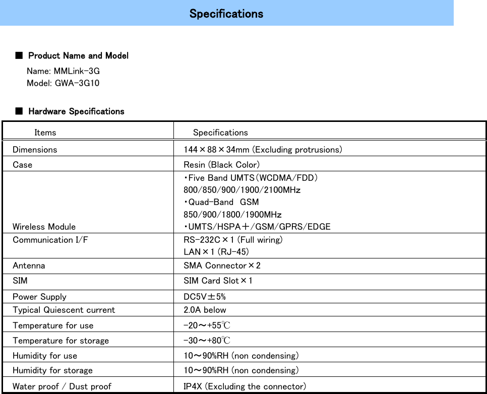
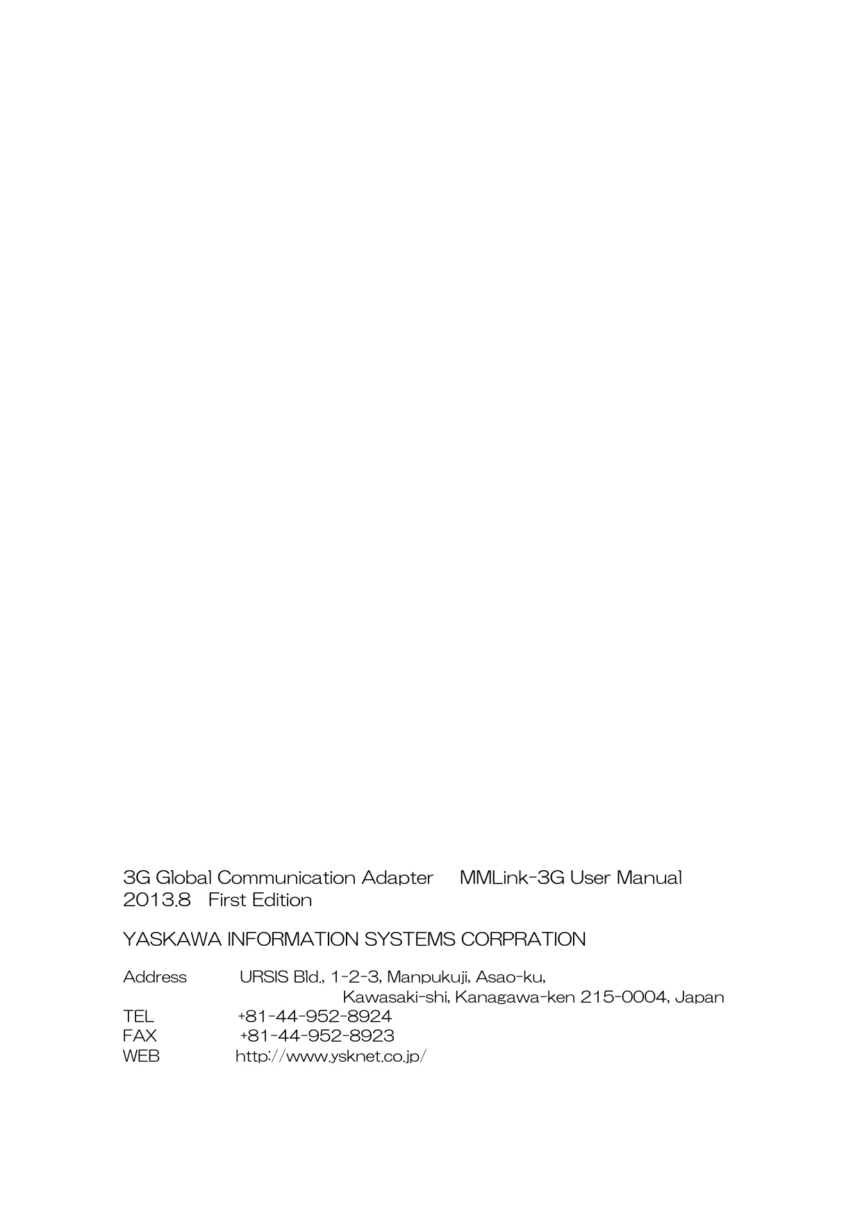
YE DIGITAL MMLINK-3G M2M 2G/3G Data Terminal User Manual

YASKAWA INFORMATION SYSTEMS Corporation M2M 2G/3G Data Terminal Users Manual

User Manual

                                 3G Global Communication Adapter  MMLink-3G   GWA-3G10  User Manual                       YASKAWA INFORMATION SYSTEMS CORPRATION
 II    Introduction   Introduction  MMLink-3G is Machine-to-Machine (M2M) communication adapter which provides UMTS wireless communication through the 3G cellular networks by using the onboard LAN interface.  Read this manual carefully before using MMLink-3G.    Precaution    Important Safety Information  This product is not intended for use in the following circumstances ・ Area(s) where radio transmission equipment (such as cell phone) are not permitted. ・ Hospitals, health care facilities and area(s) where cell phones are restricted by law. ・ Gas stations, fuel storage and places where chemical are stored. ・ Chemical plants or places with potential explosion hazard. ・ Any metal surface that may weaken the radio signal level. ・ The appliance is intended to be installed in restricted access location. Only service person or authorized person is allowed to access.
 III       INTRODUCTION ................................................................................................................................... II PRECAUTION ........................................................................................................................................ II BEFORE USING ..................................................................................................................................... 1 NAME OF EACH PARTS ............................................................................................................................... 1 STATUS INDICATION LEDS ........................................................................................................................ 2 RS-232C CONNECTOR ............................................................................................................................... 3 LAN INTERFACE ....................................................................................................................................... 3 ANTENNA CONNECTOR (SMA) ................................................................................................................... 4 POWER SUPPLY CONNECTOR (DC) ............................................................................................................. 4 BASIC OPERATIONS ............................................................................................................................. 5 CONNECTING THE ANTENNA AND CABLES ................................................................................................... 5 SWITCHING ON THE ADAPTER .................................................................................................................... 6 SWITCHING OFF THE ADAPTER ................................................................................................................... 6 PACKET COMMUNICATIONS ........................................................................................................................ 6 FEES ......................................................................................................................................................... 6 INSTALLATION ........................................................................................................................................... 7 FEATURES .............................................................................................................................................. 8 SUMMARY OF FEATURES ............................................................................................................................ 8 SIMPLE ROUTER (STATIC NAT) ................................................................................................................. 9 SETTINGS FOR THE SIMPLE ROUTER  (STATIC NAT) ................................................................................ 10 HOW TO USE THE SIMPLE LOCATION INFORMATION ACQUISITION COMMAND .......................................... 11 SMS AUTO CONNECTION ........................................................................................................................ 13 REMOTE DIAGNOSIS ................................................................................................................................ 13 FAIL-SAFE ............................................................................................................................................... 13 SPECIFICATIONS ...................................................................................................................................... 14      List of Content
     Before Using    Name of Each Parts   The following are the parts of this adapter.       Status Indication LEDs Antenna Connector (for connection) Power Supply Connector LAN Interface RS-232C Connector Back Label Power Switch SIM Card Cover Front Label Screw Hole Antenna Connector (for GPS)
     Status Indication LEDs  Status Indication LEDs can indicate the status of this adapter.     Name Color Description PWR  GREEN  Light when power is on. ANT ORANGE/ GREEN/ RED  Indicate the received signal level.   Signal status: Bad Off  Signal status: Poor Light on with red color  Signal status: Average Light on with orange color  Signal status: Good Light on with green color  STS ORANGE/ GREEN/ RED  Indicate the running status of this adapter. (Note)   Idle Off   Initializing Blink with green color  Information 1 Light on with orange color  Information 2 Light on with red color     DATA  GREEN  Indicate the communication status between this adapter and the wireless network.  Not communicating    Off Communicating       On  CD/RI  GREEN  Indicate the CD signal statue.  Wireless network disconnected    OFF Wireless network connecting       On Wireless network connected      On        Note:  About the information display of STS LED          Please contact the Customer Support Services when information 1 or information 2 is ON.     Information 1 : probably hardware failure.     Information 2 : probably SIM card is unreadable.
     RS-232C Connector   Pin Assignments                    LAN Interface    Pin Assignments                                Note:     MDI/X auto-cross/straight cable support. D-sub Connector PIN Assignments Pin No.  Signal  Pin No.  Signal 1  DCD  6  DSR 2  RxD  7  RTS 3  TxD  8  CTS 4  DTR  9  RI 5  GND  ー     RJ-45 Connector Pin Assignments Pin No.  Signal 1  Tx+ 2  Tx- 3  Rx+ 4  - 5  - 6  Rx- 7  - 8  -
     Antenna Connector (SMA)   Pin Assignments               Power Supply Connector (DC)    Pin Assignments                  GND Signal
     Basic Operations   Connecting the antenna and cables   Before using this adapter please do the following preparations.  Step 1. Attach the antenna to the antenna connector    Use the antennas that attached to this adapter. (Note 1)   Ensure that no excessive force is applied to the antenna connector.  Step 2. Ensure that the equipment and this adapter is powered off.   Step 3. Connect the power supply to the power connector  Use the power supply that attached to this adapter. (Note 2)   Step 4. Connect the equipment to this adapter.    Connect a LAN cable to this adapter’s LAN connector.    Note: 1. Please contact the Customer Support Services to obtain the information about recommended antennas by the manufactuer.  2. Please contact the Customer Support Services to obtain the information about recommended power supply (AC adapter) by the manufactuer.
        Switching on the Adapter   Turn on the Power Switch on the side of this adapter.  It takes about 30-60 seconds until it is ready to communicate after switched on. STS LED will keep blinking with green color while initializing, and will be turned off once  initialization is normally completed. Wait at least 5 seconds between powering off and on.       When performing packet communications, check the signal level on the ANT LED.    Switching off the Adapter   Turn off the Power Switch on the side of this adapter.      Check if the PWR LED is off.     It takes 3-5 seconds to shut down after turning off the Power Switch.    Packet Communications   ■ This adapter is available in the UMTS worldwide coverage.  ■ High-speed packet communications. DL: at maximum. 14.4 Mbps UL: at maximum. 5.76 Mbps  The line speed may be affected by communication environment and the contract with a carrier.    Fees   ■ Terms and packet communications services, contract fees, monthly fees, communication fees will be charged depending on the amount of data sent and received. For more information please contact Customer Support Services.  ■ If you are using Internet access services, your internet service provider will charge you for the service fee. For fee details, please contact your provider for help.  ■  Subscribing to dedicated lines will require a fee depending on connection fees and options contracts. For fee details, please contact your provider for help.
     Installation   ■Installation Dimensions (Back Case)      Dimension of screw hole: M3  (Effective screw length: 4mm)
      Features   Summary of Features  The following is a summary of the features.  Feature  Description  Simple Router (Static NAT)  IP packets received from equipment connected to this adapter can be transmitted to the WAN by IP address transforming.  Simple Location   Information Acquisition  Location information can be acquired using a simple command by TCP / IP communications from the LAN interface of this adapter.  SMS Auto Connection  This adapter automatically connects to the wireless network after receiving an SMS message.  Remote Diagnosis  The network connectivity of this adapter can be checked.  Fail-Safe  This adapter can detect communication failures and recover automatically.
     Simple Router (Static NAT)   This adapter can communicate with the WAN using TCP/IP packets by connecting your equipment to it via LAN.  The following diagram shows the operations of the equipment connected to MMLink-3G.                                    Equipment Network(Operator) Local IP Global IP Data Communication Unconnection State Connection Start Connecting State  Disconnection Start Unconnection State LAN Obtain the MAC address by ARP IP Packet① note  Received local IP packets will  be discarded until the global  IP address has been acquired. Dial-up PPP Connection Acquire a global IP address successfully IP packet communication  Static NAT(Address Translation) Disconnection request from the network PPP  disconnection Hung up MMLink-3G
      Settings for the Simple Router  (Static NAT)  Your equipment needs be equipped with the protocols below.   7    Application Layer 6    Presentation Layer 5    Session Layer 4 TCP Transport Layer 3 IP Network Layer 2 Ethernet Data Link Layer 1  Physical Layer   ■ The TCP/IP settings of this adapter  IP Address  192.168.0.133 Subnet Mask  255.255.255.0   The TCP/IP settings of equipment  IP Address  192.168.0.100 Subnet Mask  255.255.255.0 Default Gateway  192.168.0.133   ■ Static address translation     Network Environment Equipment This Adapter Server IP Address 192.168.0.100 Local IP Address 192.168.0.133 Global IP Address 10.129.100.1 IP Address 172.16.100.2 TCP/IP protocol is required.
     How to Use the Simple Location Information Acquisition Command  You can get the location information via a command by using a specific TCP/IP port.  Note: Location information obtained by this command is based on cellular system, so it’s  different  from  the  GPS positioning.  ■ The setting of the service port Please use the following dedicated TCP/IP port to perform the Simple Location Information Acquisition Command.  Port No. 777      Simple Location Information Acquisition Command                       The format of the location information.   <ASCII String>  3G,262,03,9C57, 7E7D68B,20             TCP/IP Head GETPOS (ASCII) CR+LF TCP/IP Head  OK (ASCII) CR+LF TCP/IP Head Location Information CR+LF TCP/IP Head :END (ASCII) CR+LF Equipment This Adapter Mobile Country Code(MCC) : decimal digits  Mobile Network Code(MNC) : decimal digits  Received Signal Level(RSSI) : decimal digits  Cell Identifier(CellID) : hexadecimal digits  Location Area Code(LAC) : hexadecimal digits  Access Technology
    The communication sequence is as follows: This adapter is a TCP Socket Server, and the equipment is a TCP Socket Client. They need to connect or disconnect using TCP/IP.  The simple router feature is enabled while the service port is using, so you can acquire the location information while normal data communication. Equipment (Client) This Adapter (Server) TCP/IP Connection Wait TCP Connection TCP/IP disconnection Location Information Acquisition Command Response (Location Information) Receive the Command   Get Location Information Make the Response
       SMS Auto Connection  This adapter supports automatic connection to the wireless network by an SMS message.  When this adapter receives an SMS, the following processes will be performed. ■ In the case, This adapter has not been connected to the wireless network Automatically connect to the wireless network. The TCP/IP communication will be ready once the connection is successful.  ■ In the case, This adapter has been connected to the wireless network already Wireless network connection will be kept.     Remote Diagnosis    This adapter supports network connectivity detection by an ICMP packet.  By sending an ICMP packet as below, you can verify whether this adapter is connected to the wireless network.  ■ When received a ICMP 13 from the wireless network, this adapter will respond by sending ICMP 14,    Note:  ICMP type 13 packets are not routed to the equipment that is connected to this adapter. This feature is only for checking the connection state of the adapter, so the data in the packet is meaningless.   Fail-Safe  This adapter communicates with wireless network by the wireless module equipped. In some cases, the wireless module cannot continue communication normally due to poor network conditions (such as out of service, a weak signal level, and  the base station design change and communication failure), combined with  functions of the wireless module itself. This adapter can detect such communication failures and recover automatically.  When failures were detected, this adapter will reset itself automatically, so the communication between this adapter and the equipment will temporary stop.  Although frequency of the automatic recovery is rare, please implement the following fail-safe features to your equipment in principle.  ■ Reconnect this adapter if the LAN interface is disconnected,   ■ If your system does not recover by a normal retry procedure, please reset this adapter.
     Specifications   ■ Product Name and Model   Name: MMLink-3G   Model: GWA-3G10  ■ Hardware Specifications   Items  Specifications Dimensions  144×88×34mm (Excluding protrusions) Case Resin (Black Color) Wireless Module ・Five Band UMTS(WCDMA/FDD) 800/850/900/1900/2100MHz ・Quad-Band GSM 850/900/1800/1900MHz ・UMTS/HSPA+/GSM/GPRS/EDGE Communication I/F  RS-232C×1 (Full wiring) LAN×1 (RJ-45) Antenna  SMA Connector×2 SIM SIM Card Slot×1 Power Supply DC5V±5% Typical Quiescent current  2.0A below Temperature for use  -20~+55℃ Temperature for storage  -30~+80℃ Humidity for use  10~90%RH (non condensing) Humidity for storage  10~90%RH (non condensing) Water proof / Dust proof  IP4X (Excluding the connector)
    Compliance Statements: This device complies with Part 15 of the FCC Rules. Operation is subject to the following two conditions:   (1) this device may not cause harmful interference, and   (2) this device must accept any interference received, including interference that may cause undesired operation.  Modifications not expressly approved by YASKAWA  could void the user’s authority to operate the equipment.  This equipment has been tested and found to comply with the limits for a Class B digital device, pursuant to Part 15 of the FCC Rules. These limits are designed to provide reasonable protection against harmful interference in a residential installation. This equipment generates, users and can radiate radio frequency energy and, if not installed and used in accordance with the instructions, may cause harmful interference to radio communications. However, there is no guarantee that interference will not occur in a particular installation. If this equipment does cause harmful interference to radio or television reception, which can be determined by turning the equipment off and on, the user is encouraged to try to correct the interference by one or more of the following measures: - Reorient or relocate the receiving antenna. - Increase the separation between the equipment and receiver. - Connect the equipment into an outlet on a circuit different from that to which the receiver is connected. - Consult the dealer or an experienced radio/TV technician for help.  Radiofrequency radiation exposure Information: This equipment complies with FCC radiation exposure limits set forth for an uncontrolled environment. This equipment should be installed and operated with minimum distance of 20 cm between the radiator and your body. This transmitter must not be co-located or operating in conjunction with any other antenna or transmitter.  CAN ICES-3 (B)/NMB-3(B)
                                              3G Global Communication Adapter   MMLink-3G User Manual 2013.8  First Edition  YASKAWA INFORMATION SYSTEMS CORPRATION  Address       URSIS Bld., 1-2-3, Manpukuji, Asao-ku,                                Kawasaki-shi, Kanagawa-ken 215-0004, Japan TEL           +81-44-952-8924 FAX           +81-44-952-8923 WEB          http://www.ysknet.co.jp/

Navigation menu