Wistron MS2133 MS2133 User Manual TMC110 en
Wistron Corporation MS2133 TMC110 en
UserManual.wiki
>
Wistron
>
MS2133 User Manual
>
Manual 3 of 3
Contents
1.
part 1 of 3
2.
part 2 of 3
3.
part 3 of 3
4.
Manual 1of 3
5.
Manual 2 of 3
6.
Manual 3 of 3
7.
2nd Revised manual
8.
2nd Rev Manual
Manual 3 of 3
Navigation menu
Upload a User Manual
Namespaces
Wiki Guide
HTML
PDF
Info
Views
User Manual
Discussion / Help
Navigation

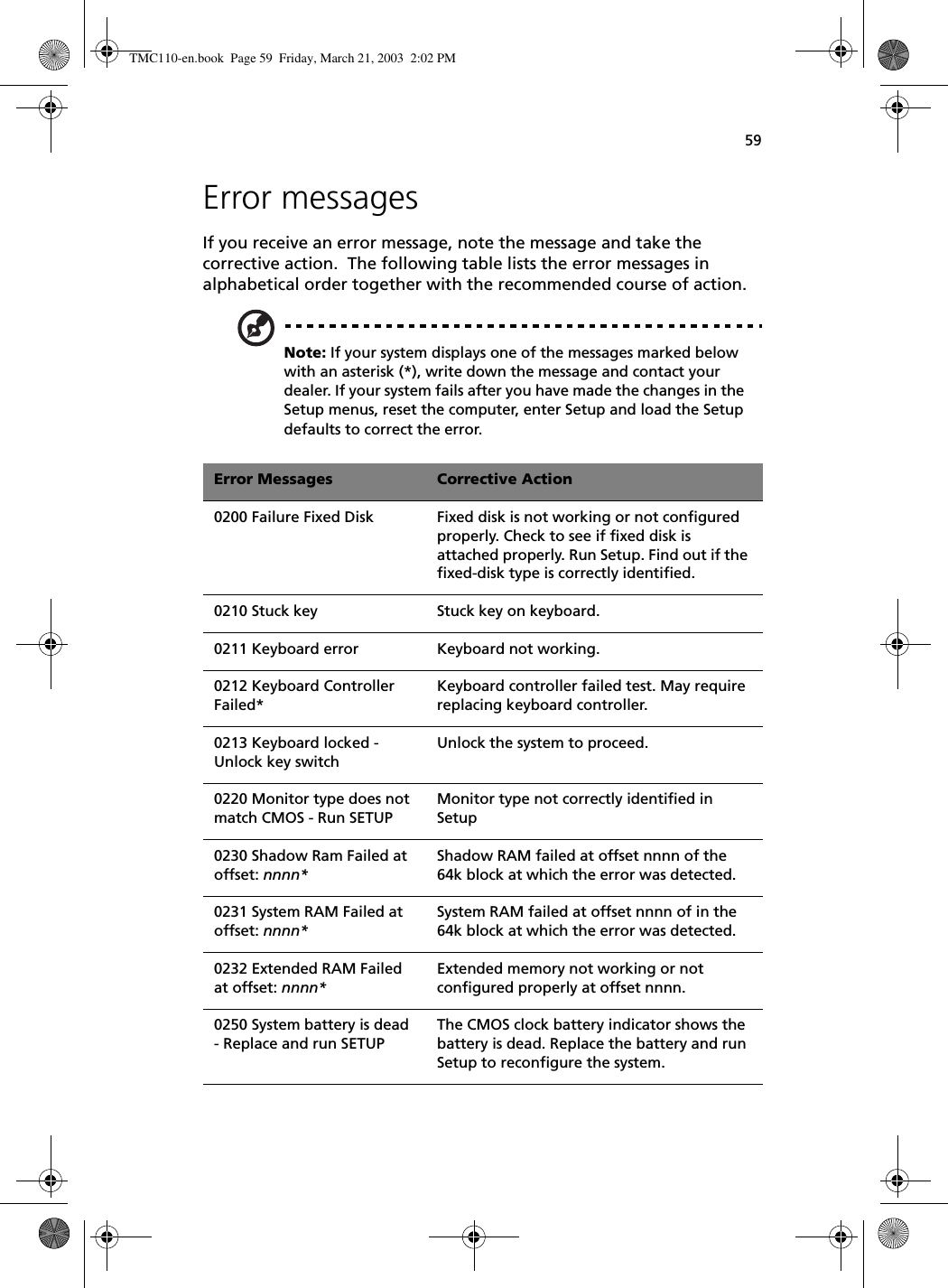
![Appendix B Notices74Notice: Canadian usersThis Class B digital apparatus meets all requirements of the Canadian Interference-Causing Equipment Regulations.Remarque à l’intention des utilisateurs canadiensCet appareil numérique de la classe B respected toutes les exigences du Règlement sur le matériel brouilleur du Canada.Modem noticesFCCThis equipment complies with Part 68 of the FCC rules. Located on the bottom side of the modem is a label that contains, among other information, the FCC Registration Number and Ringer Equivalence Number (REN) for this equipment. Upon request, you must provide this information to your telephone company.If your telephone equipment causes harm to the telephone network, the telephone company may discontinue your service temporarily. If possible, they will notify you in advance. But, if advance notice is not practical, you will be notified as soon as possible. You will also be informed of your right to file a complaint with the FCC.Your telephone company may make changes in its facilities, equipment, operations, or procedures that could affect the proper functioning of your equipment. If they do, you will be notified in advance to give you an opportunity to maintain uninterrupted telephone service.If this equipment should fail to operate properly, disconnect the equipment from the phone line to determine if it is causing the problem. If the problem is with the equipment, discontinue use and contact your dealer or vendor.TBR 21This equipment has been approved [Council Decision 98/482/EC - “TBR 21”] for pan-European single terminal connection to the Public Switched Telephone Network (PSTN). However, due to differences between the individual PSTNs provided in different countries, the approval does not, of itself, give an unconditional assurance of successful operation on every PSTN termination point. In the event of problems, you should contact your equipment supplier in the first instance.TMC110-en.book Page 74 Friday, March 21, 2003 2:02 PM](https://usermanual.wiki/Wistron/MS2133.Manual-3-of-3/User-Guide-358337-Page-34.png)
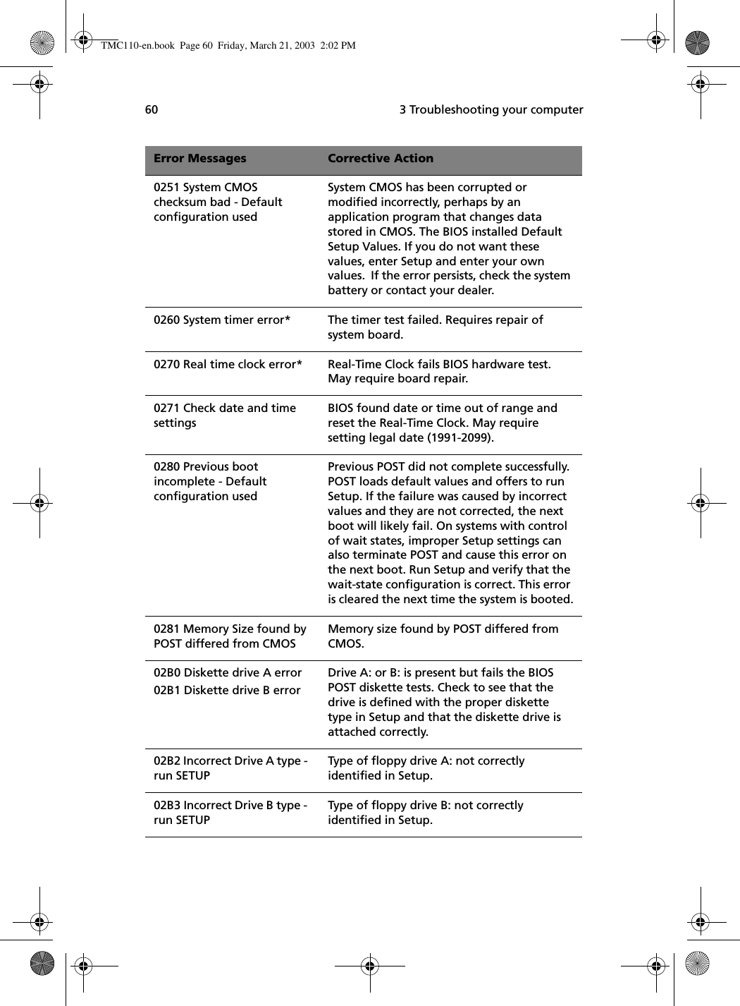
![DRAFT Wireless Regulatory and Safety Notice This guide provides all country specific regulatory notices and compliance information for your notebook computer, including wireless notices. Canada Canada Radio Frequency Interference Requirements The device is certified to the requirements of the RSS-210 for LELAN devices. The use of this device in a system operating either partially or completely outdoors may require the user to obtain a license for the system according to the Canadian regulations. For further information, contact your local Industry Canada office. This Class B digital apparatus complies with Canadian ICES-003, Issue 2, and RSS-210, Issue 4 (Dec. 2000). “To prevent radio interference to the licensed service, this device is intended to be operated indoors and away from windows to provide maximum shielding. Equipment (or its transmit antenna) that is installed outdoors is subject to licensing.” Cet appareil numérique de la classe B est conforme à la norme NMB-003, No. 2, et CNR-210, No. 4 (Dec. 2000). « Pour empêcher que cet appareil cause du brouillage au service faisant l'objet d'une licence, il doit être utilisé à l'intérieur et devrait être placé loin des fenêtres afin de fournir un écran de blindage maximal. Si le matériel (ou son antenne d'émission) est installé à l'extérieur, il doit faire l'objet d'une licence. » European Union (R&TTE) EU member states as of April 2003 are: Belgium, Denmark, Germany, Greece, Spain, France, Ireland, Italy, Luxembourg, the Netherlands, Austria, Portugal, Finland, Sweden, and the United Kingdom. European Regulatory and Compliance Information European Union CE Marking and Compliance Notices Products (including packaging and documentation) intended for sale within the European Union are marked with the Conformité Européene (CE) Marking, which indicates compliance with the applicable Directives and European standards and amendments identified below. This equipment also carries the Class 2 identifier. Declaration of Conformity (Dual-Band MiniPCI Adapter) [to be supplied] Product Descriptions: Intel® PRO/Wireless 2100A LAN 3B MiniPCI Adapter (model WM3B2100A) Intel Corporation declares that the equipment described in this document is in conformance with the essential requirements of the European Council Directives, standards, and other normative documents listed below: 73/23/EEC Safety of the User (article 3.1.a) 89/336/EEC Electromagnetic Compatibility (article 3.1.b) 1999/5/EC (R&TTE) Radio and Telecommunications Terminal Equipment Directive (Following annex IV for model WM3B2100A)](https://usermanual.wiki/Wistron/MS2133.Manual-3-of-3/User-Guide-358337-Page-41.png)
![EN 60950 1992 2nd Edition (A1 – A4, A11) Safety of Information Technology Equipment, Including Electrical Business Equipment EN 300 328 V1.4.1 (April 2003) Electromagnetic compatibility and Radio spectrum Matters (ERM); Wideband Transmission system; data transmission equipment operating in the 2.4GHz ISM band and using spread spectrum modulation techniques; Part 1: Technical characteristics and test conditions; Part 2; Harmonized EN covering essential requirements under article 3.2 of the R&TTE Directive. EN 301 489-1, Aug. 2000; EN 301489-17, Sept. 2000 – Electromagnetic compatibility and radio spectrum matters (ERM); electromagnetic compatibility (EMC) standard for radio equipment and services: Part 1: Common technical requirements; Part 17: Specific conditions for Wideband Data and HIPERLAN equipment Draft EN 301 893 v1.2.1, (2002-07) – Broadband Radio Access Networks (BRAN); 5 GHZ high performance RLAN; Harmonized EN covering essential requirements of Article 3.2 of the R&TTE Directive. IDA-TS-SSS, Following FCC OET bulletin 65 supplement C guidelines – Specific Absorption Rate (SAR) evaluating radio equipment for human exposure to radiofrequency electromagnetic fields. Warning: See 802.11a and 802.11b restrictions and guidelines for specific EU countries, or regions within countries, under the heading “European Economic Area Restrictions” below. Translated Statements of Compliance [English] This product follows the provisions of the European Directive 1999/5/EC. [Danish] Dette produkt er i overensstemmelse med det europæiske direktiv 1999/5/EC [Dutch] Dit product is in navolging van de bepalingen van Europees Directief 1999/5/EC. [Finnish] Tämä tuote noudattaa EU-direktiivin 1999/5/EC määräyksiä. [French] Ce produit est conforme aux exigences de la Directive Européenne 1999/5/EC. [German] Dieses Produkt entspricht den Bestimmungen der Europäischen Richtlinie 1999/5/EC [Greek] Το προϊόν αυτό πληροί τις προβλέψεις της Ευρωπαϊκής Οδηγίας 1999/5/ΕC. [Icelandic] Þessi vara stenst reglugerð Evrópska Efnahags Bandalagsins númer 1999/5/EC [Italian] Questo prodotto è conforme alla Direttiva Europea 1999/5/EC. [Norwegian] Dette produktet er i henhold til bestemmelsene i det europeiske direktivet 1999/5/EC. [Portuguese] Este produto cumpre com as normas da Diretiva Européia 1999/5/EC. [Spanish] Este producto cumple con las normas del Directivo Europeo 1999/5/EC. Page 2 of 8](https://usermanual.wiki/Wistron/MS2133.Manual-3-of-3/User-Guide-358337-Page-42.png)
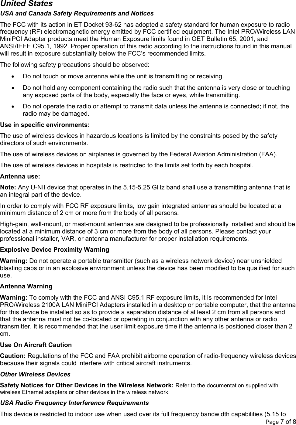
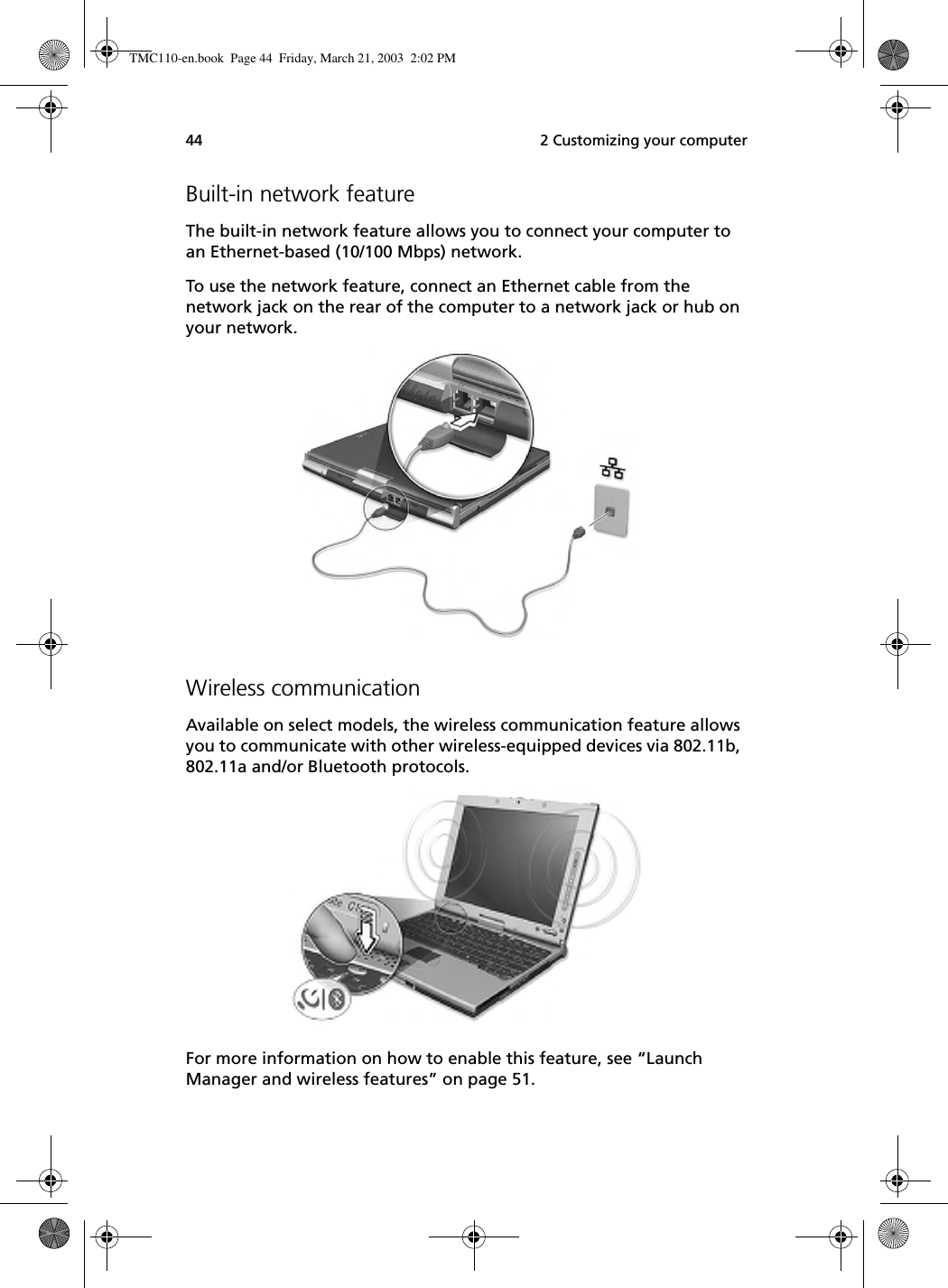
![[Swedish] Denna produkt har tillverkats i enlighet med EG-direktiv 1999/5/EC. European Economic Area Restrictions Note on Local Restrictions on 802.11a and 802.11b Radio Usage Caution: Due to the fact that the frequencies used by 802.11a and 802.11b wireless LAN devices may not yet be harmonized in all countries, 802.11a and 802.11b products are designed for use only in specific countries, and are not allowed to be operated in countries other than those of designated use. As a user of these products, you are responsible for ensuring that the products are used only in the countries for which they were intended and for verifying that they are configured with the correct selection of frequency and channel for the country of use. The device transmit power control (TPC) interface is part of the Intel(R) PROSet software. Operational restrictions for Equivalent Isotropic Radiated Power (EIRP) are provided by the system manufacturer. Any deviation from the permissible power and frequency settings for the country of use is an infringement of national law and may be punished as such. The European variant is intended for use throughout the European Economic Area. However, authorization for use is restricted as follows: Permissible Frequencies 802.11b Permissible Frequencies For all EU members except France, the allowed frequencies for 802.11b are 2400-2483.5 Mhz. See additional restrictions below for France under the heading Additional 802.11a and 802.11b Restrictions. 802.11a Permissible Frequencies Intel PRO/Wireless 2100A LAN MiniPCI Adapters in 5 GHz mode support passive scanning for selection of channels. This means that the adapter obtains its channel settings from the access point to which it is connected. These values cannot be set on the adapter itself. In order to comply with local regulations, adapters must only be used with access points configured for the legal channels in the country of use. Country Permissible frequencies Austria 5.15 - 5.25 GHz Belgium 5.15 – 5.35 GHz Denmark 5.15 - 5.25 GHz Finland 5.15 – 5.35 GHz France 5.15 – 5.25 GHz Germany 5.15 – 5.25 GHz Iceland 5.15 – 5.25 GHz Ireland 5.15 – 5.35 GHz Italy 5.15 – 5.25 GHz Luxembourg 5.15 – 5.35 GHz Netherlands+ 5.15 – 5.35 GHz Norway 5.15 – 5.25 GHz Portugal 5.15 – 5.25 GHz Sweden+ 5.15 –5.25 GHz Switzerland 5.15 – 5.25 GHz United Kingdom 5.15 – 5.35 GHz +Subject to verification. Page 3 of 8](https://usermanual.wiki/Wistron/MS2133.Manual-3-of-3/User-Guide-358337-Page-43.png)