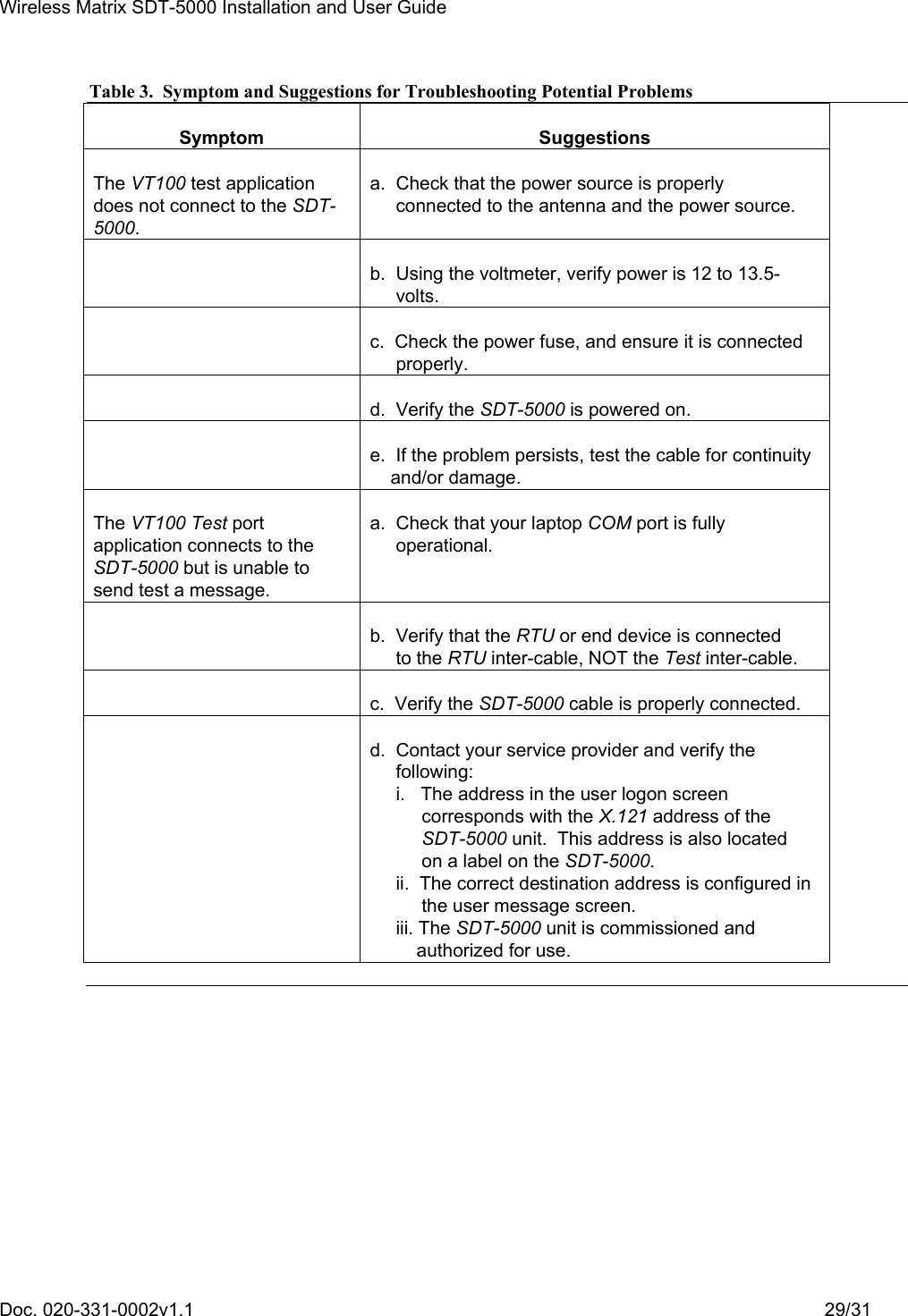
Wireless Matrix SDT5 Satellite Earth Station Equipment User Manual users manual
Wireless Matrix Corporation Satellite Earth Station Equipment users manual
UserManual.wiki
>
Wireless Matrix
>
SDT5 User Manual
users manual
Navigation menu
Upload a User Manual
Namespaces
Wiki Guide
HTML
PDF
Info
Views
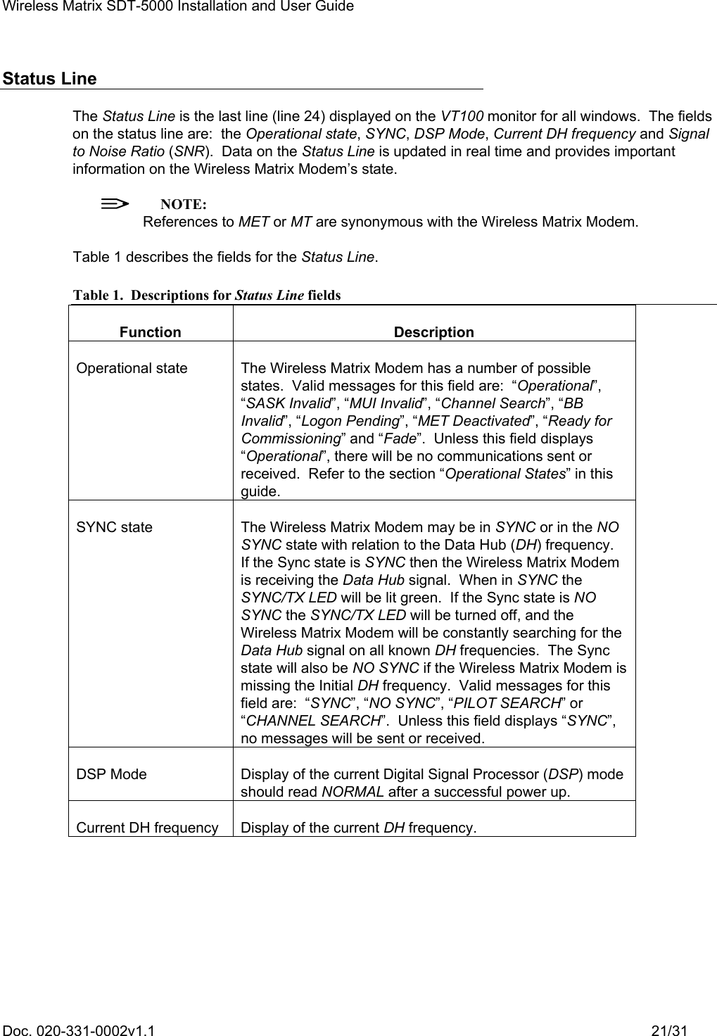
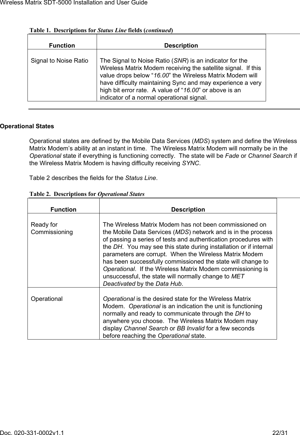
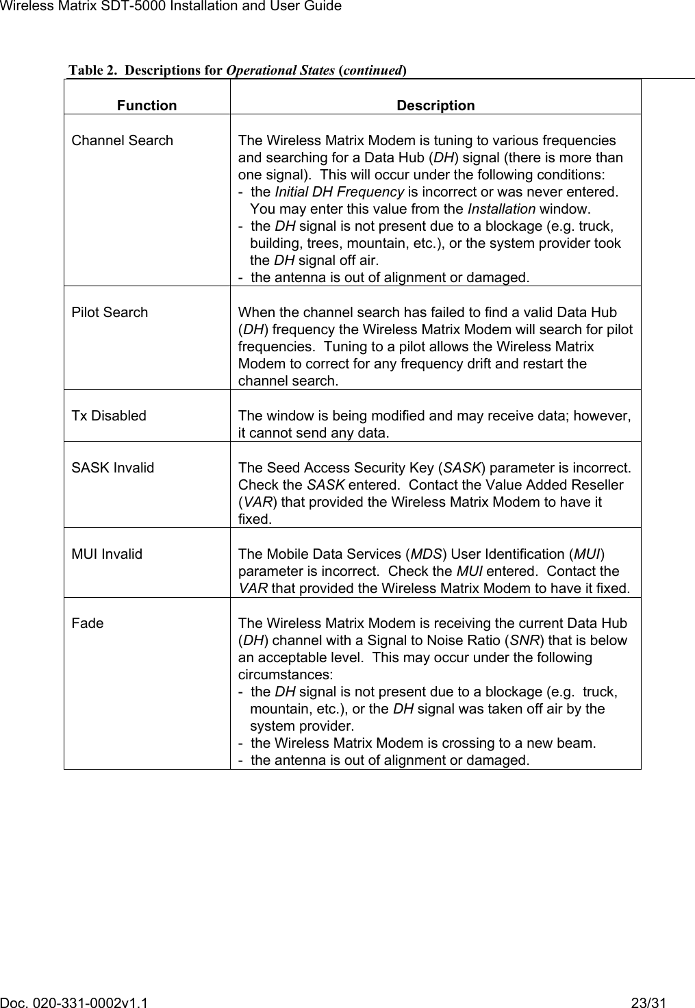
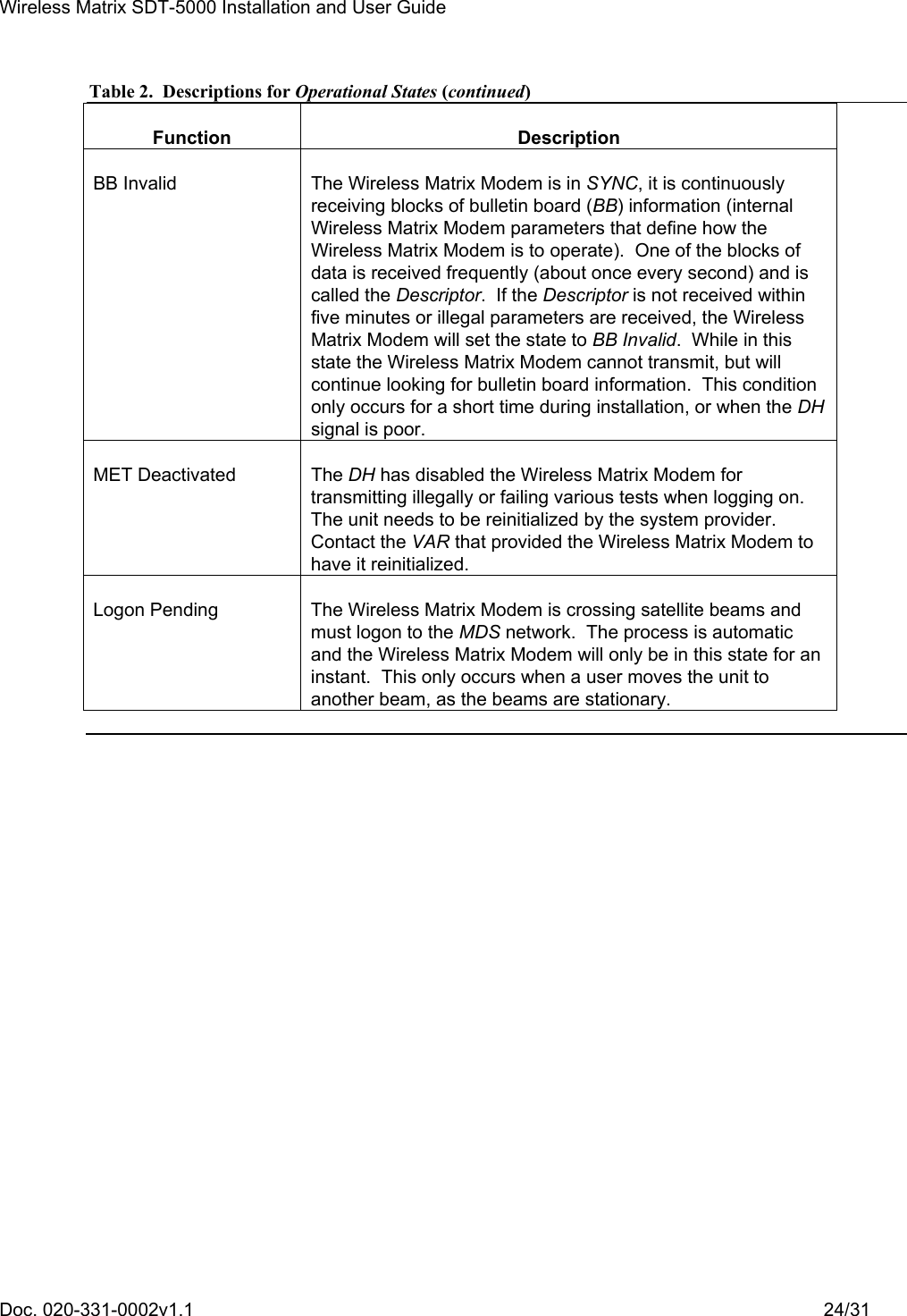
User Manual
Discussion / Help
Navigation