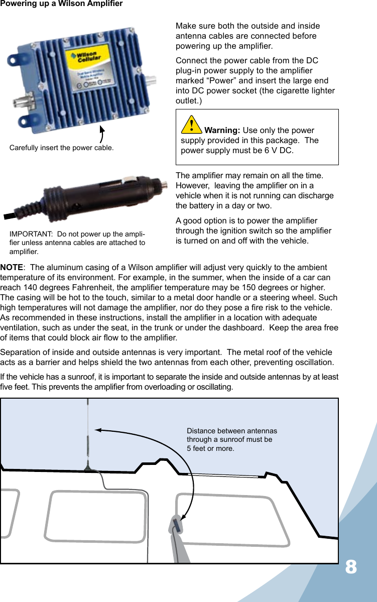
Wilson Electronics 8012SM WIRELESS CELL PHONE AMPLIFIER User Manual MOBILE INSTALLATION GUIDE
Wilson Electronics, LLC WIRELESS CELL PHONE AMPLIFIER MOBILE INSTALLATION GUIDE
Contents
- 1. Users Manual
- 2. MOBILE INSTALLATION GUIDE
- 3. INSTALLATION GUIDE
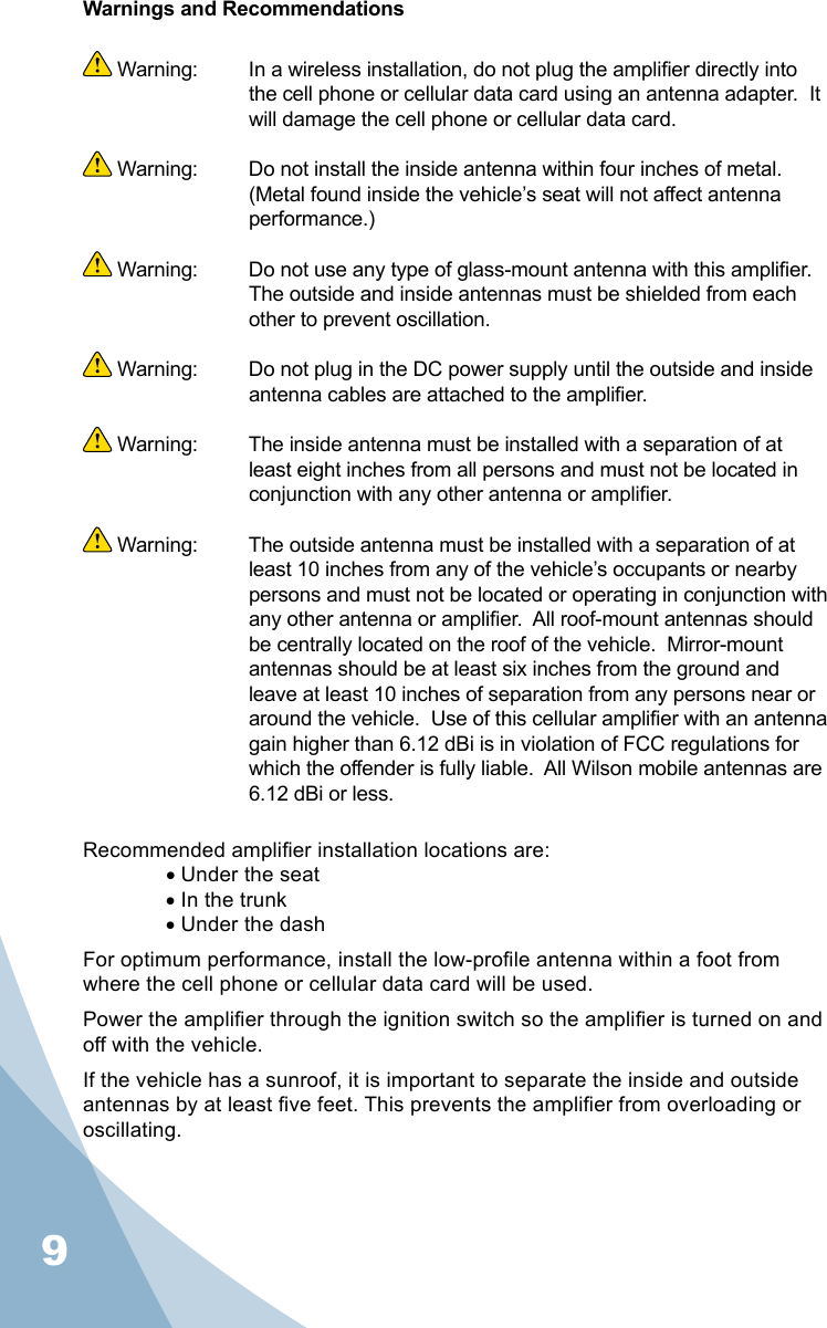
MOBILE INSTALLATION GUIDE