Westell PSA91080-UHF Bi-Directional Amplifier User Manual Part 2
Westell, Inc. Bi-Directional Amplifier Part 2
UserManual.wiki
>
Westell
>
PSA91080-UHF User Manual
>
User Manual_Part 2
Contents
1.
User Manual_Part 1
2.
User Manual_Part 2
User Manual_Part 2
Navigation menu
Upload a User Manual
Namespaces
Wiki Guide
HTML
PDF
Info
Views
User Manual
Discussion / Help
Navigation
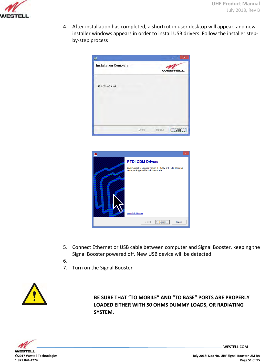
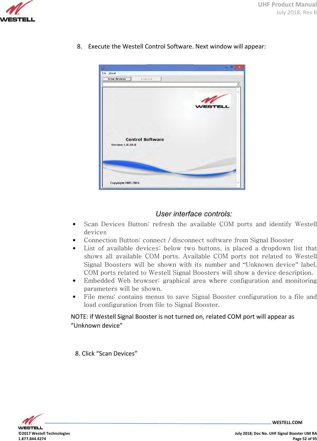
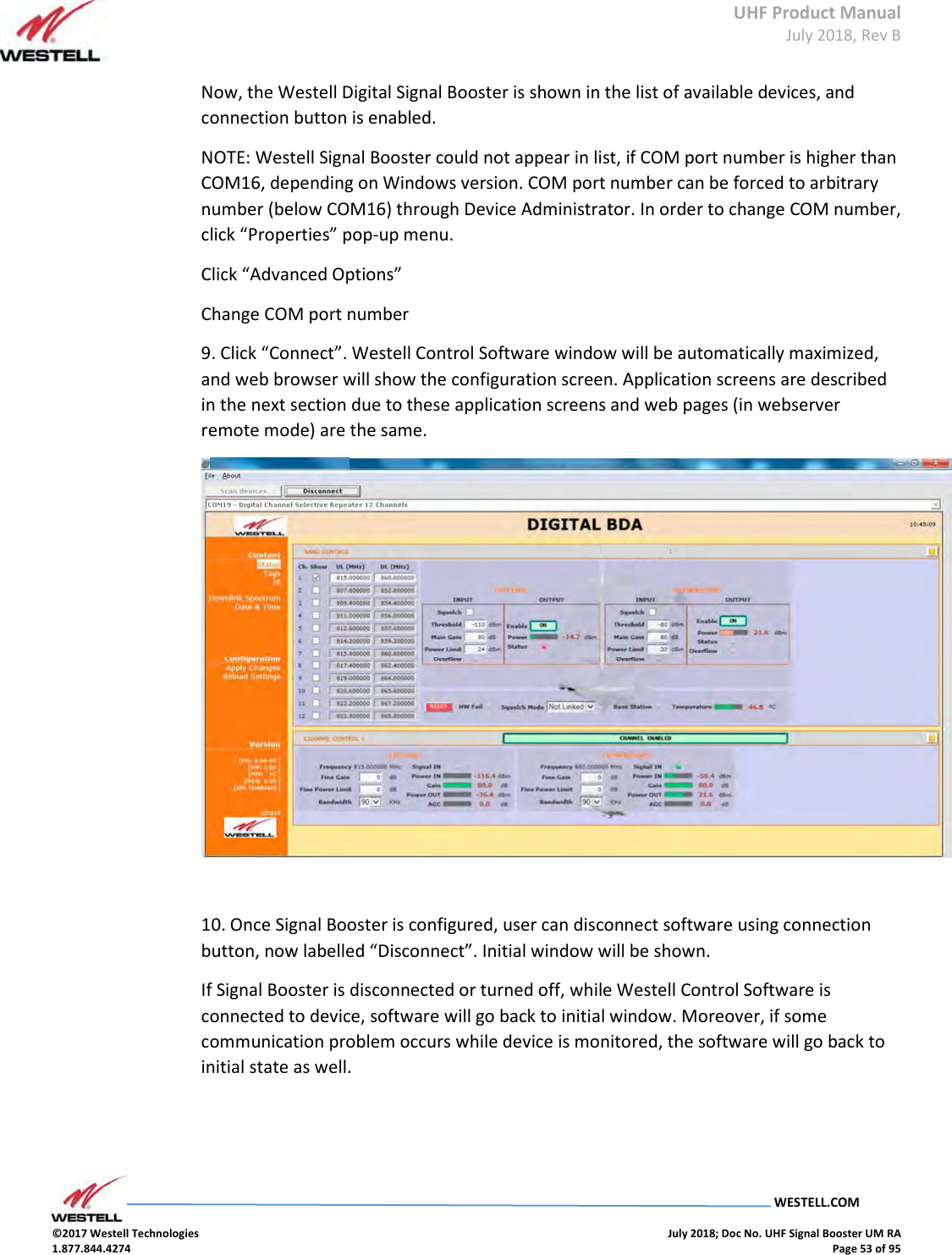
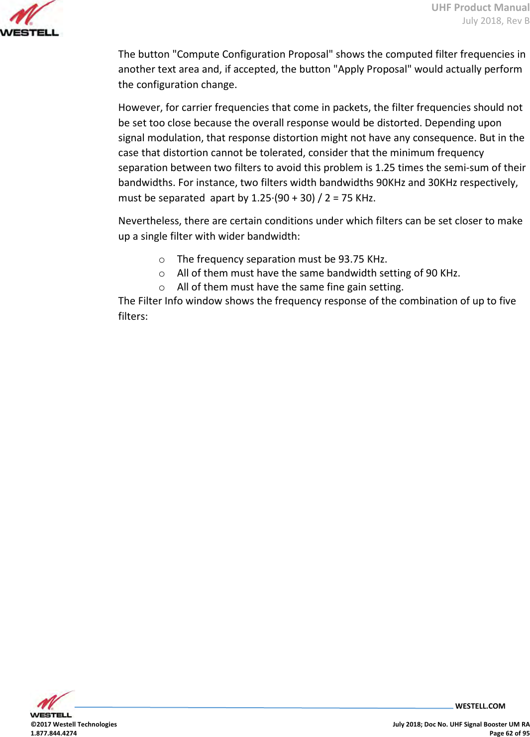
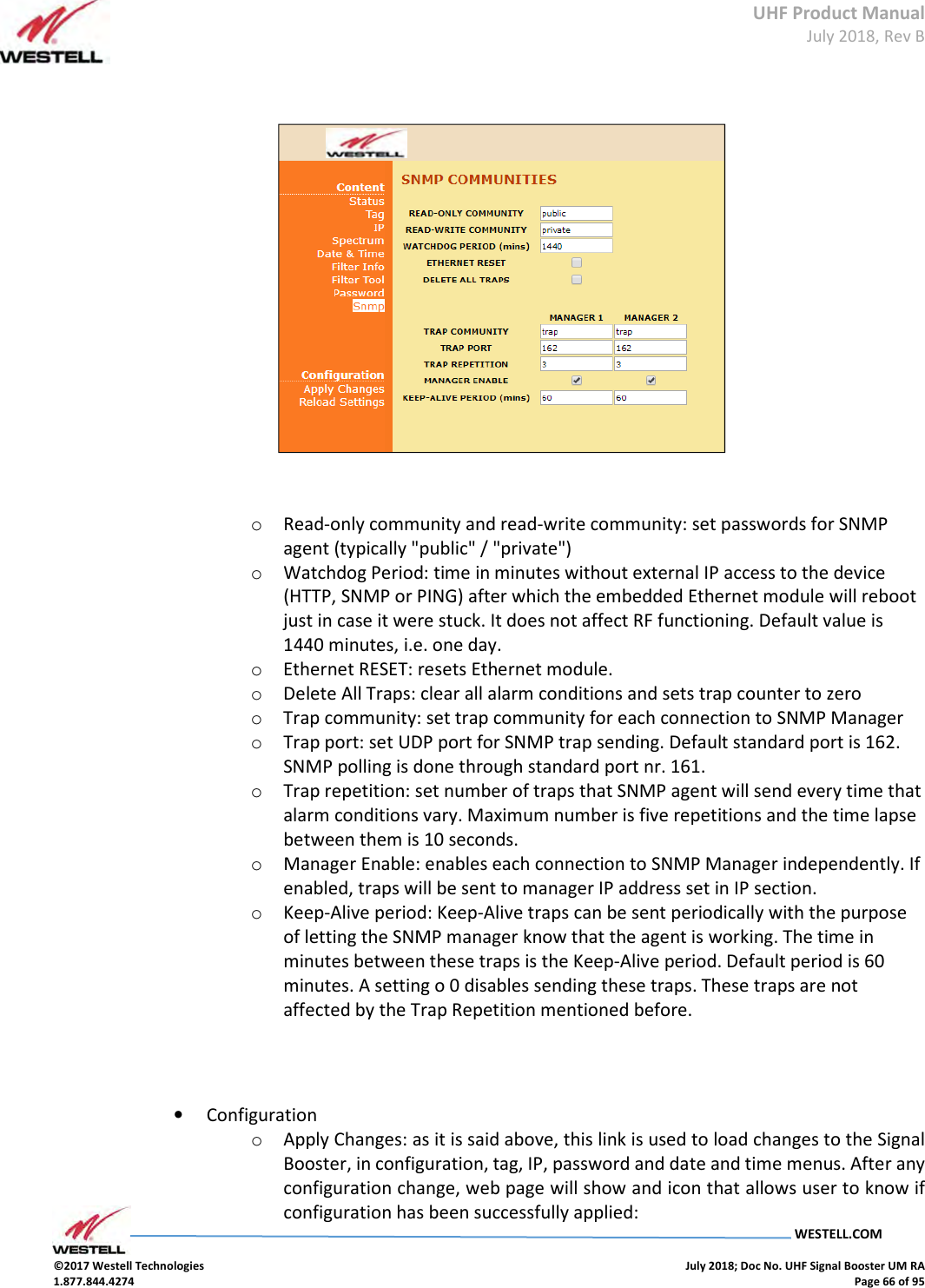
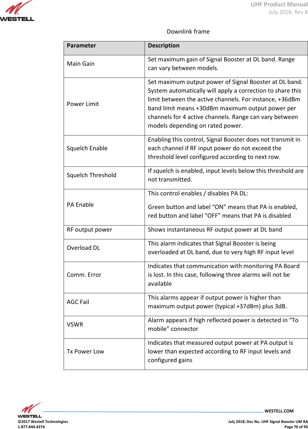
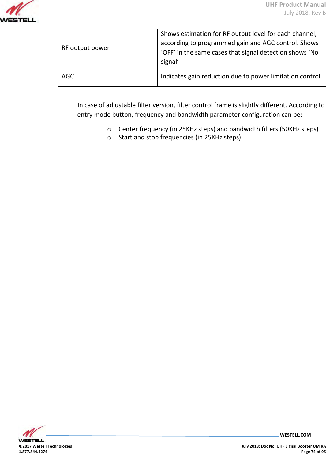
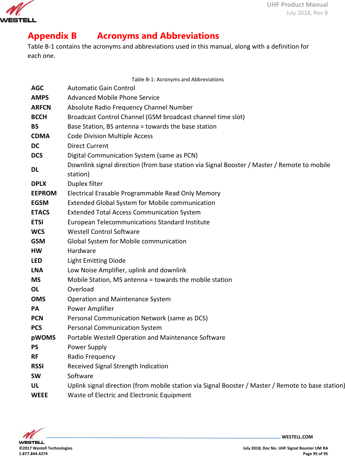
![UHF Product Manual July 2018, Rev B WESTELL.COM ©2017 Westell Technologies July 2018; Doc No. UHF Signal Booster UM RA 1.877.844.4274 Page 78 of 95 13131313 SNMP AgentSNMP AgentSNMP AgentSNMP Agent Westell Signal Booster includes a SNMPv1 agent that allows user to supervise the device by means of 'SET' and 'GET' type commands and, asynchronous traps to notify alarm conditions can be sent. The device is intended to be monitored by a polling NMS but it can send traps to a NMS or Trap Receiver if enabled. Westell can provide a NMS system upon request. The following sections will show the user configurable, relevant information that can be read via SNMP from the device. The tables will describe these values in order to explain how the information has to be read and interpreted. MIB Description The associated MIB document is WESTELL-BDA-SYSTEMv13-MIB.mib. The Westell MIB is divided into blocks. Each block describes the characteristics and values of a specific element but not all elements are implemented in this agent. Each MIB block is divided in two segments, named 1T and 2T. Segment 1T contains the information that is fixed & read only. Segment 2T has the information that can vary over time, regardless of it being read/only or read/write. The following sections will show the user configurable, relevant information that can be read via SNMP from the device. Manager This is a table with 2 consecutive elements, one for each NMS. No checking is done of the validity of the information stored in the table, so extra care must be taken by the user. SNMP Managers table Field Name OID Description Type Man2TAddress[0] 1.3.6.1.4.1.26355.2.50.3.2.1.2.0 First NMS Address R/W Man2TAddress[1] 1.3.6.1.4.1.26355.2.50.3.2.1.2.1 Second NMS Address R/W](https://usermanual.wiki/Westell/PSA91080-UHF.User-Manual-Part-2/User-Guide-4027077-Page-28.png)
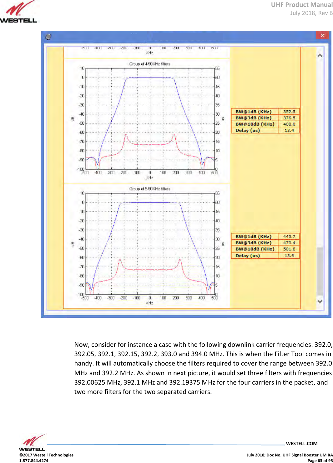
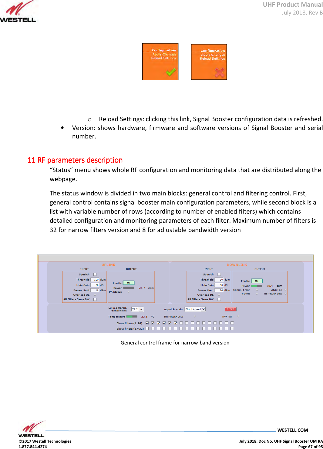
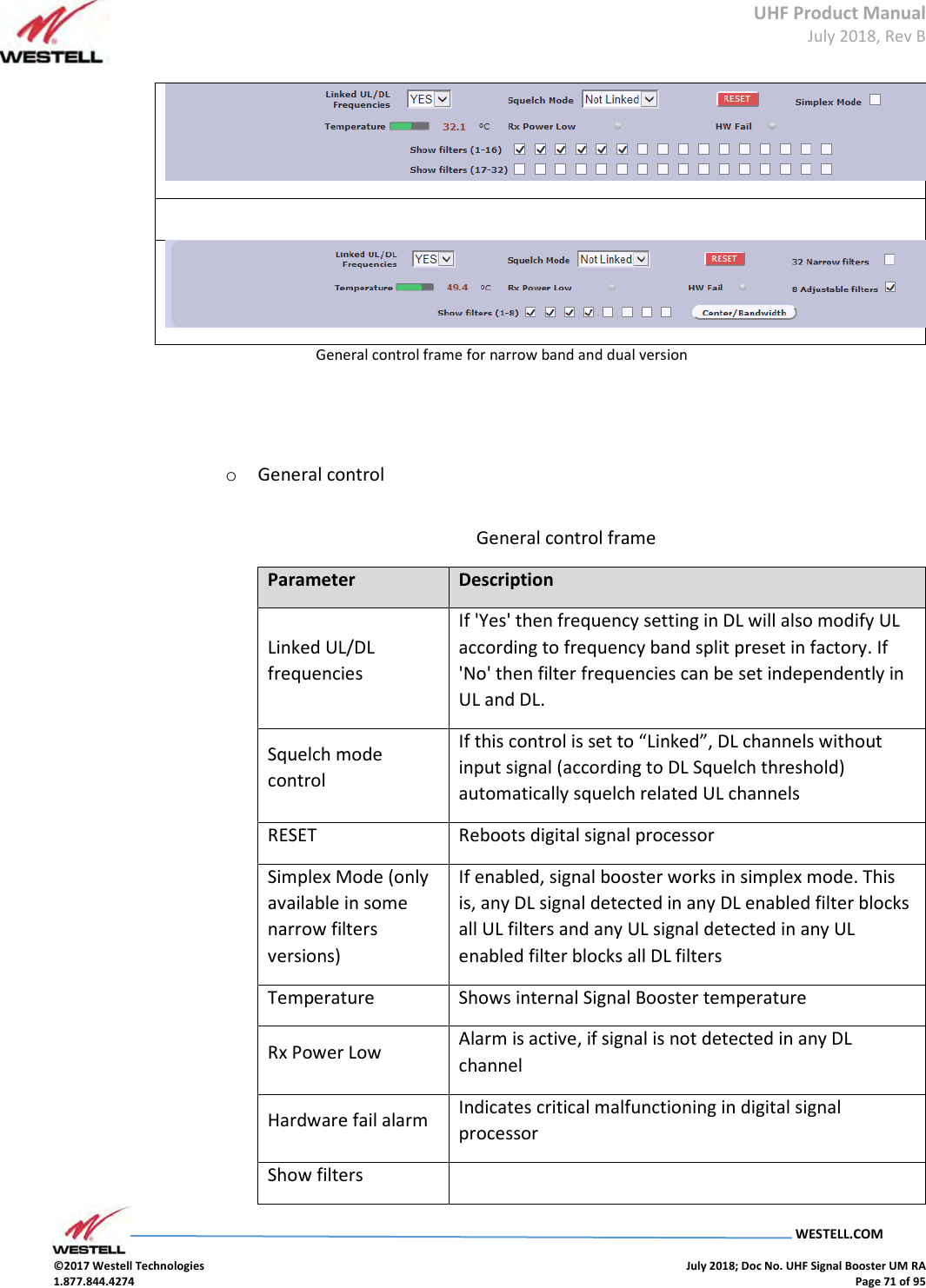
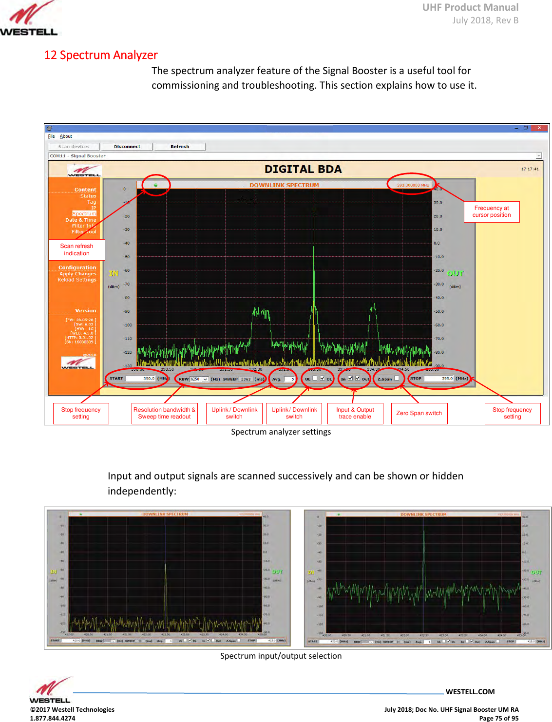
![UHF Product Manual July 2018, Rev B WESTELL.COM ©2017 Westell Technologies July 2018; Doc No. UHF Signal Booster UM RA 1.877.844.4274 Page 79 of 95 Man2TPort[0] 1.3.6.1.4.1.26355.2.50.3.2.1.3.0 First NMS Port where to send traps R/W Man2TPort[1] 1.3.6.1.4.1.26355.2.50.3.2.1.3.1 Second NMS Port where to send traps R/W Man2TEnable[0] 1.3.6.1.4.1.26355.2.50.3.2.1.5.0 First NMS. 1= Enabled, 2=Disabled R/W Man2TEnable[1] 1.3.6.1.4.1.26355.2.50.3.2.1.5.1 Second NMS. 1= Enabled, 2=Disabled. R/W Man2TAliveNotificationPeriod[0] 1.3.6.1.4.1.26355.2.50.3.2.1.6.0 First NMS. If enabled in Man2TEnable, defined time between keep-alive traps. R/W Man2TAliveNotificationPeriod[1] 1.3.6.1.4.1.26355.2.50.3.2.1.6.1 Second NMS. If enabled in Man2TEnable, defined time between keep-alive traps. R/W The following MIB tree representation shows this table: SNMP Managers table](https://usermanual.wiki/Westell/PSA91080-UHF.User-Manual-Part-2/User-Guide-4027077-Page-29.png)
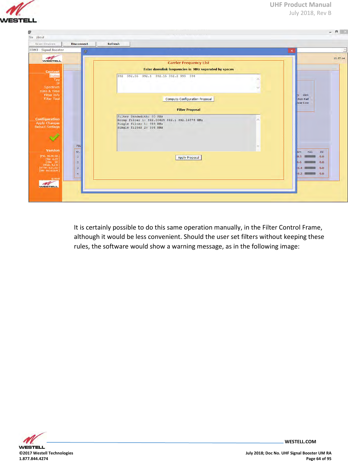
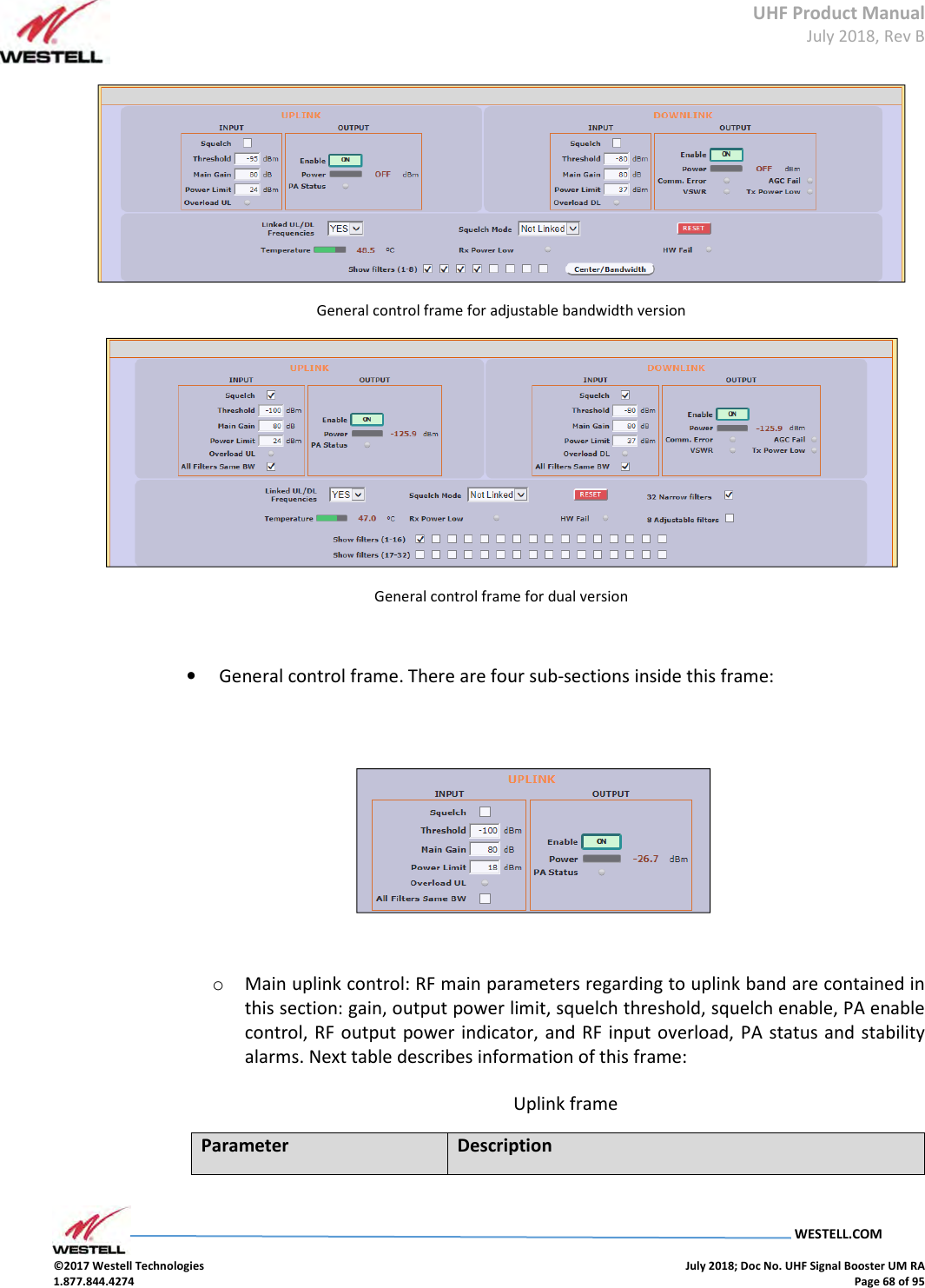
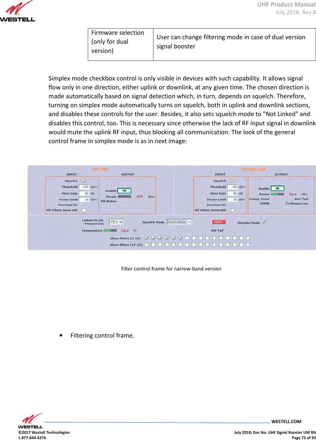
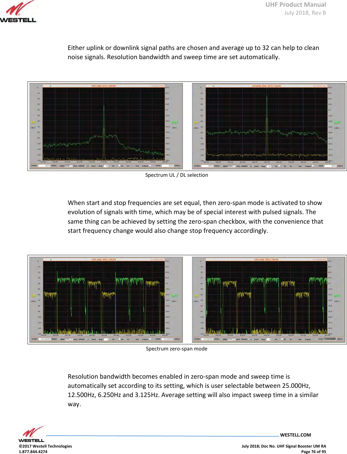
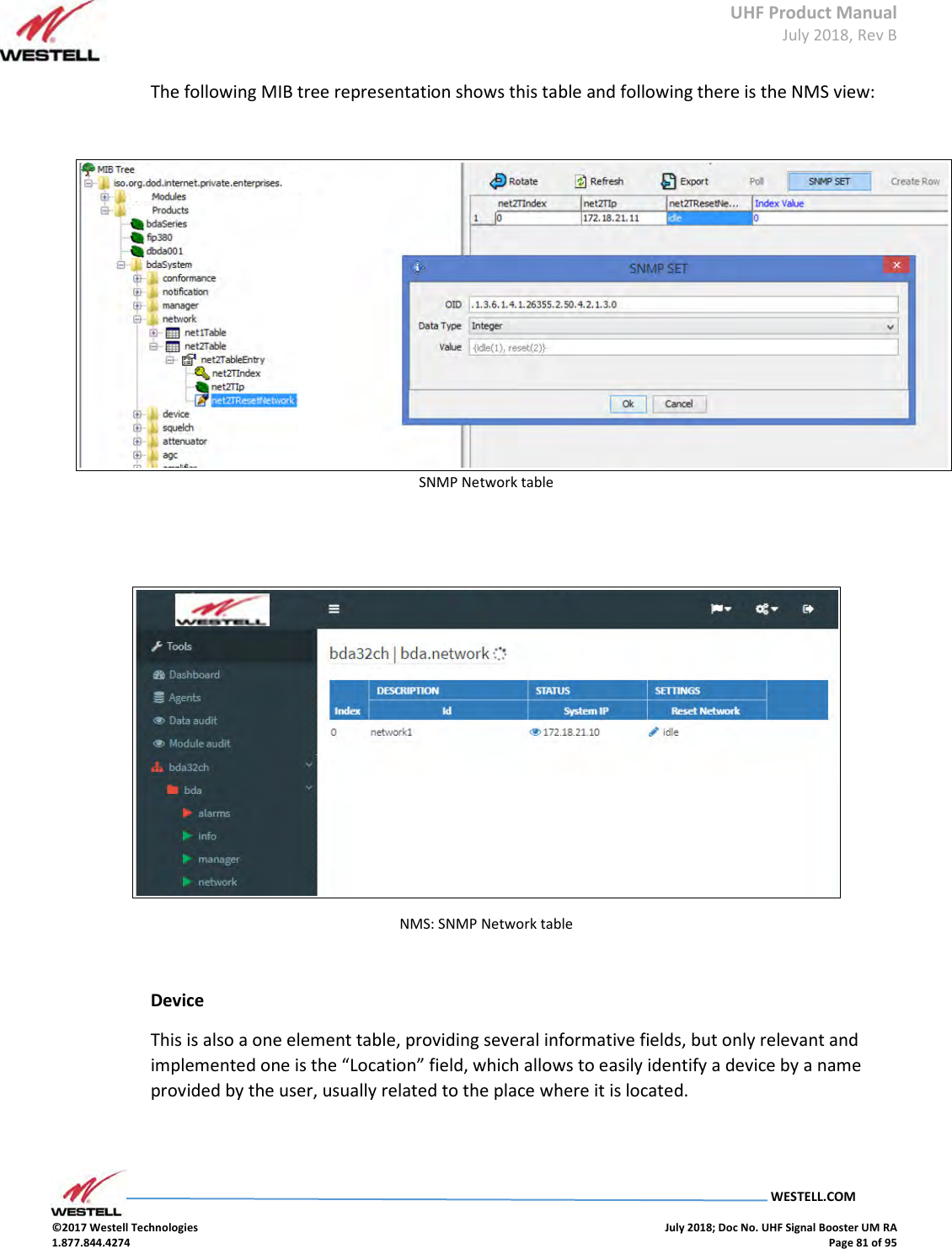
![UHF Product Manual July 2018, Rev B WESTELL.COM ©2017 Westell Technologies July 2018; Doc No. UHF Signal Booster UM RA 1.877.844.4274 Page 80 of 95 The following picture shows the same table as seen by the Westell NMS: NMS: SNMP Managers table Network This is a table has just one element with two items. The first one is the device's IP address and it is read-only to avoid unwanted miss-configuration. This can only be changed by means of the embedded web server or locally, through USB, by means of the Westell Control Software. The second item is a “kind” of button intended for resetting the embedded Ethernet hardware interface. SNMP Network table Field Name OID Description Type Net2TIp[0] 1.3.6.1.4.1.26355.2.50.4.2.1.2.0 IP address R/O Net2TResetNetwork[0] 1.3.6.1.4.1.26355.2.50.4.2.1.3.0 Network reset: reads as idle(1), sets to reset(2) R/W](https://usermanual.wiki/Westell/PSA91080-UHF.User-Manual-Part-2/User-Guide-4027077-Page-30.png)
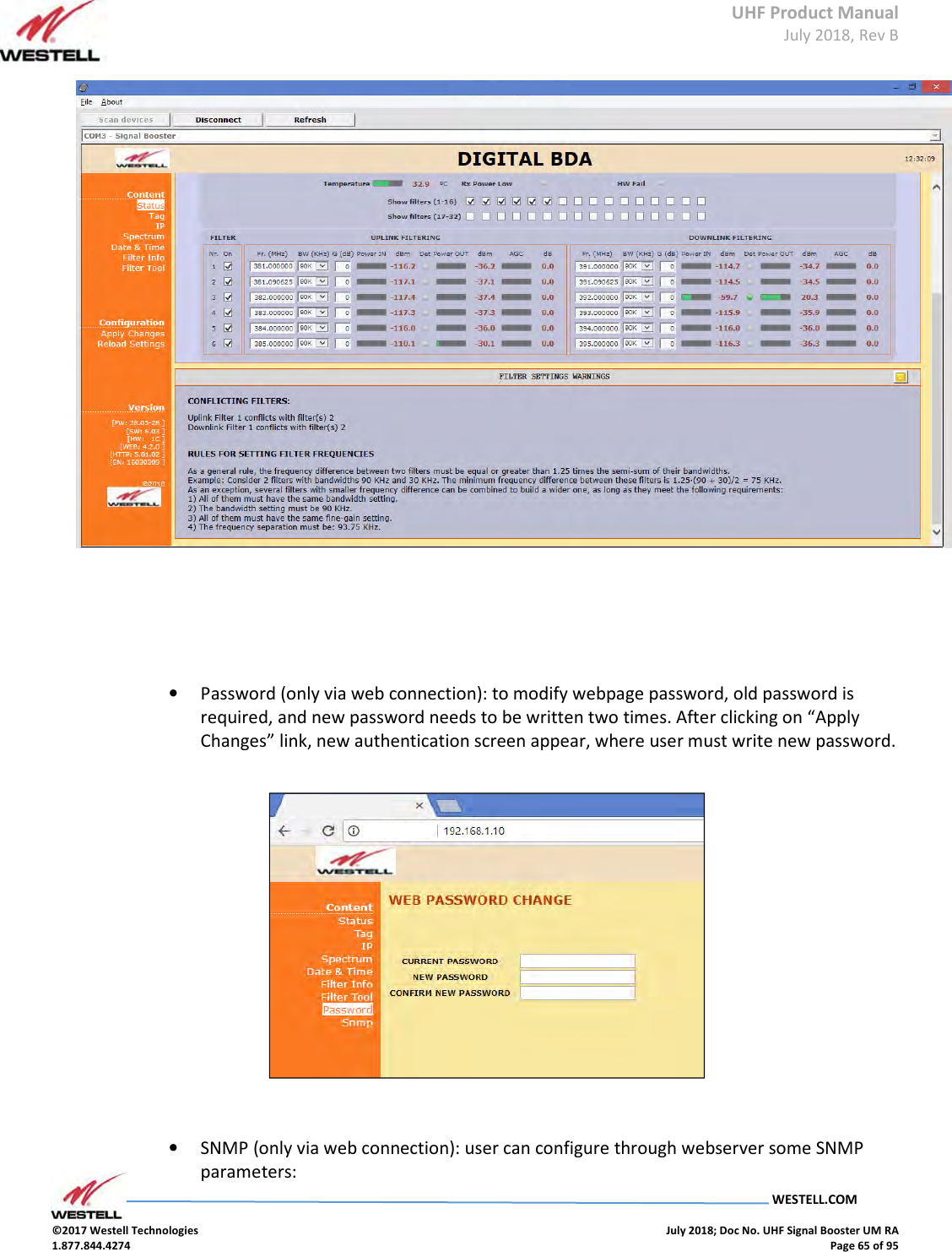
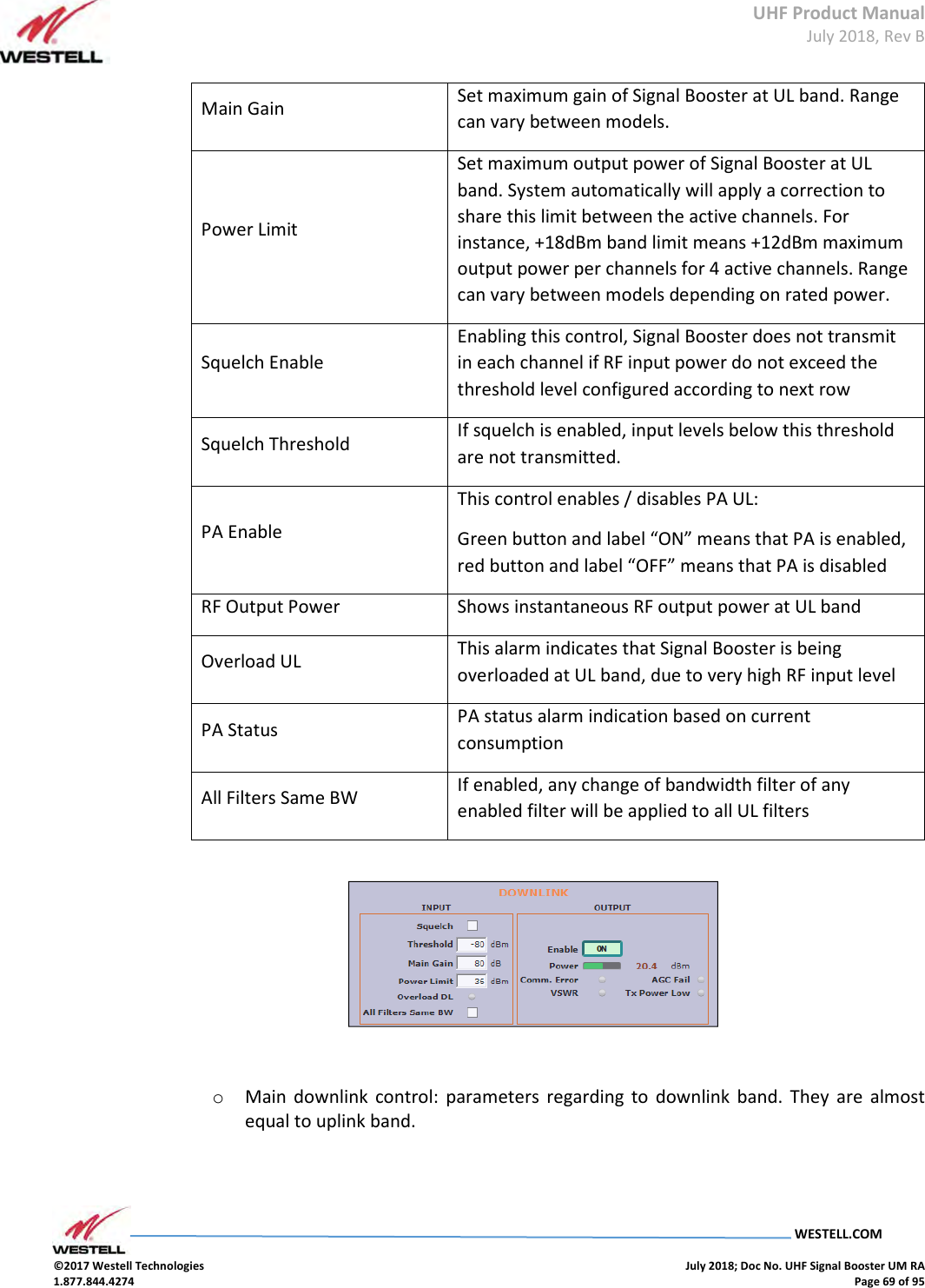
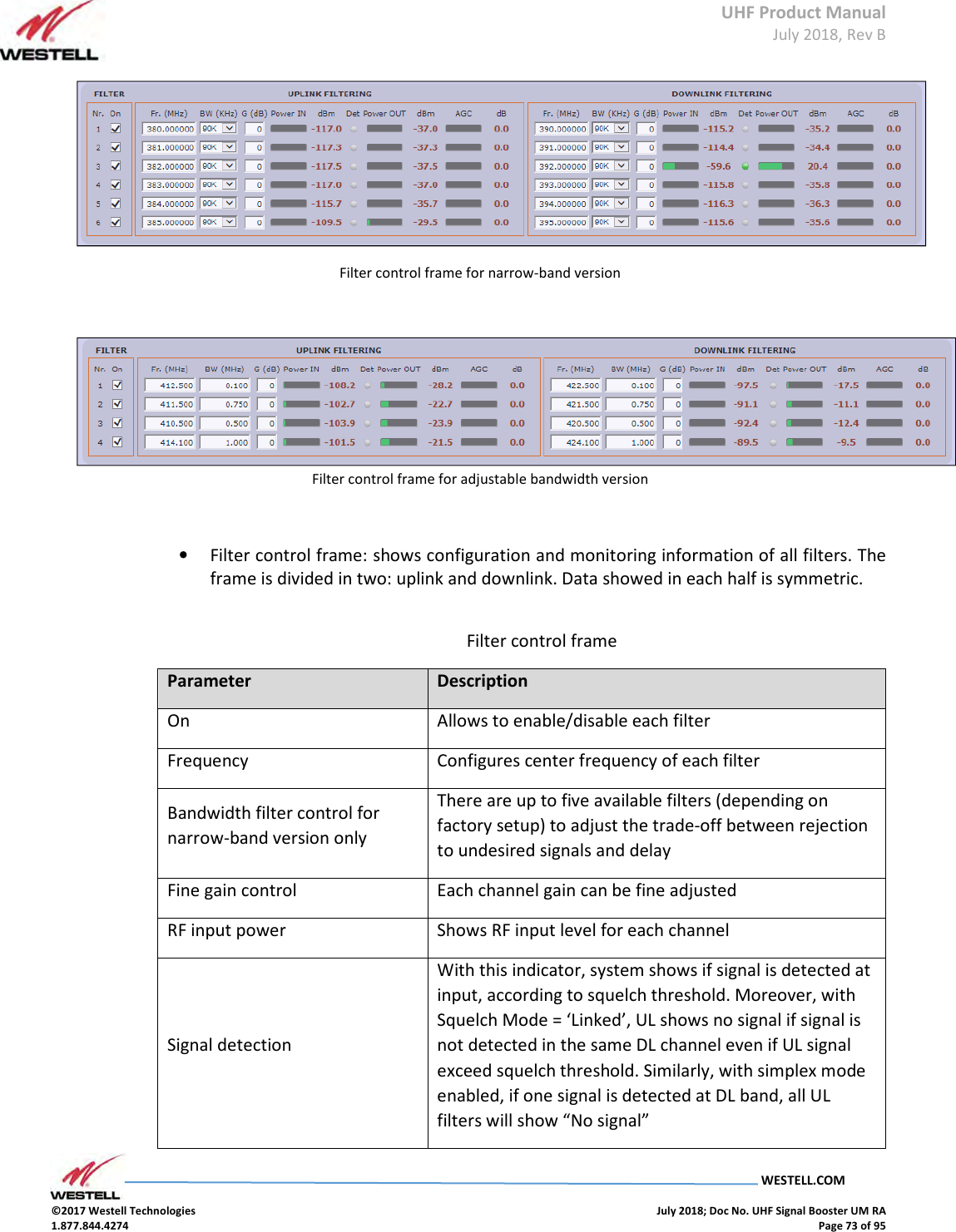
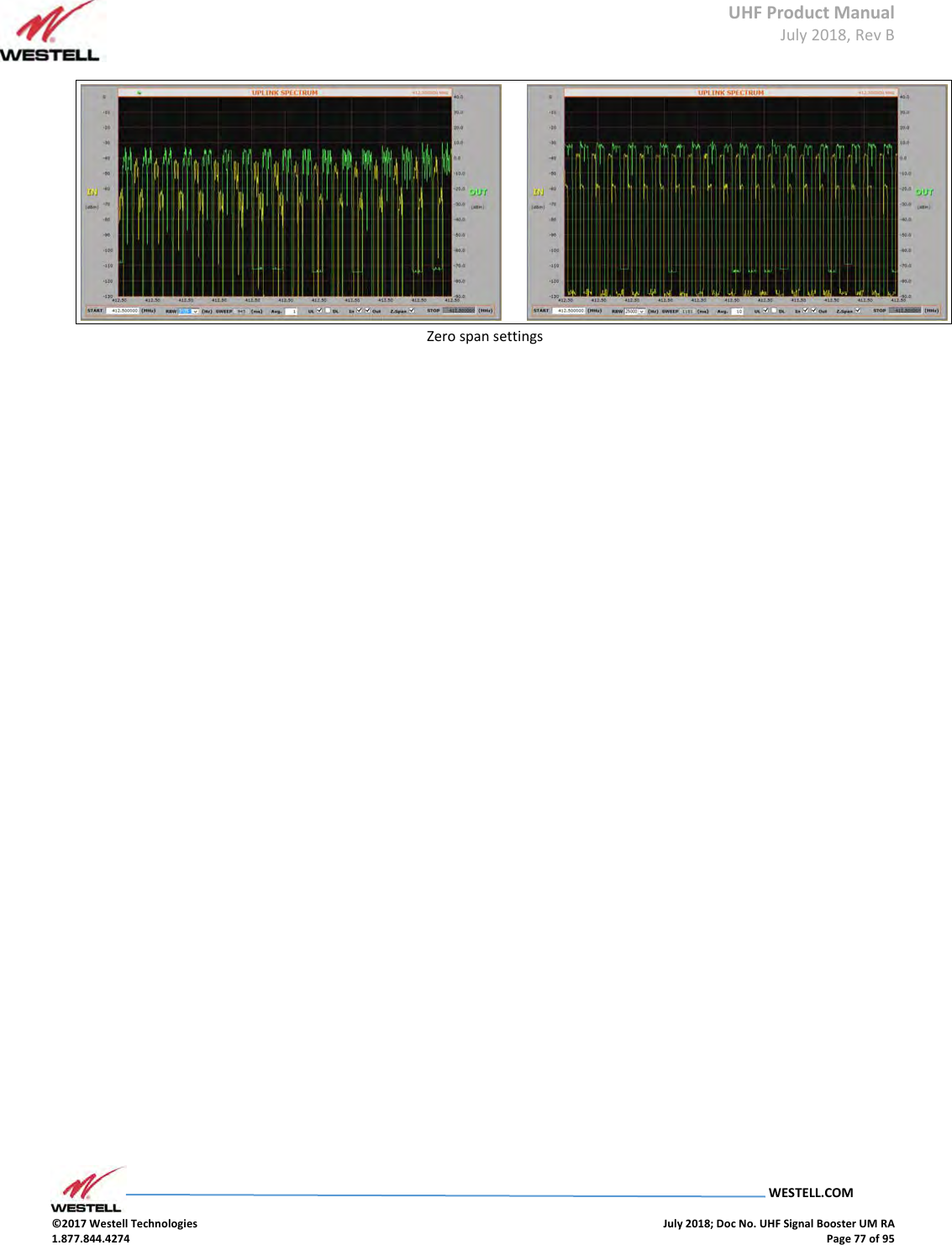
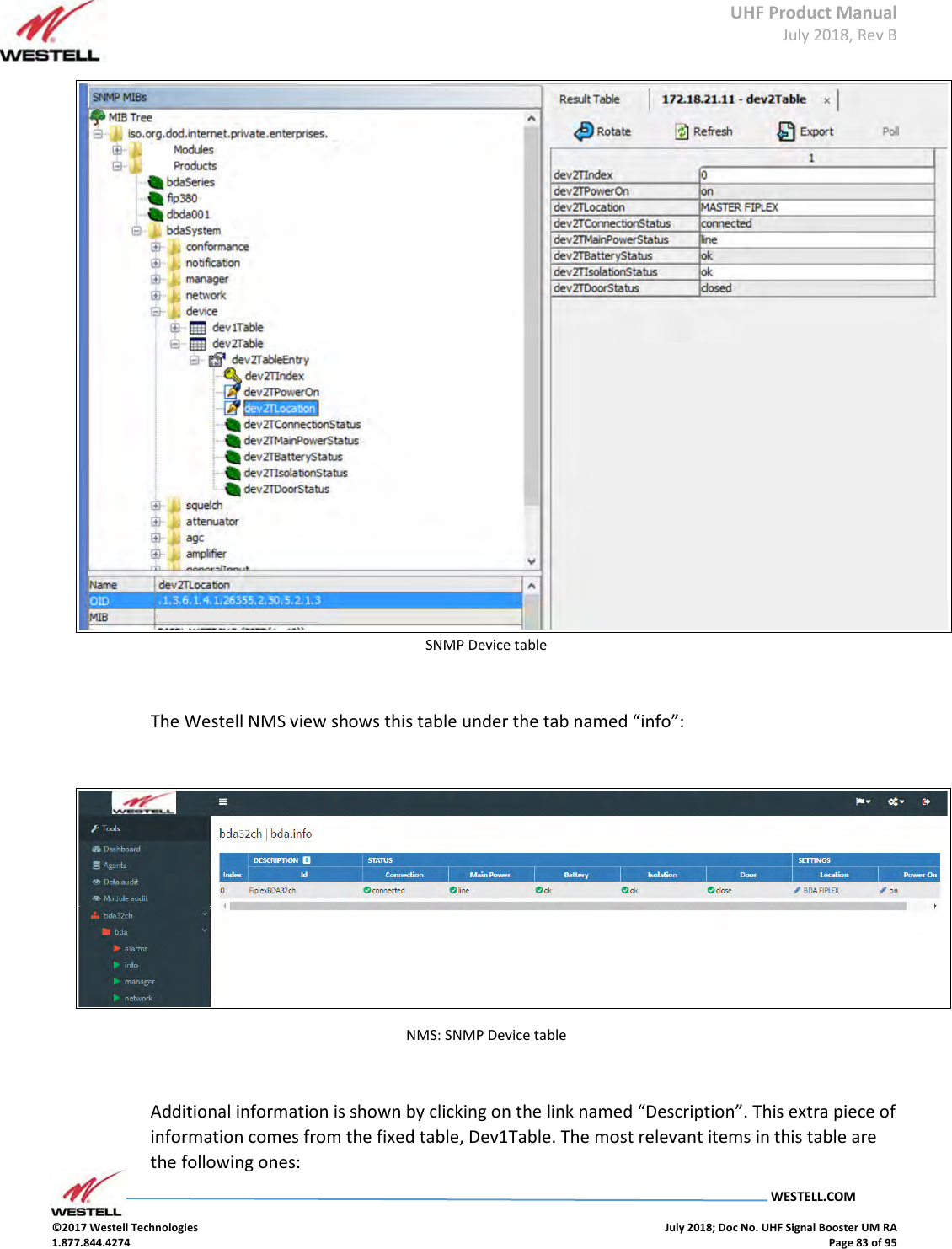
![UHF Product Manual July 2018, Rev B WESTELL.COM ©2017 Westell Technologies July 2018; Doc No. UHF Signal Booster UM RA 1.877.844.4274 Page 82 of 95 SNMP Device table Field Name OID Description Type Dev2TPowerOn[0] 1.3.6.1.4.1.26355.2.50.5.2.1.2.0 - R/W Dev2TLocation[0] 1.3.6.1.4.1.26355.2.50.5.2.1.3.0 String with up to 30 characters R/W Dev2TConnectionStatus[0] 1.3.6.1.4.1.26355.2.50.5.2.1.4.0 - R/O Dev2TMainPowerStatus[0] 1.3.6.1.4.1.26355.2.50.5.2.1.5.0 - R/O Dev2TBatteryStatus[0] 1.3.6.1.4.1.26355.2.50.5.2.1.6.0 - R/O Dev2TIsolationStatus[0] 1.3.6.1.4.1.26355.2.50.5.2.1.7.0 - R/O Dev2TDoorStatus[0] 1.3.6.1.4.1.26355.2.50.5.2.1.8.0 - R/O MIB tree view:](https://usermanual.wiki/Westell/PSA91080-UHF.User-Manual-Part-2/User-Guide-4027077-Page-32.png)
![UHF Product Manual July 2018, Rev B WESTELL.COM ©2017 Westell Technologies July 2018; Doc No. UHF Signal Booster UM RA 1.877.844.4274 Page 84 of 95 SNMP Device Group table Field Name OID Description Type Dev1TGroup[0] 1.3.6.1.4.1.26355.2.50.5.1.1.3.0 das.info (conformance group) R/O Dev1TurlExtern[0] 1.3.6.1.4.1.26355.2.50.5.1.1.19.0 URL of embedded web server R/O Alarms Alarms tables provide information regarding the status of key parts in the system. The fixed table gralAlarm1Table provides self-explanatory identifiers, gralAlarm1TId, for each relevant subject. The second item in each element of this table is the gralAlarm1TGroup. When the device being monitored is a Remote unit, this item just takes the value 'das.alarms '. However, since the Master unit carries information from all the devices in the whole DAS system, it provides a different value for each device to which the alarm is assigned to, be it the Master unit, any of the Remote units or any of the Expansion units. Therefore, the actual number of elements in this table for the Master unit, depends on how many devices compose the DAS system. The third item of each element, gralAlarm1TDescription, is left blank, since the first one suffices for that purpose. SNMP Alarm Group table Field Name OID Description Type GralAlarm1TId[0] 1.3.6.1.4.1.26355.2.50.13.1.1.2.0 Descriptive identifier string R/O GralAlarm1TGroup[0] 1.3.6.1.4.1.26355.2.50.13.1.1.3.0 Conformance group for general alarms R/O GralAlarm1TDescription[0] 1.3.6.1.4.1.26355.2.50.13.1.1.4.0 - R/O](https://usermanual.wiki/Westell/PSA91080-UHF.User-Manual-Part-2/User-Guide-4027077-Page-34.png)
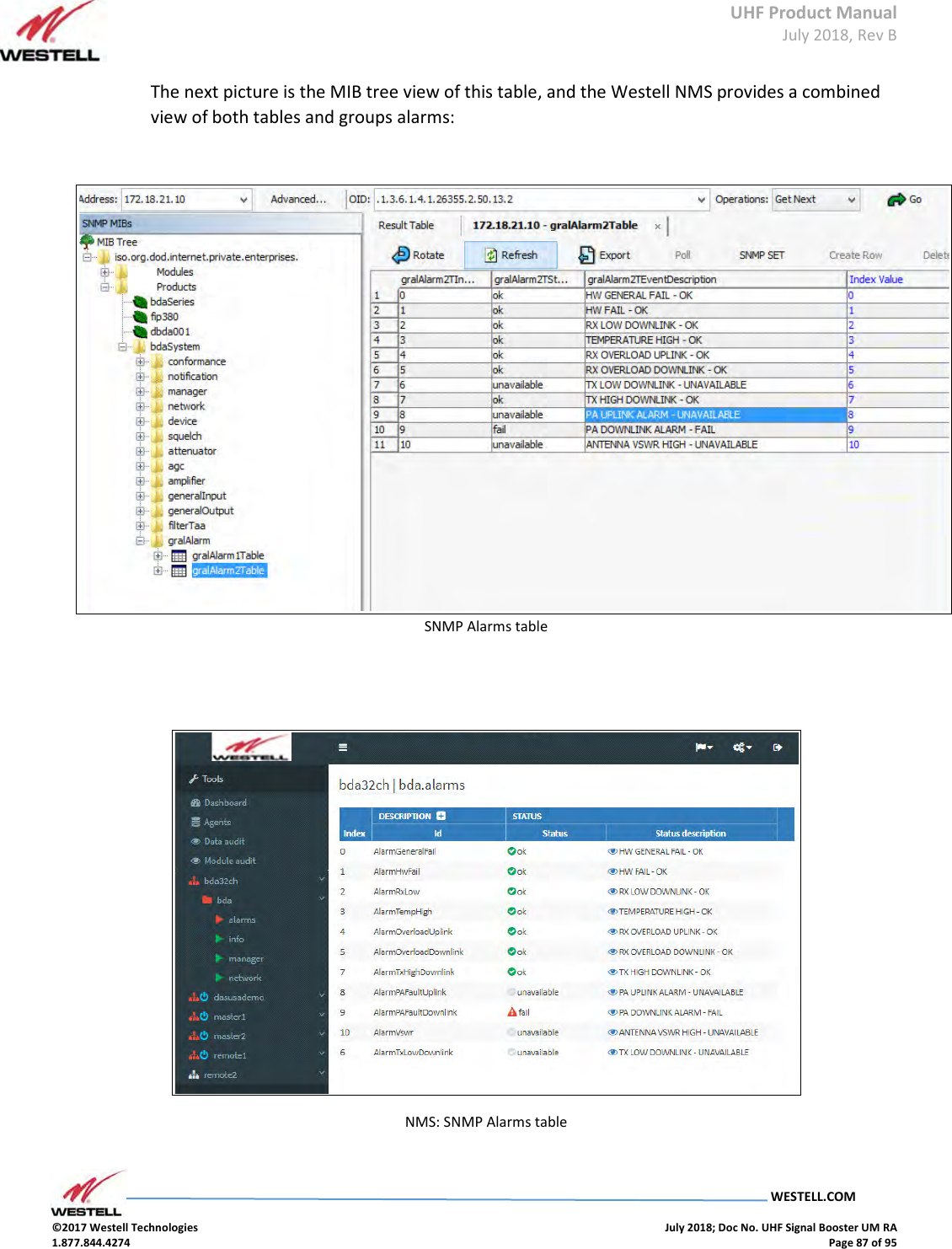
![UHF Product Manual July 2018, Rev B WESTELL.COM ©2017 Westell Technologies July 2018; Doc No. UHF Signal Booster UM RA 1.877.844.4274 Page 86 of 95 SNMP Alarms Group table On the other hand, the mutable table gralAlarm2Table provides the actual status of each alarm. This table has one element for each element in gralAlarm1Table. Each element has two items. The first one is a status identifier, gralAlarm2TStatus, be it 'ok', 'warning', 'fail' or 'unavailable'. The second item is a short description of the fault, mainly for human readability. SNMP Alarm table 2 Field Name OID Description Type GralAlarm2TStatus[0] 1.3.6.1.4.1.26355.2.50.13.2.1.2.0 Status enumeration R/O GralAlarm2TEventDescription[0] 1.3.6.1.4.1.26355.2.50.13.2.1.3.0 Short descriptive string R/O](https://usermanual.wiki/Westell/PSA91080-UHF.User-Manual-Part-2/User-Guide-4027077-Page-36.png)