Westell 327WXX-6 802.11b/g Wireless ADSL 4port Ethernet/USB Router User Manual users manual page71 to 155
Westell Inc 802.11b/g Wireless ADSL 4port Ethernet/USB Router users manual page71 to 155
Westell >
Contents
- 1. users manual page1 to 70
- 2. users manual page71 to 155
users manual page71 to 155
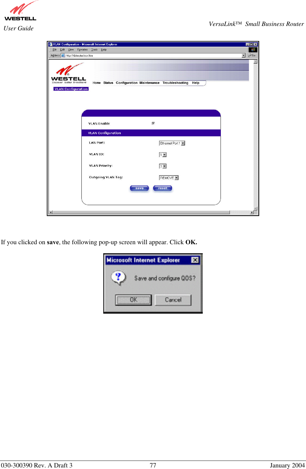
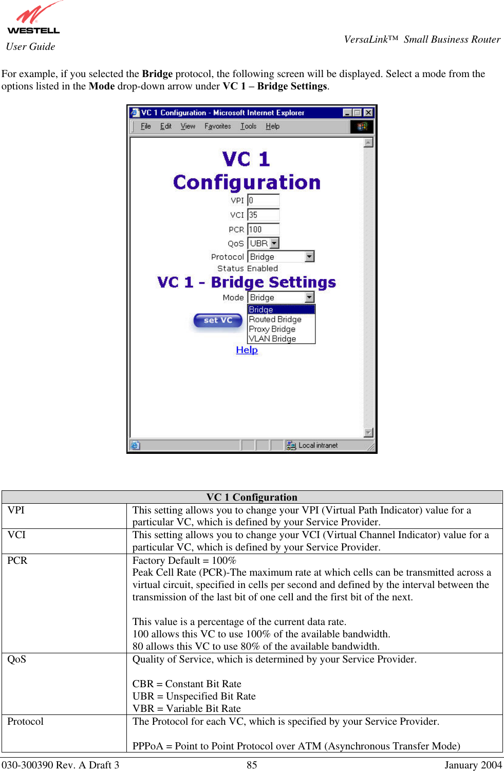
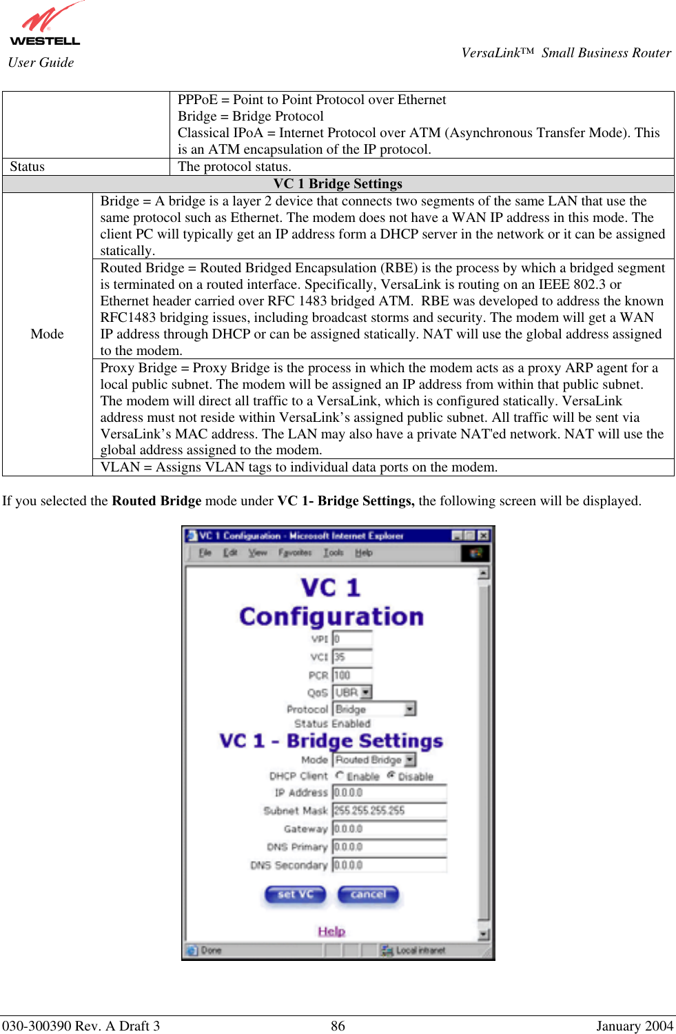
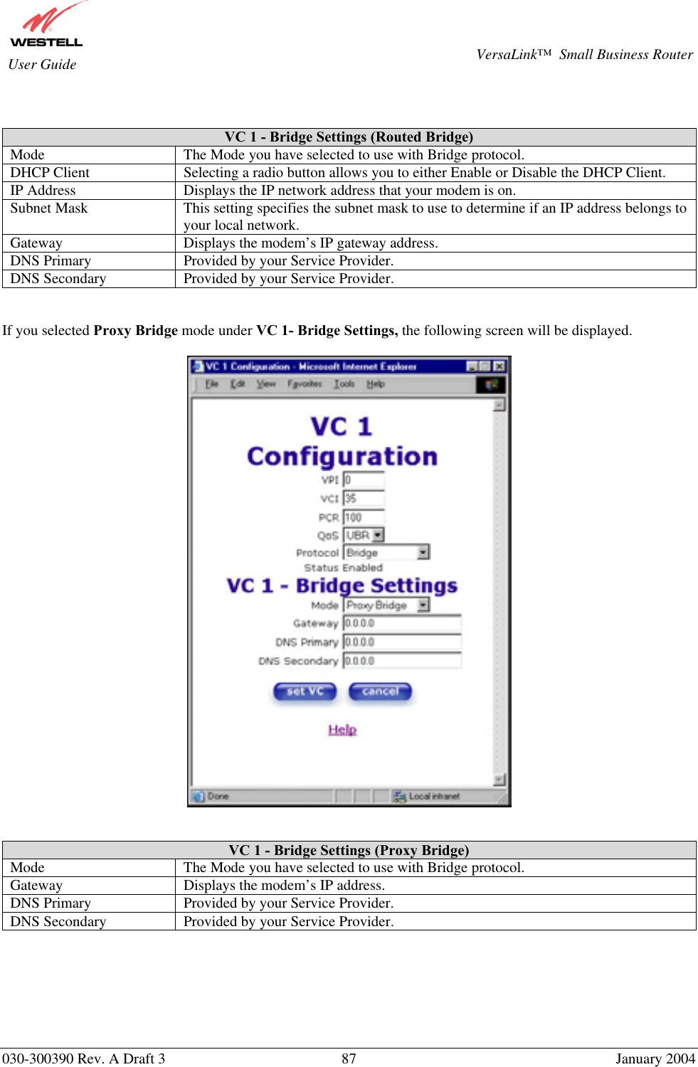
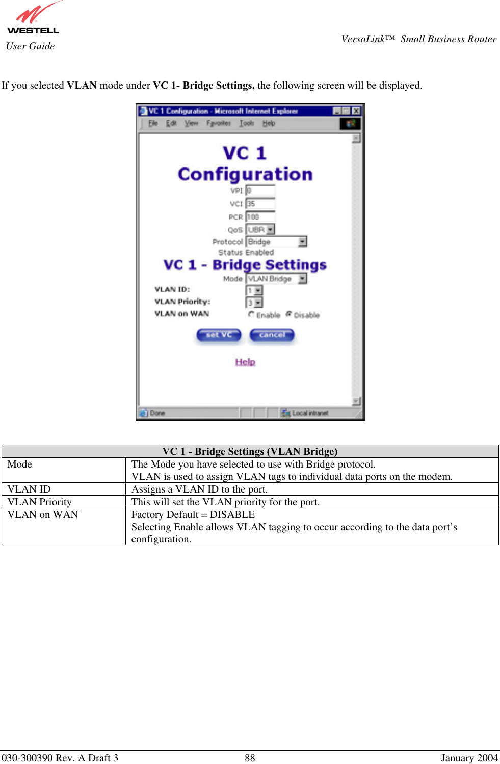
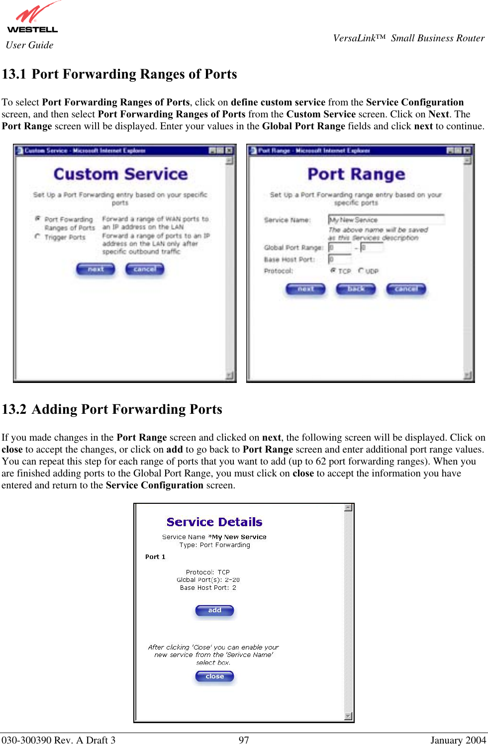
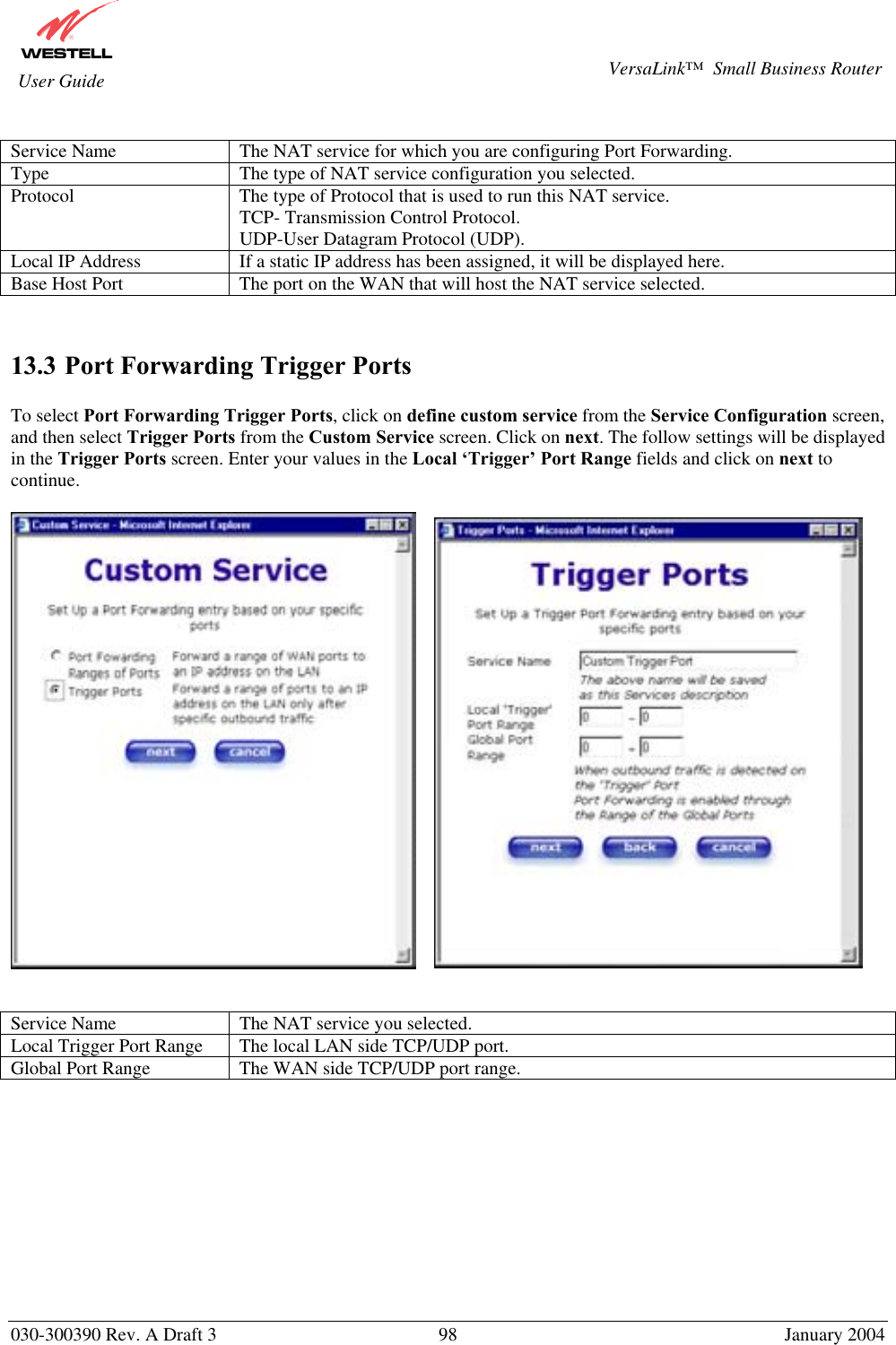
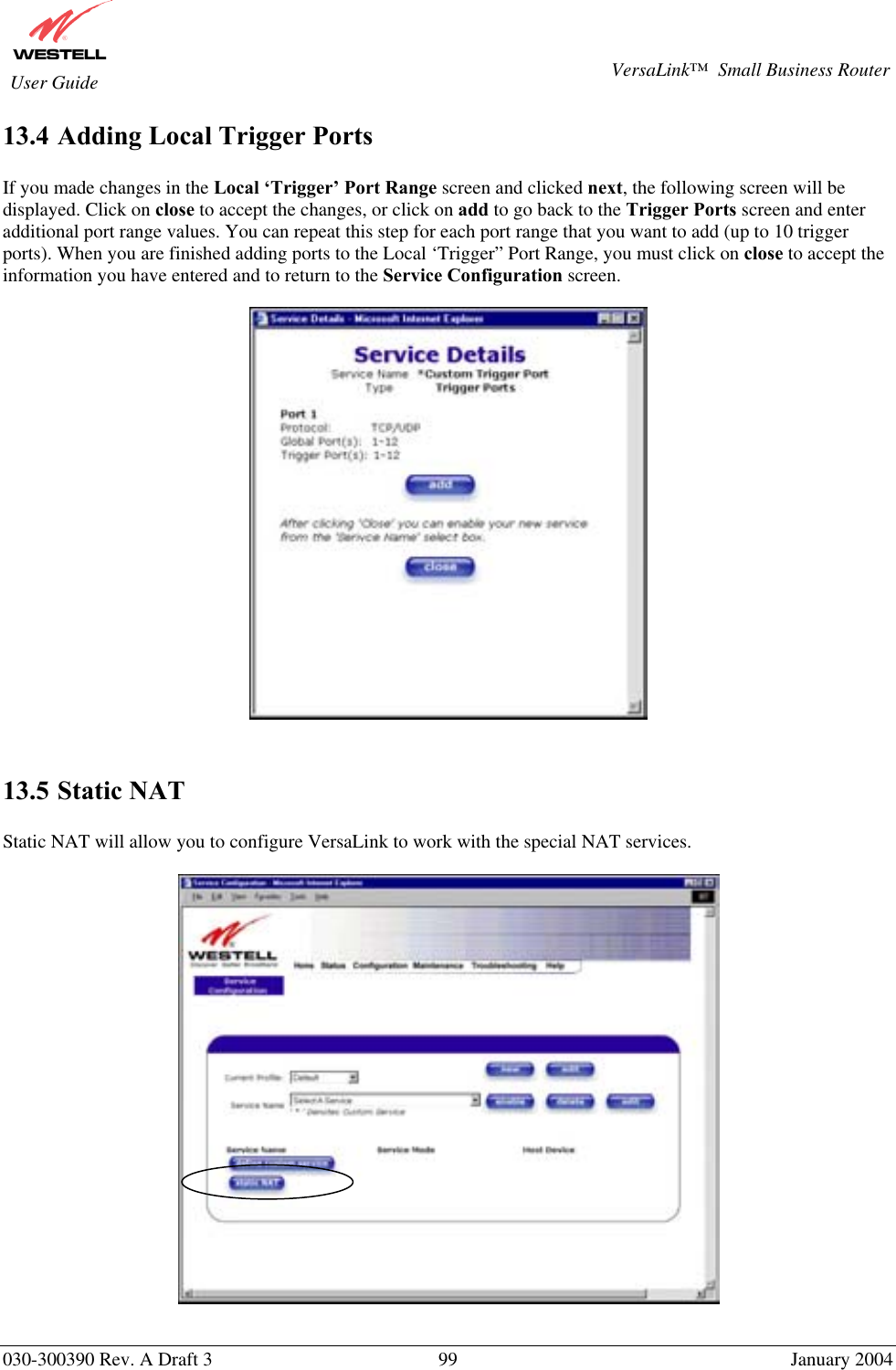
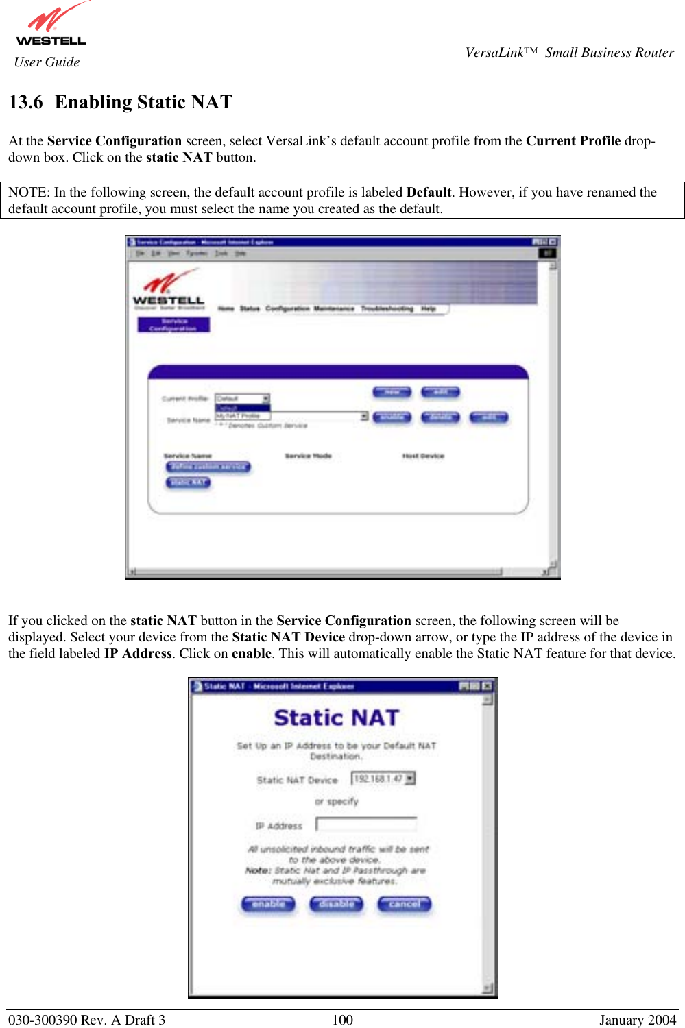
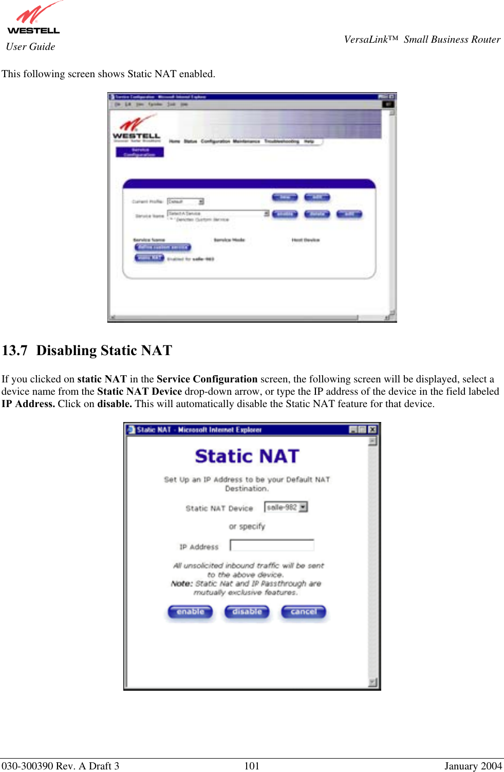
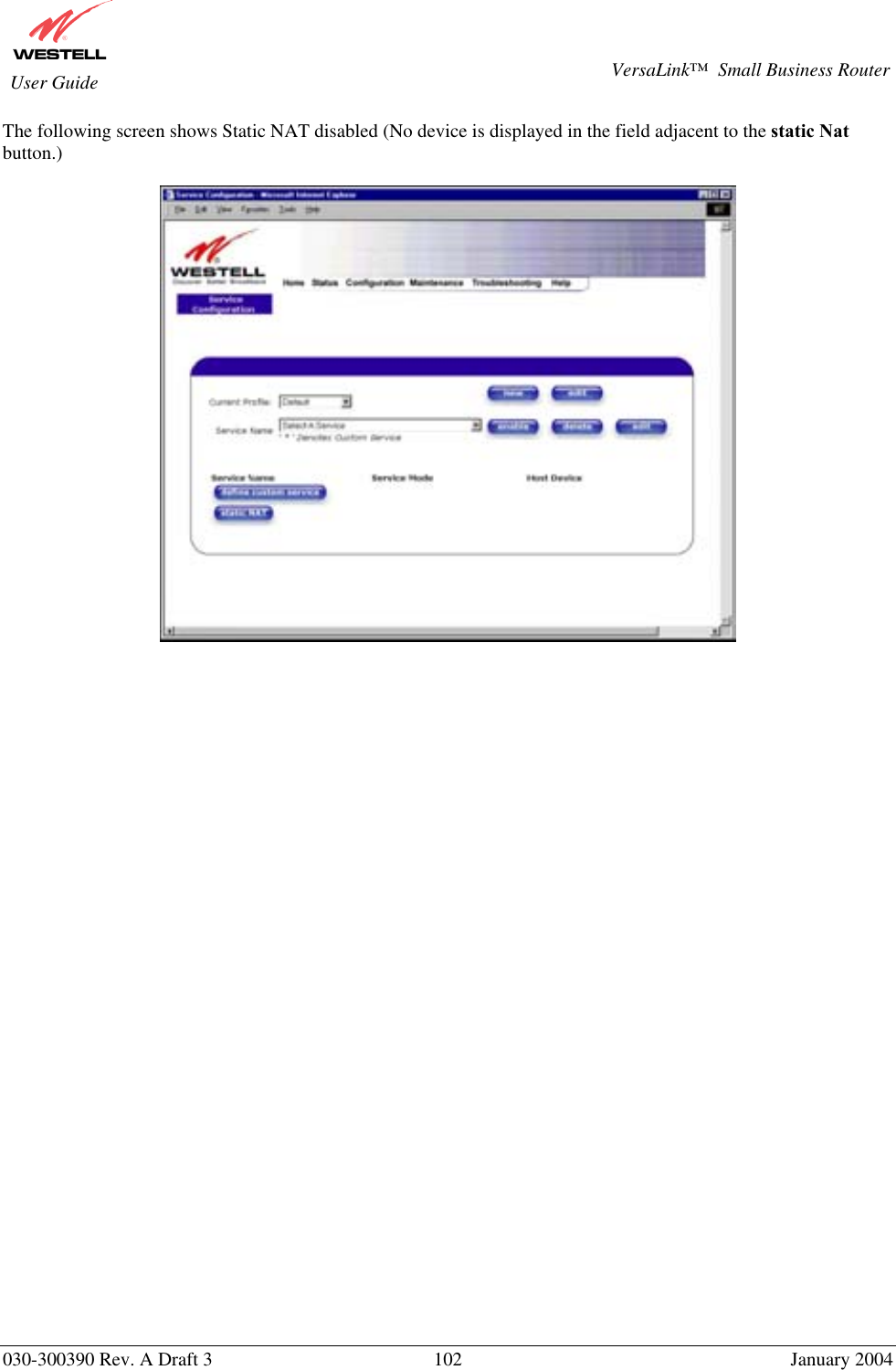
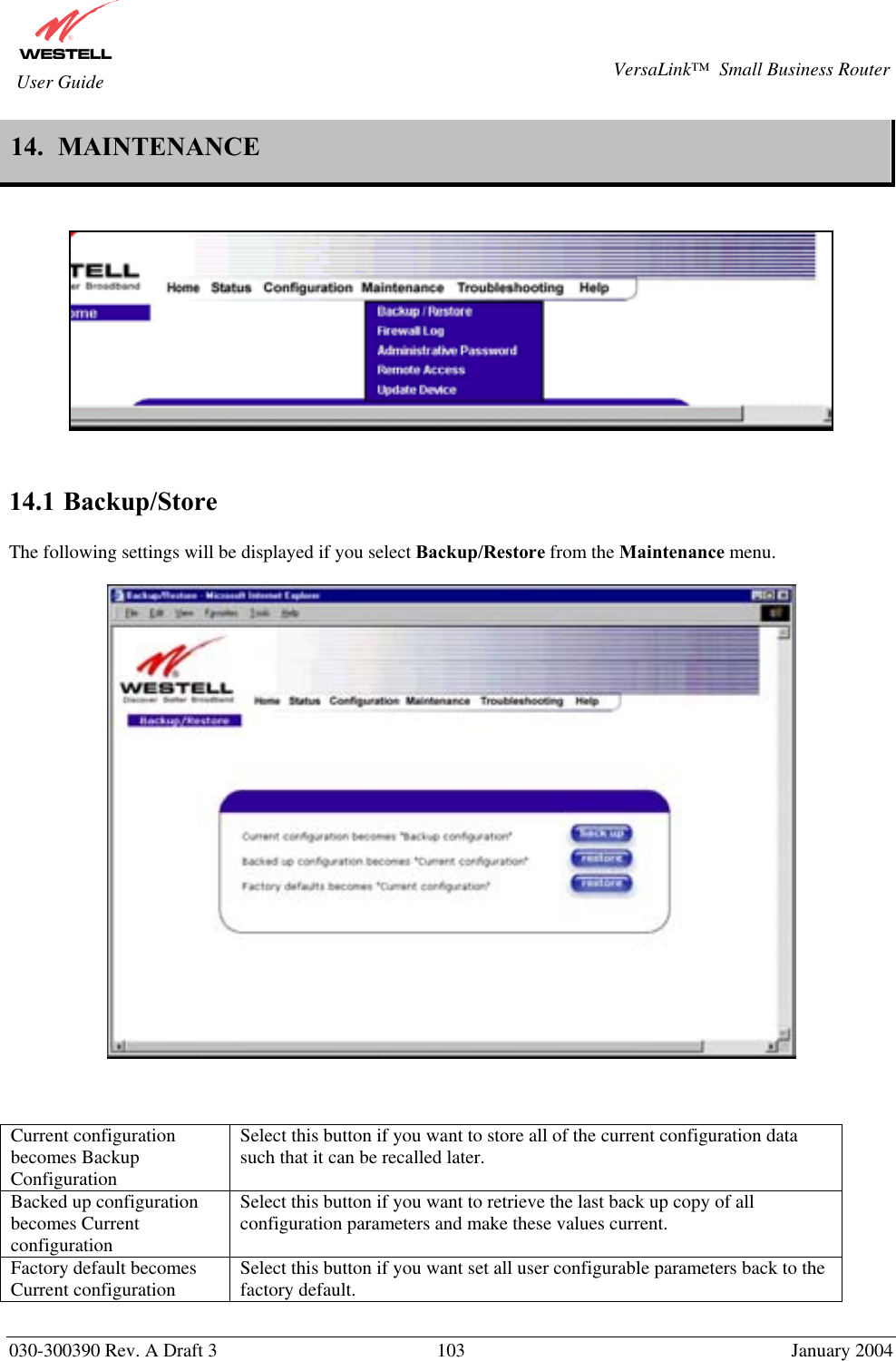
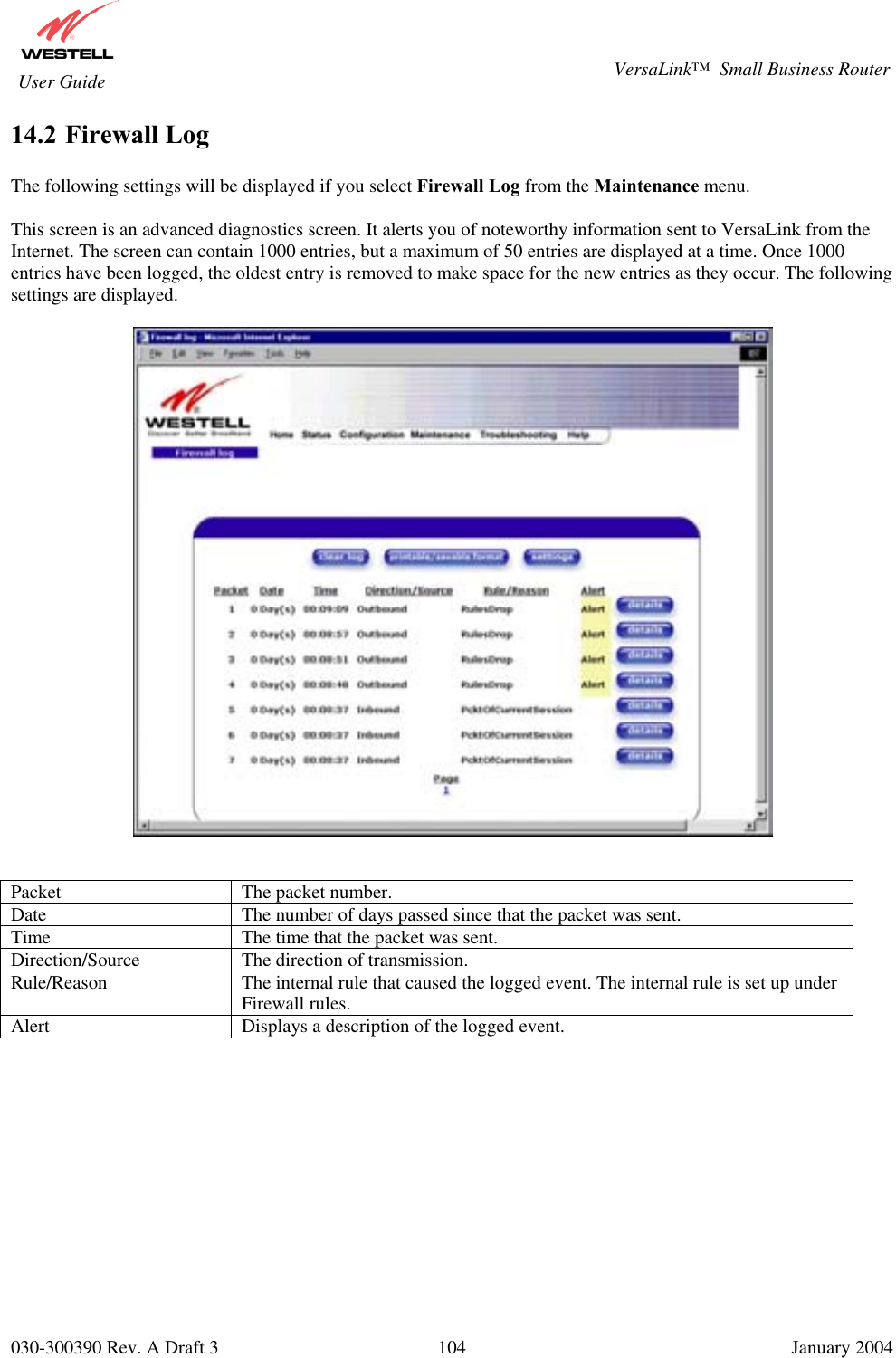
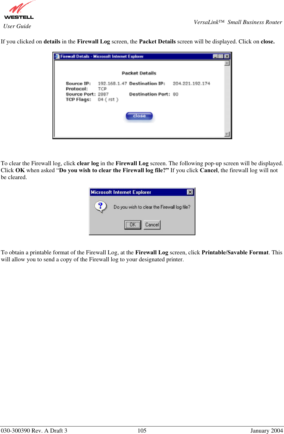
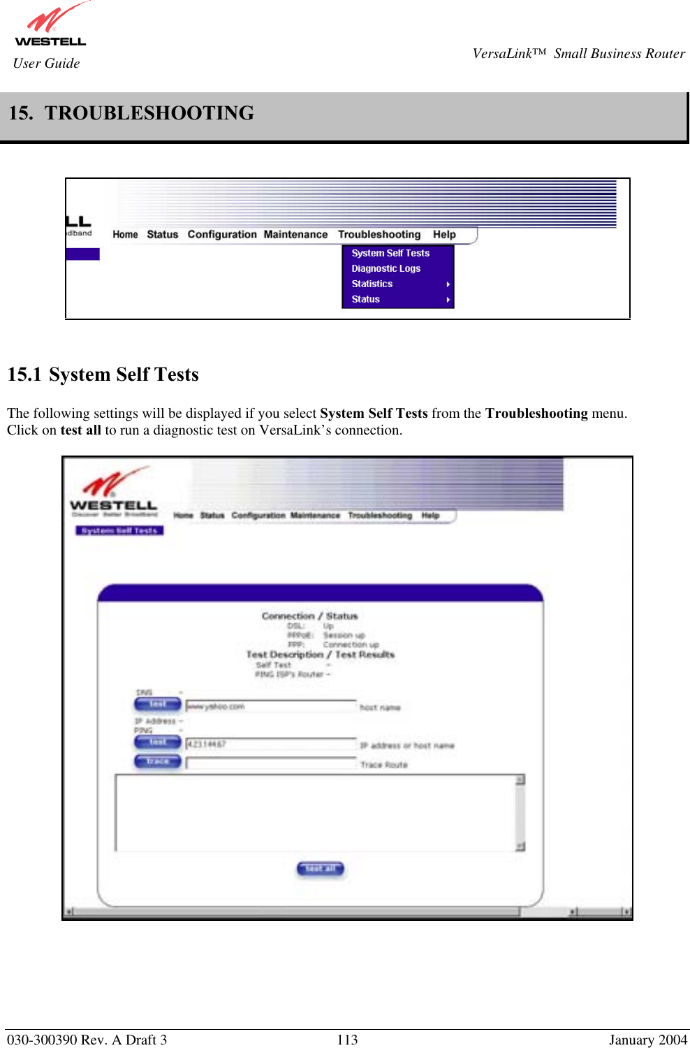
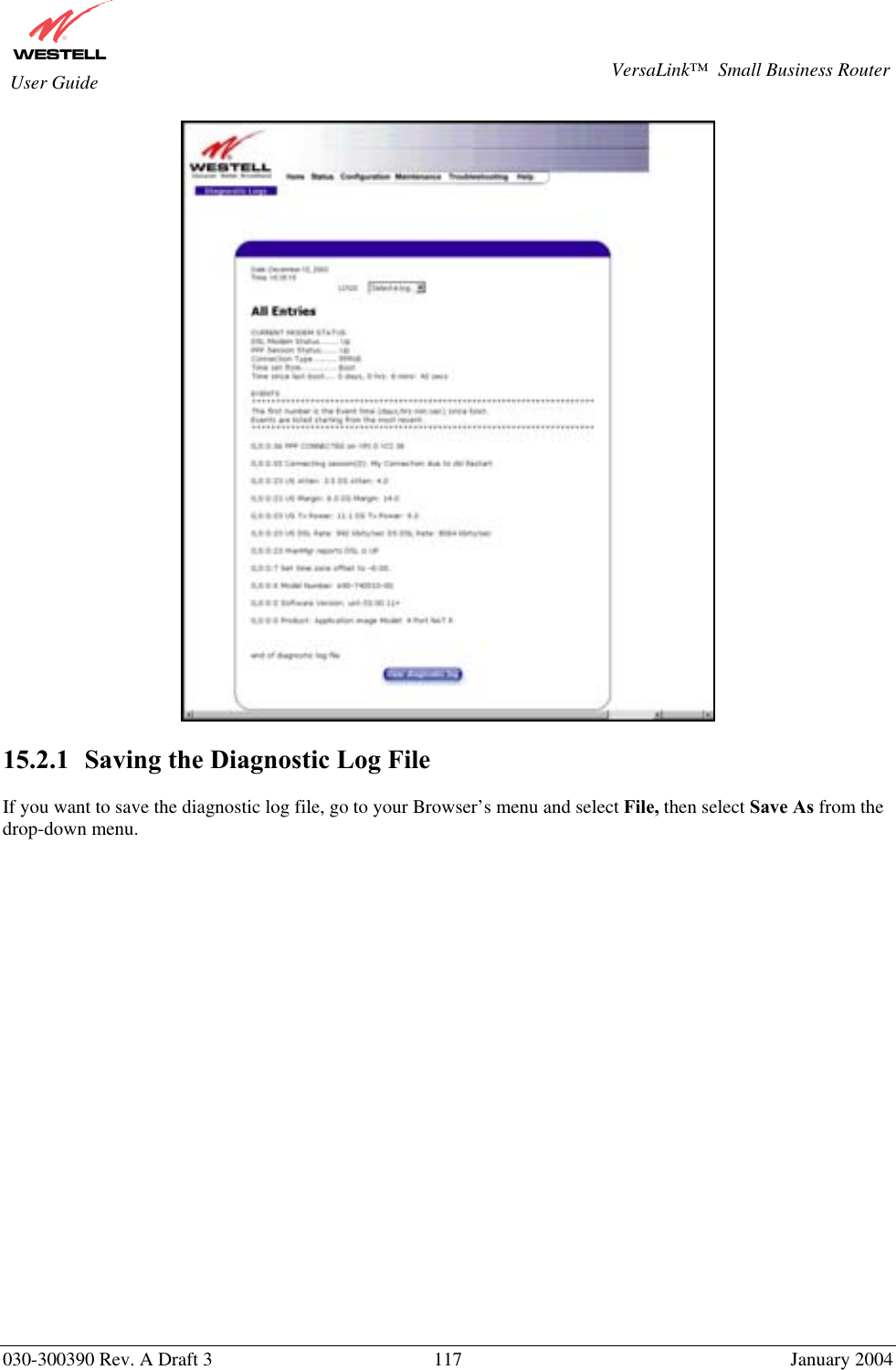
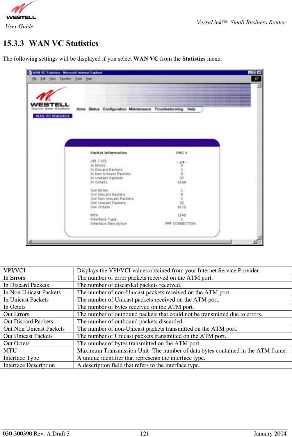
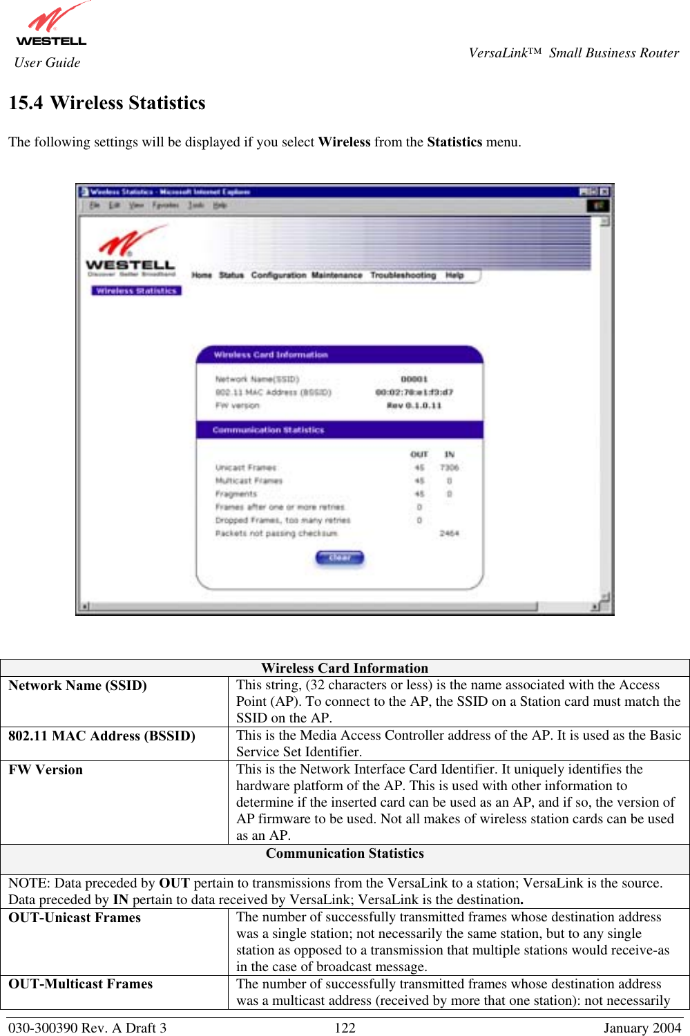
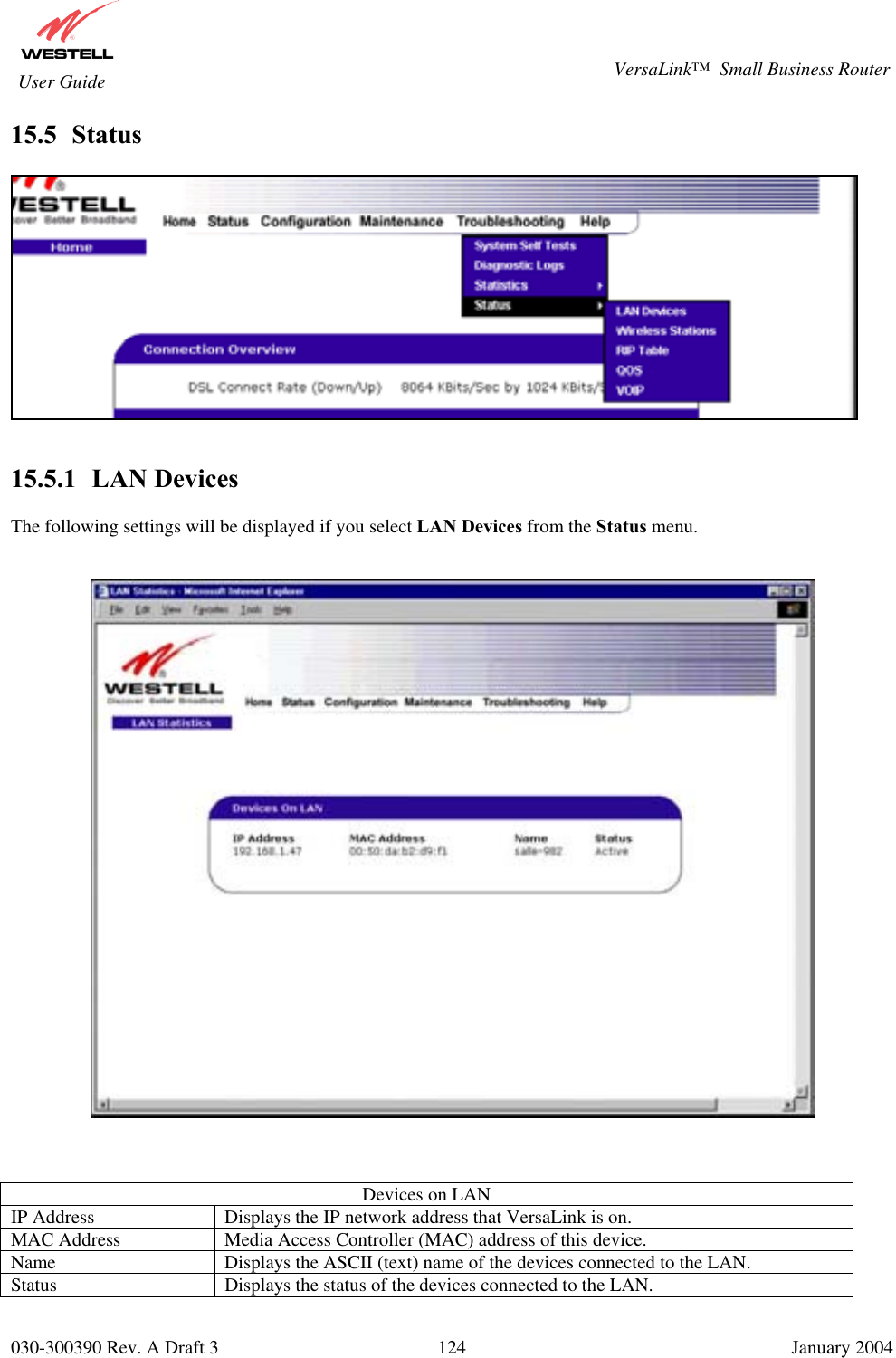
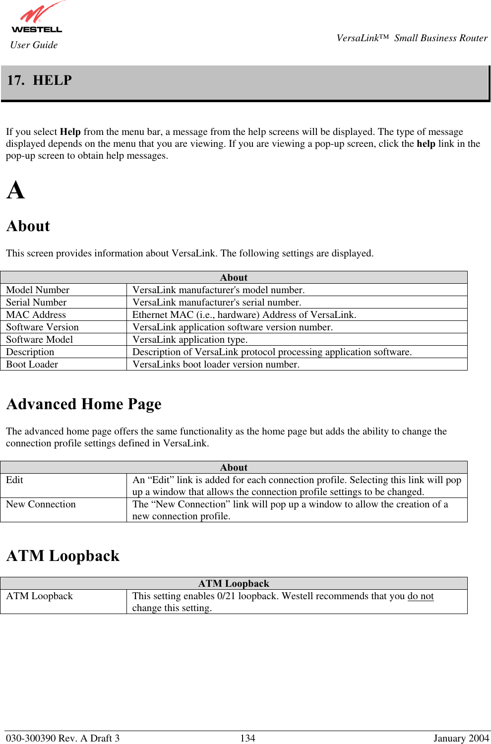
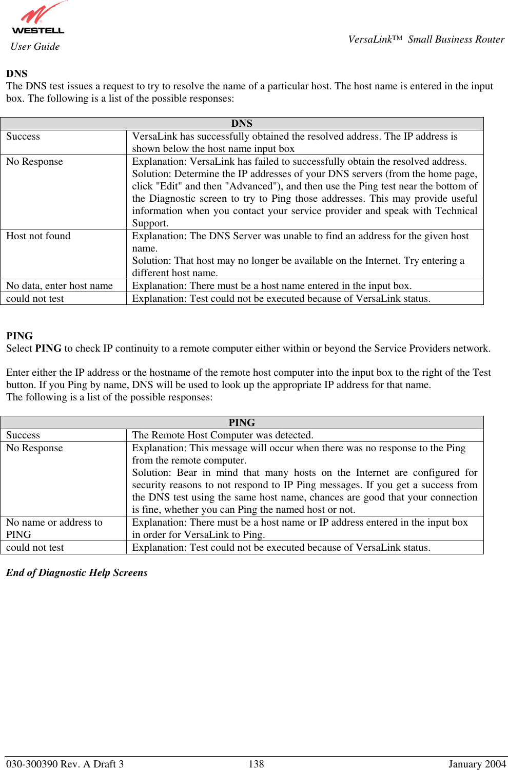
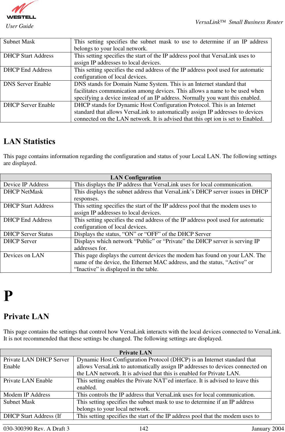
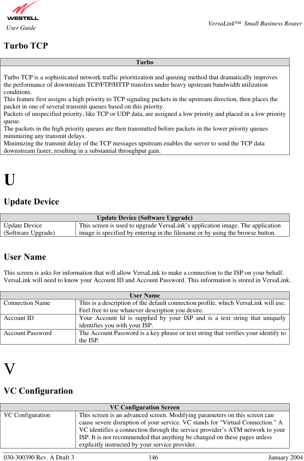
![030-300390 Rev. A Draft 3 133 January 2004 VersaLink™ Small Business Router User Guide Application/Game Port/Protocol Unreal Tournament server 7777 (default gameplay port) 7778 (server query port 7779,7779+ are allocated dynamically for each helper UdpLink objects, including UdpServerUplin objects. Try starting with 7779-7781 and add ports if needed 27900 server query, if master server uplink is enabled. Home master servers use other ports like 27500 Port 8080 is for UT Server Admin. In the [UWeb.WebServer] section of the server.ini file, set the ListenPort to 8080 and ServerName to the IP assigned to VersaLink from your ISP. USENET News Service 143 TCP VNC, Virtual Network Computing 5500 TCP, 5800 TCP, 5900 TCP Westwood Online, C&C 4000 TCP/UDP, 1140-1234 TCP/UDP World Wide Web (HTTP) 80 TCP 443 TCP (SSL) 8008 OR 8080 TCP (PROXY) XBOX Live TCP/UDP 88 and 3074 Yahoo Messenger Chat 5000-5001 TCP Yahoo Messenger Phone 5055 UDP VPN Protocol Comments IPSec Encryption IPSec using AH can not be supported through NAT. IPSec using ESP and L2TP can be supported via an ALG L2TP IPSec using ESP and L2TP can be supported via an ALG. PPTP Works through NAT.](https://usermanual.wiki/Westell/327WXX-6.users-manual-page71-to-155/User-Guide-401962-Page-63.png)