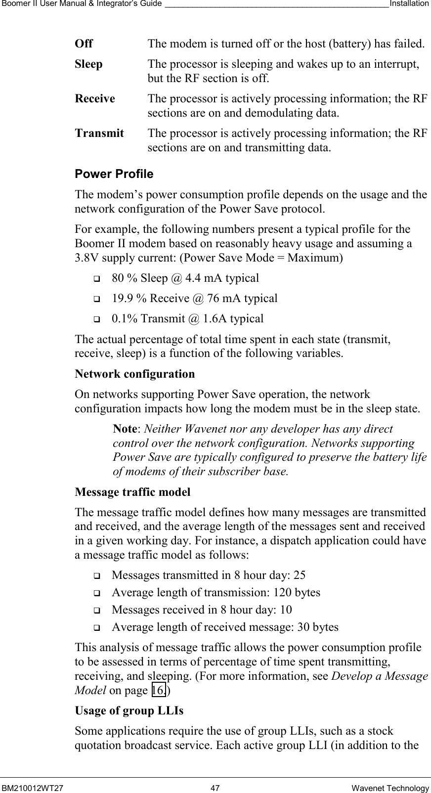
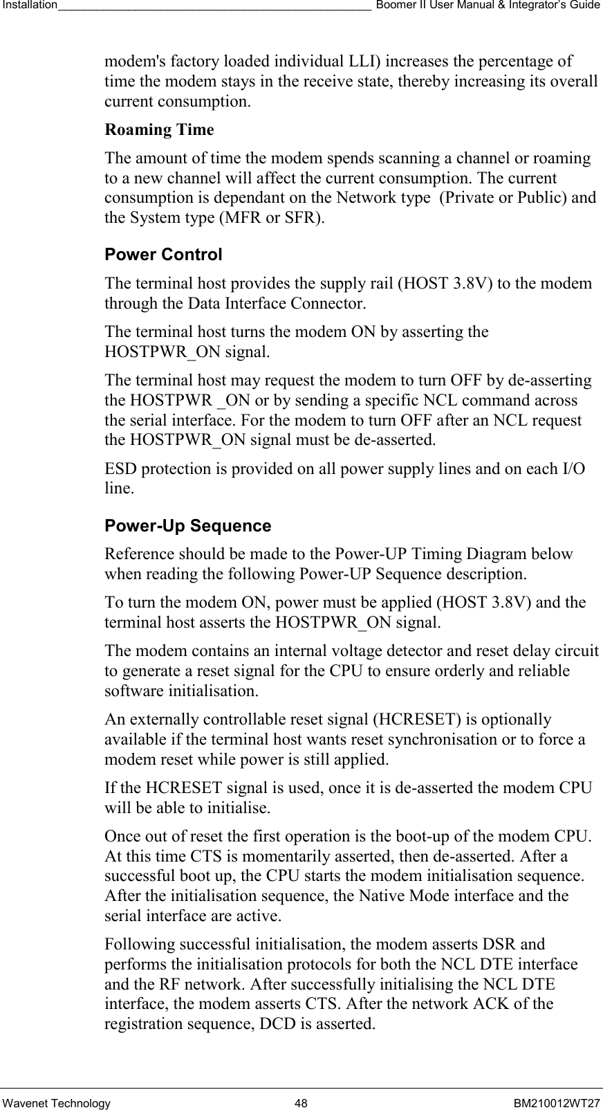
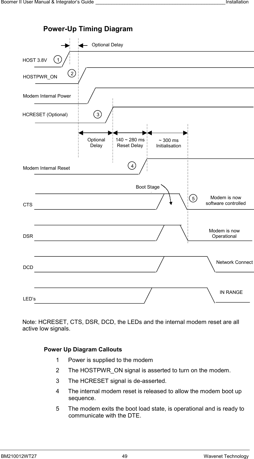
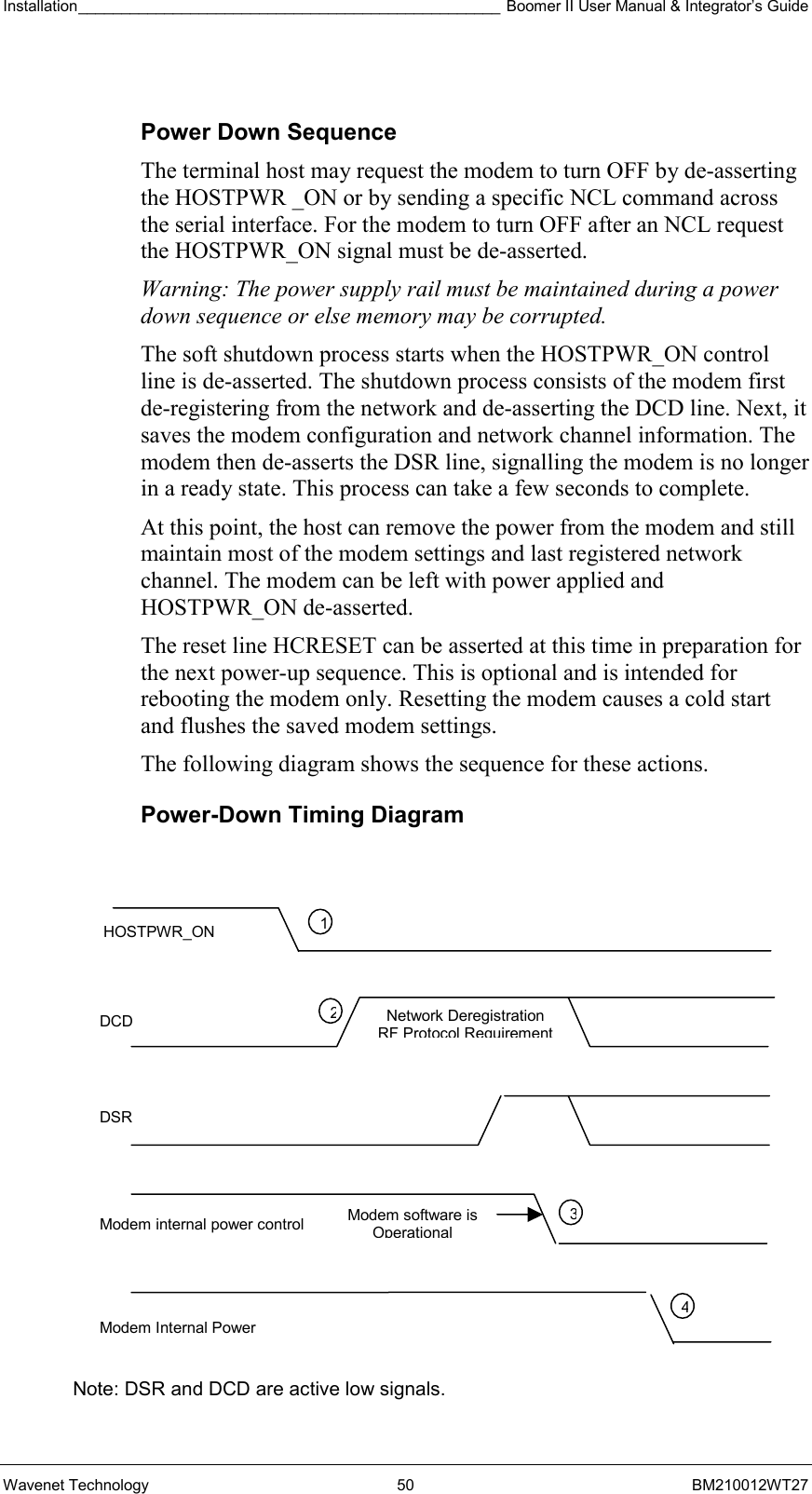
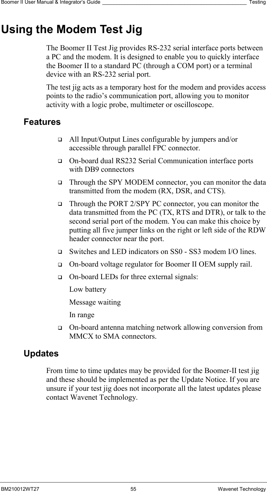
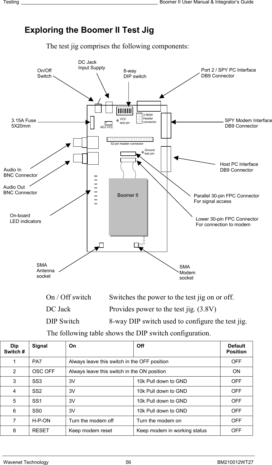
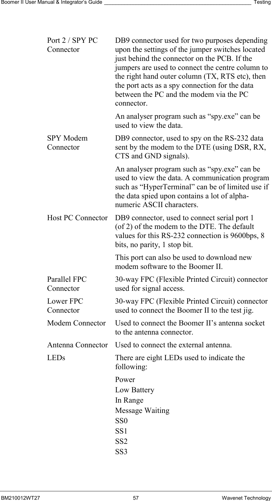
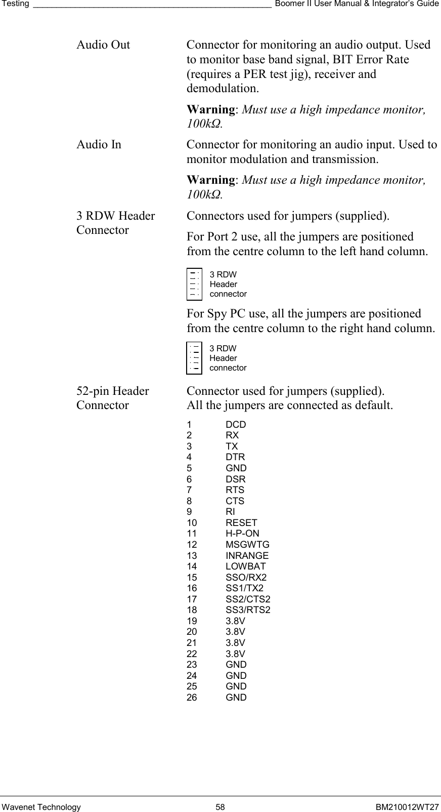
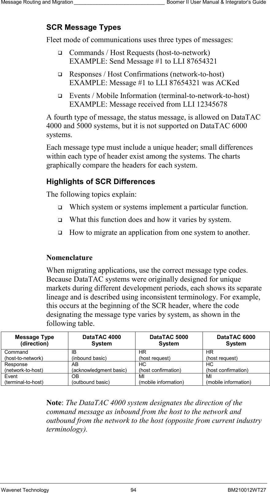
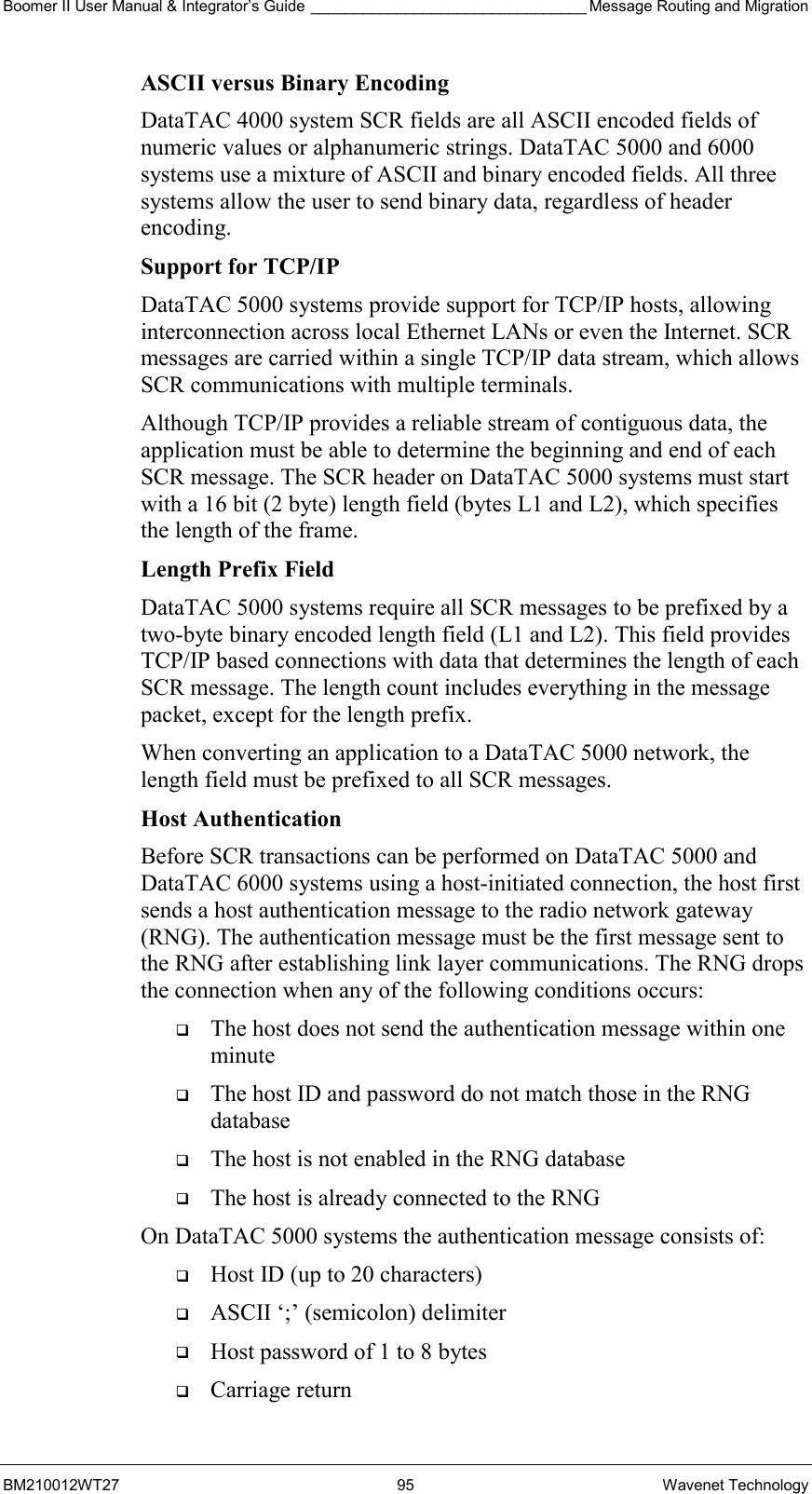
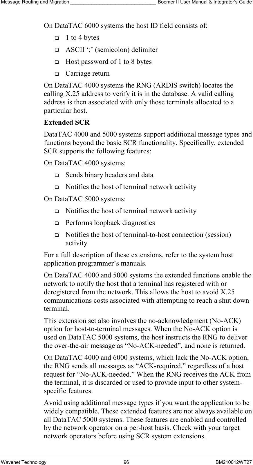
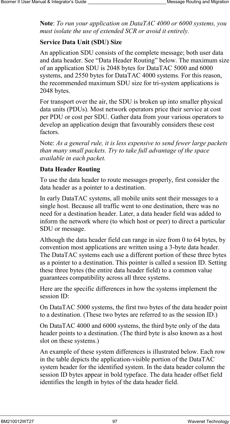
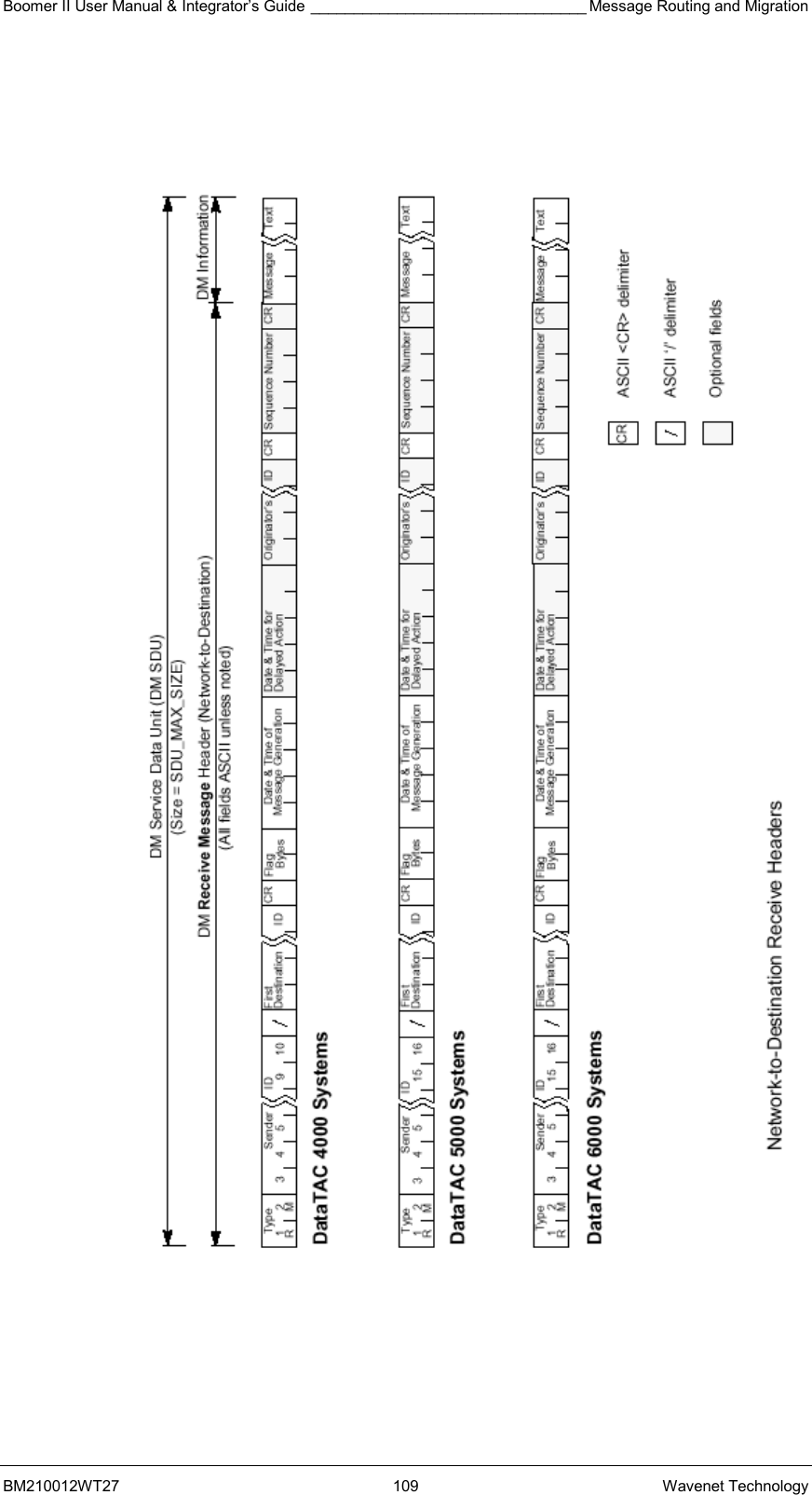
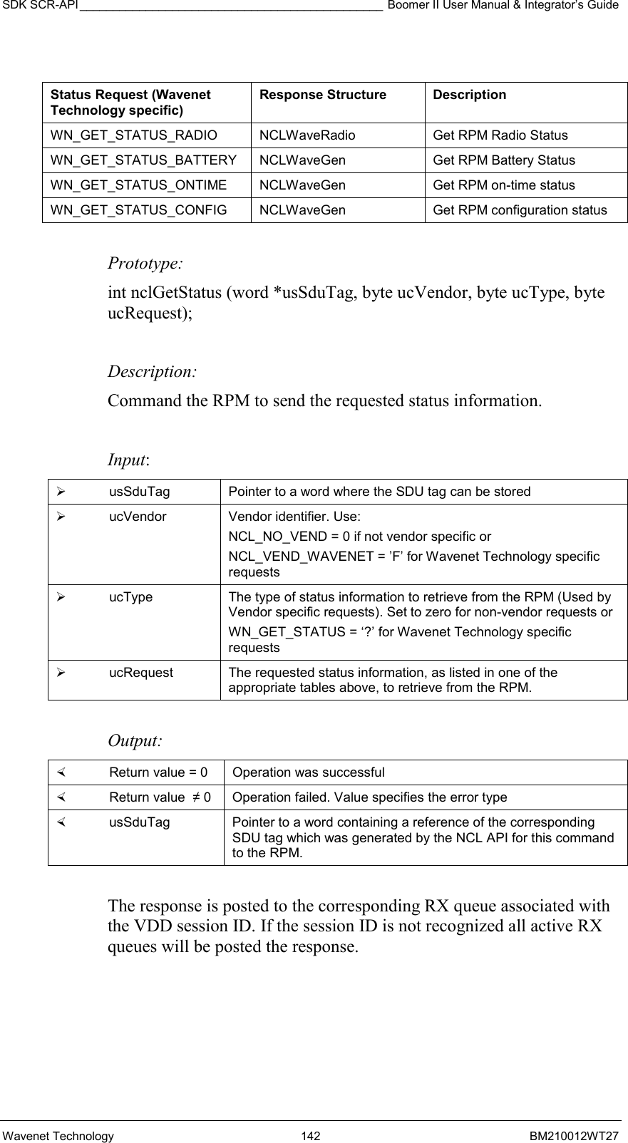
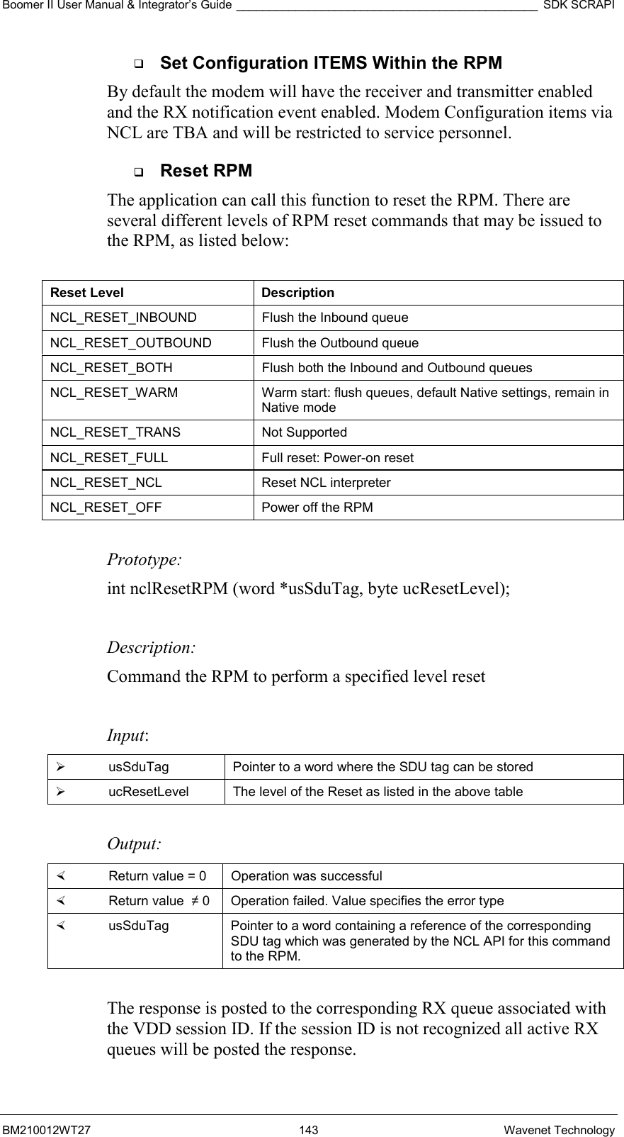
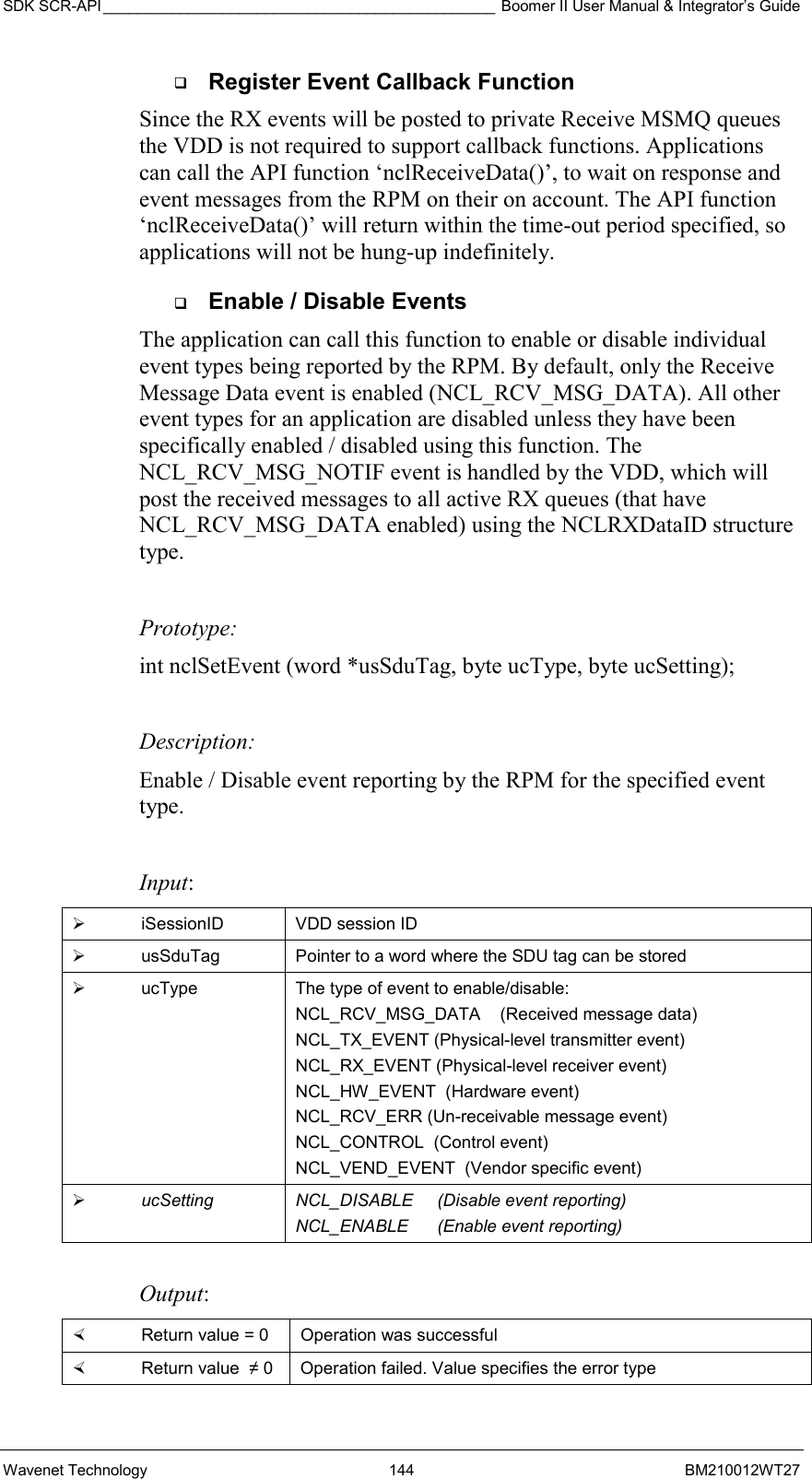
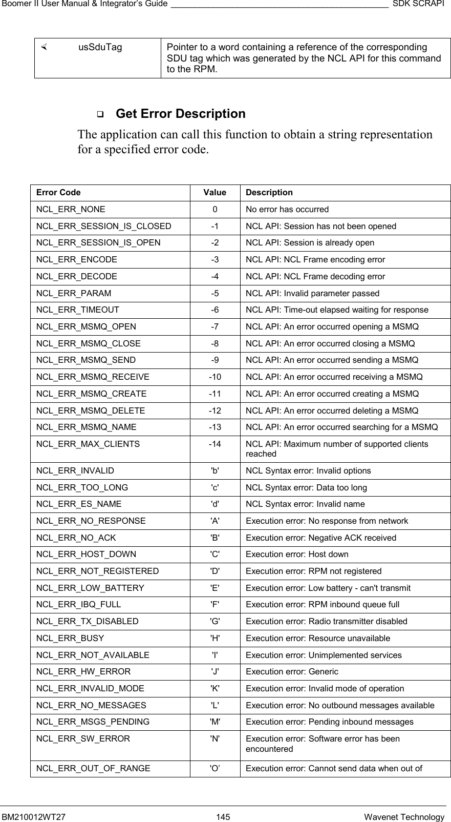
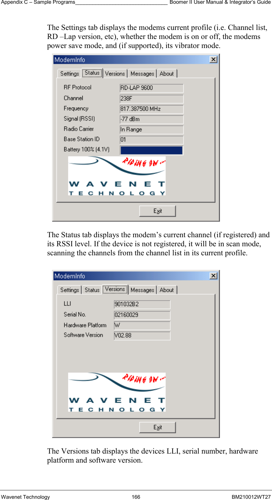
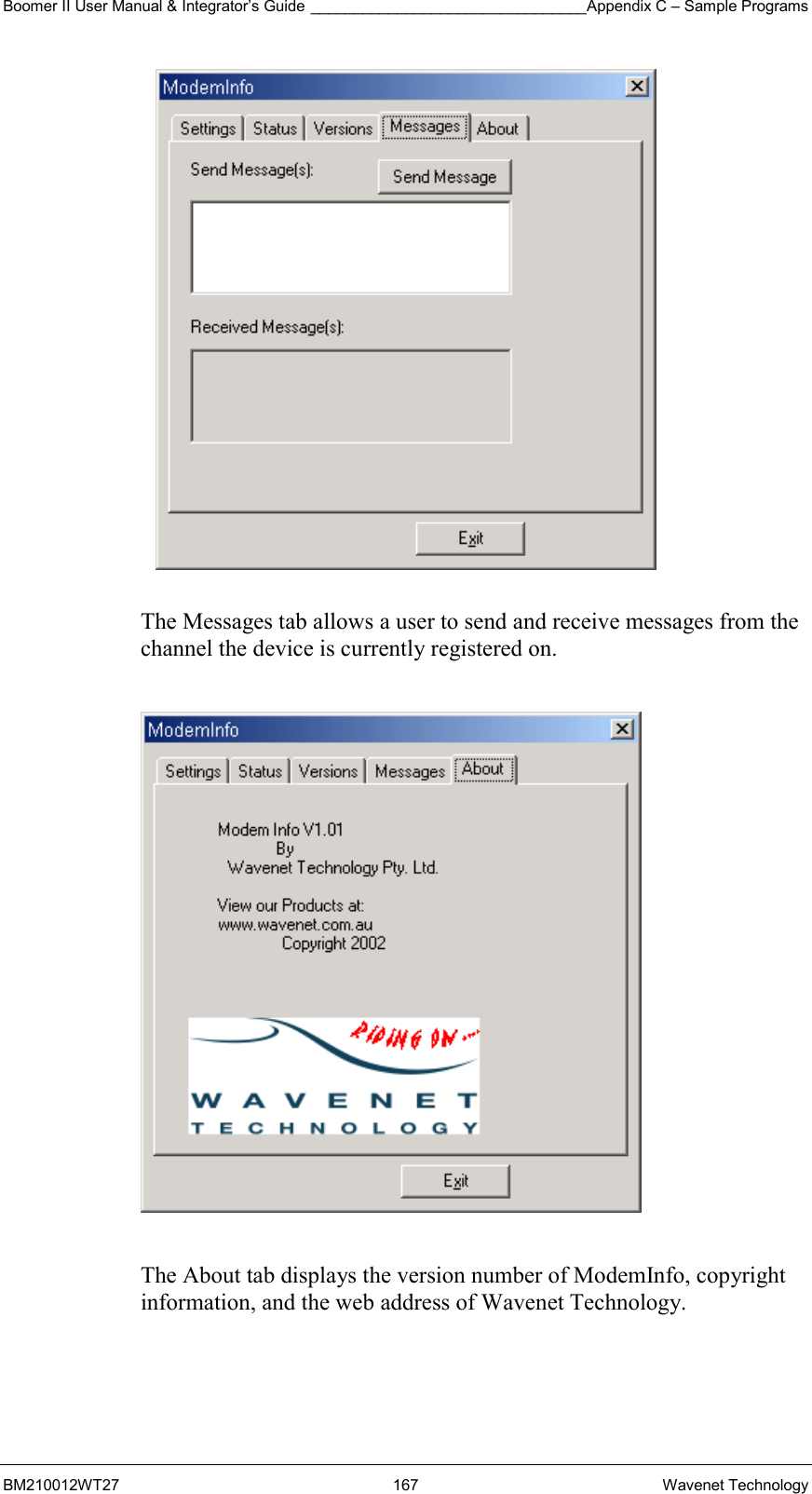
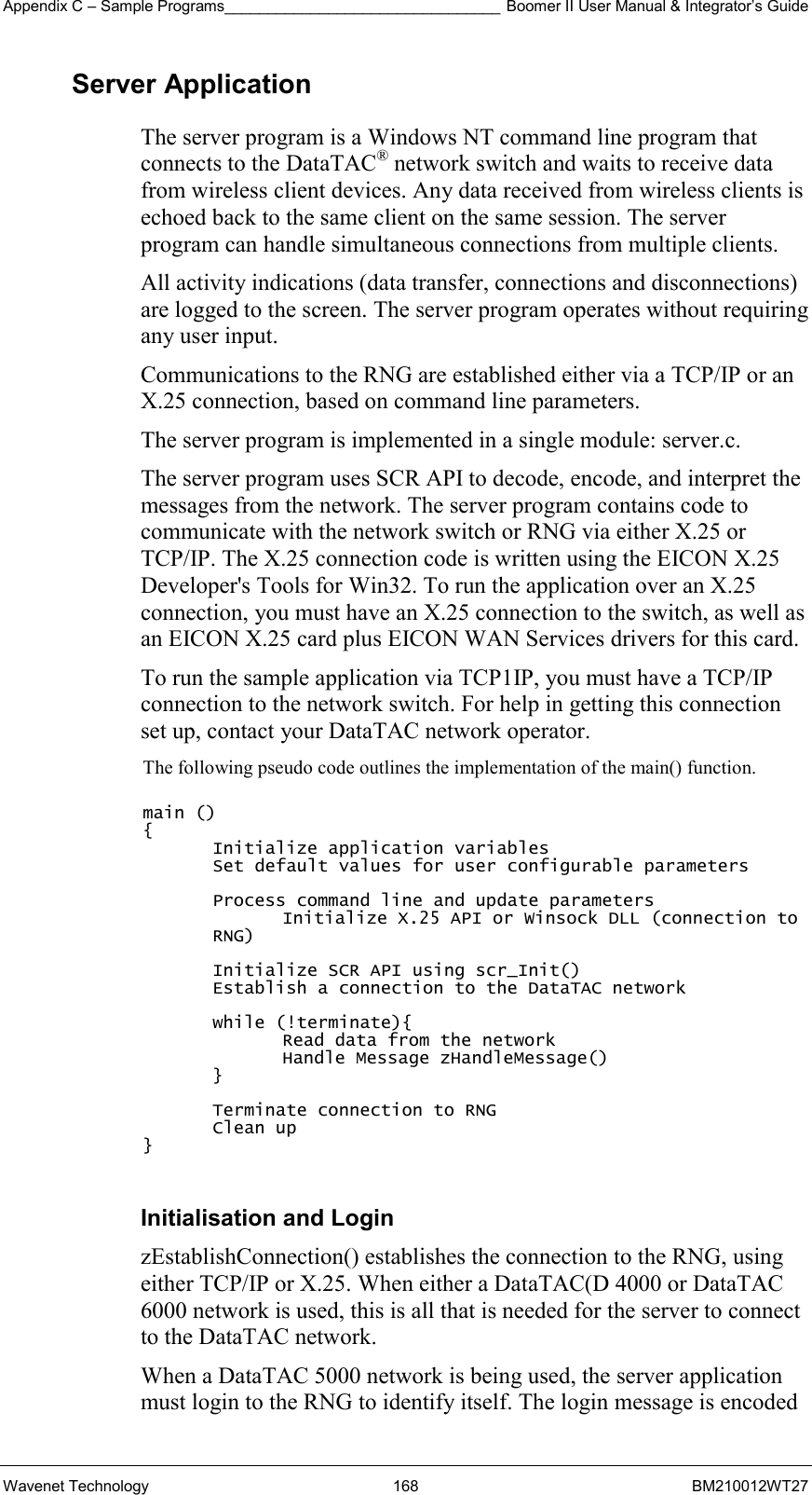
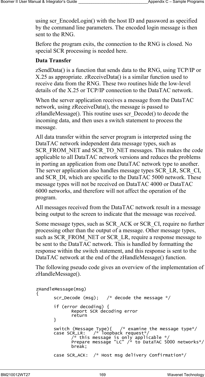
Wavenet Technology BM29001 Wireless OEM Modem Module User Manual Boomer II Integrators Guide

Wavenet Technology Pty Ltd. Wireless OEM Modem Module Boomer II Integrators Guide

Contents

Revised User Manual
          Boomer II OEM Modem Module User Manual and Integrator’s Guide    November 2002

  © Wavenet Technology Pty Ltd ACN 079 965 003  Publication No. BM210012WT27  Published November 2002    This publication is copyright and no part may be reproduced or copied without the prior consent of:  Wavenet Technology Pty Ltd. 140 Burswood Rd Burswood, 6100 Western Australia  Telephone:  +61 8 9262 0200 Facsimile:  +61 8 9355 5622 E-mail:   wavenet@wavenet.com.au Web Site:  www.wavenet.com.au  This manual is intended to be used for the operation of Wavenet Technology equipment. Performance figures quoted are typical values and subject to normal manufacturing and service tolerances.  Wavenet Technology Pty Ltd reserves the right to alter, without notice, the equipment, software or specification to meet technological advancement.  Microsoft, Windows and the Windows logo are registered trademarks or trademarks of Microsoft Corporation in the United States and other countries. Other product and company names herein may be the trademarks of their respective owners.  Whilst every precaution has been taken in the preparation of this document, neither Wavenet Technology Pty Ltd nor any of its representatives shall have any liability to any person or entity with respect to any liability, loss or damage caused or alleged to be caused directly or indirectly by the information contained in this book.  Published by Wavenet Technology Pty Ltd.   This device has not been authorized as required by the rules of the Federal Communications Commission (FCC). This device is not, and may not be, offered for sale or lease, or sold or leased within the USA, until authorization is obtained.   This product contains a transmitter approved under the FCC rules.  800MHz Modem Module FCC ID: PQS-BM28001 900MHz Modem Module FCC ID: PQS-BM29001  This device complies with Part 15 of the FCC rules. Operation is subject to the following two conditions: (1) This device may not cause harmful interference, and (2) This device must accept any interference received including interference that may cause undesired operation.
Boomer II User Manual & Integrator’s Guide __________________________________________________ Contents BM210012WT27 3 Wavenet Technology Contents Introduction ......................................................................................................9 Applications................................................................................................11 Compliance Statement ...............................................................................12 Information for Your Safety.........................................................................13 Host Requirements.....................................................................................14 The Integrator’s Task .....................................................................................15 Plan the Product and Create the Design ....................................................16 Develop a Usage Model .........................................................................16 Develop a Message Model .....................................................................16 Define a Service Strategy .......................................................................17 Diagnostic Capabilities ...........................................................................18 Customer Problem Isolation....................................................................18 End User Support ...................................................................................18 Investigate and Obtain Regulatory Approval ..........................................18 Develop and Validate the Hardware...........................................................19 Design the Hardware Platform................................................................19 Consider Power Supply Options.............................................................19 Select the Source Antenna .....................................................................19 Set Up a Development Test Environment...............................................19 Develop Supporting Applications Software.................................................20 Select a Communications Model ............................................................20 Develop End-to-End Applications Software ............................................20 Test and Approve the Product....................................................................20 Perform EMI and Desense Testing.........................................................20 Set Up a Final Test Environment............................................................21 Install and Field Test the Product ...........................................................21 Environmental Issues .................................................................................21 ESD Handling Precautions .....................................................................22 Regulatory Requirements...........................................................................23 Modem Only Certification........................................................................23 Full Product Certification.........................................................................23 Country Requirements............................................................................23 Air Interface Protocols ............................................................................27 Installing the Modem......................................................................................29 Mounting the Boomer II OEM Modem to Your Device................................30 Connecting the Data Interface Port ............................................................31 Data Interface Pin Descriptions ..............................................................33 Modem On/Off Control............................................................................34 Modem Reset Input ................................................................................35
Contents __________________________________________________ Boomer II User Manual & Integrator’s Guide Wavenet Technology  4  BM210012WT27 Serial Communications Interface ............................................................35 Status Input / Output lines ......................................................................37 LED Indicators ........................................................................................38 LED Output Lines ...................................................................................39 Selecting & Positioning the Antenna ..........................................................40 Antenna Safety .......................................................................................40 Mobile and Portable Devices ..................................................................40 Selecting an Antenna..............................................................................42 Connecting the Antenna .........................................................................42 Positioning the Antenna..........................................................................43 Source Based Time Averaging Function ................................................43 Supplying Power ........................................................................................45 Ratings ...................................................................................................45 Management...........................................................................................45 Conservation...........................................................................................46 Power Save Protocol ..............................................................................46 Power Profile ..........................................................................................47 Power Control.........................................................................................48 Power-Up Sequence...............................................................................48 Power Down Sequence ..........................................................................50 Batteries .................................................................................................51 Applying Battery Technologies ...............................................................53 Battery Recharging.................................................................................54 Plug-in Supplies......................................................................................54 Automotive Supplies ...............................................................................54 Environmental Considerations................................................................54 Using the Modem Test Jig .............................................................................55 Features .....................................................................................................55 Updates......................................................................................................55 Exploring the Boomer II Test Jig ................................................................56 Initial Calibration.........................................................................................59 Set Up ........................................................................................................59 RSUSER ....................................................................................................61 Operations ..............................................................................................61 Using RSUSER.......................................................................................62 Hot Key Descriptions ..............................................................................62 Reprogramming Modems .......................................................................66 Testing ...........................................................................................................67 Hardware Integration..................................................................................67 Enabler Functions...................................................................................67 Specific Tests .........................................................................................67
Boomer II User Manual & Integrator’s Guide __________________________________________________ Contents BM210012WT27 5 Wavenet Technology Desense and EMI.......................................................................................68 Regulatory Compliance ..............................................................................69 Application Software...................................................................................70 Software Driver Configuration.................................................................70 Network Configuration ............................................................................70 Final Assembly...........................................................................................70 End User Problem Resolution ....................................................................70 OEM Service Depot Repair ........................................................................71 Desense.........................................................................................................73 Noise Sources............................................................................................74 Receiver Susceptibilities.............................................................................74 Measurement Techniques..........................................................................74 Alternate Measurement Method .................................................................75 Methods of Controlling Emissions ..............................................................76 Shielding Approach.................................................................................76 Alternate EMI Reduction Methods ..........................................................77 RF Network Issues .....................................................................................78 Antenna......................................................................................................79 Field Strengths from the Antenna ...........................................................79 Antenna Interactions...............................................................................79 Desense Summary.....................................................................................79 Application Development ...............................................................................81 Roaming Issues..........................................................................................82 Roaming Requirements ..........................................................................82 Inbound SDU Failures ............................................................................84 Outbound SDU Failure ...........................................................................85 Loss of Network Contact.........................................................................85 Power Management ...................................................................................86 Power Save Mode ..................................................................................86 On/Off upon User Demand .....................................................................86 Radio On/Off on Application Command..................................................87 Battery Life Considerations.....................................................................87 Power Save Protocol ..............................................................................87 Wireless Data Systems Considerations .....................................................88 Application Efficiency..............................................................................88 Large Message Transfer.........................................................................88 Message Transit Time ............................................................................89 Message Routing and Migration ....................................................................91 Message Routing....................................................................................91 Network Link Layers ...............................................................................92
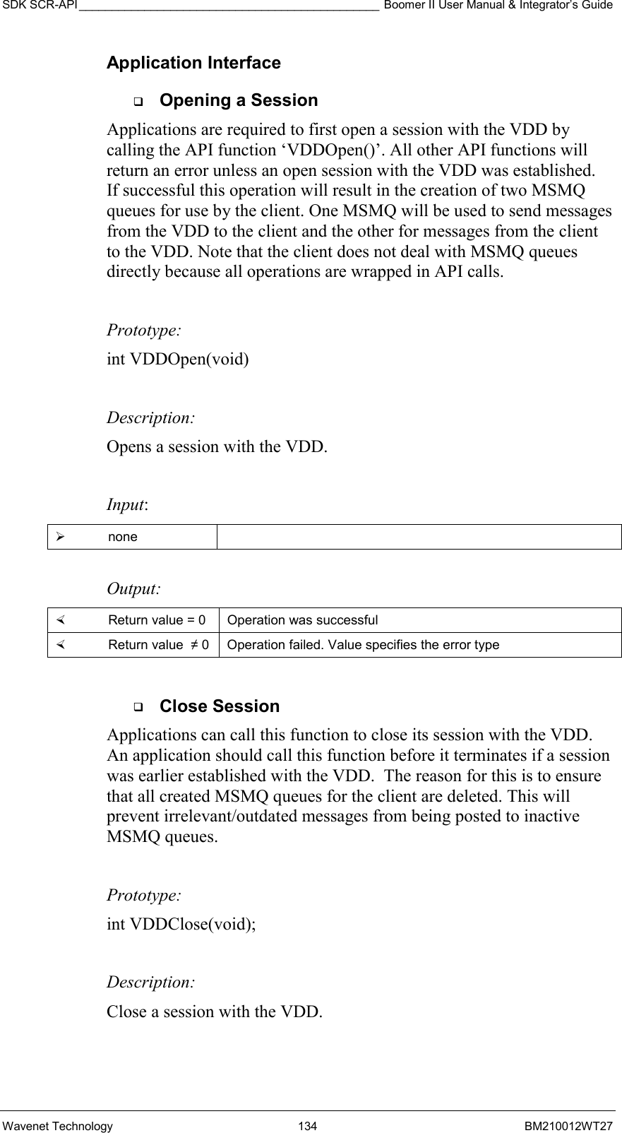
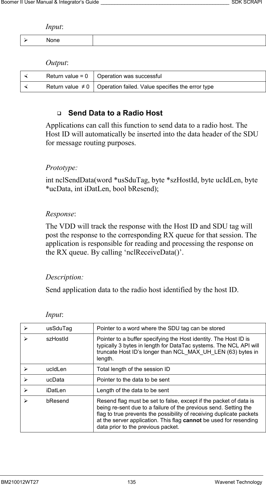
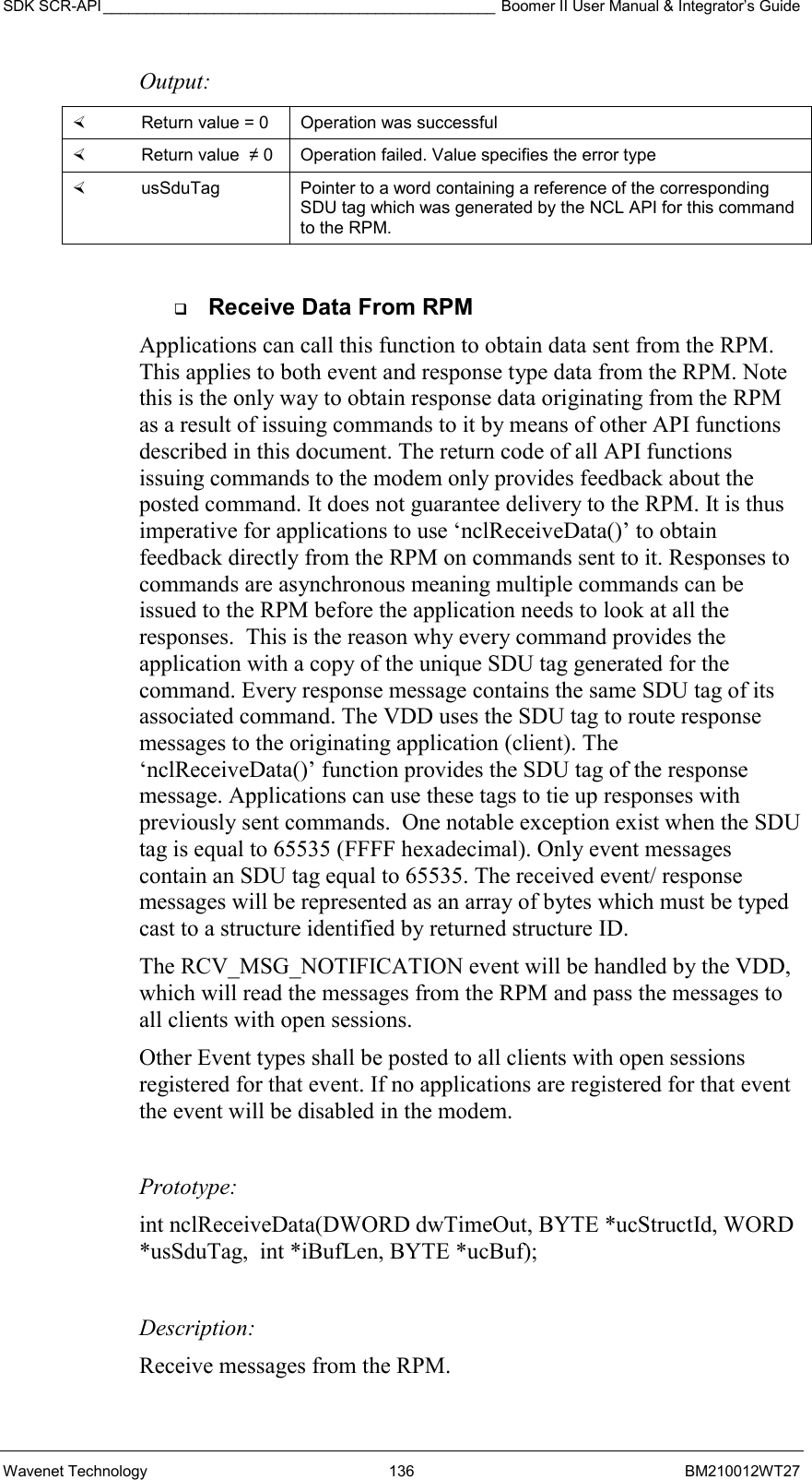
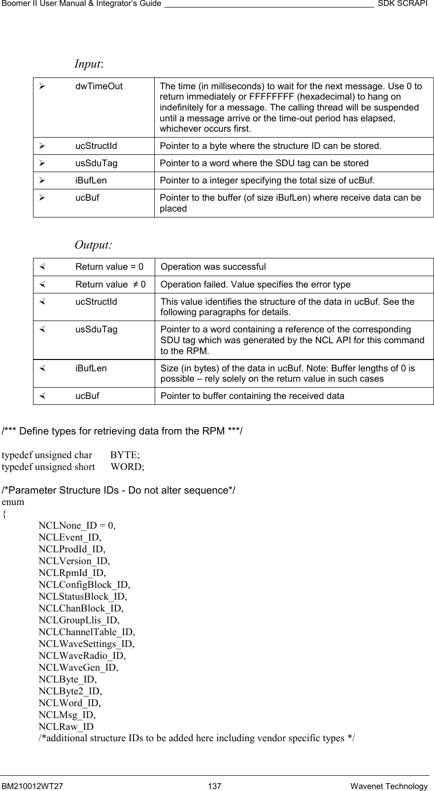
Contents __________________________________________________ Boomer II User Manual & Integrator’s Guide Wavenet Technology  6  BM210012WT27 Standard Context Routing (SCR) ...............................................................93 SCR Message Types..............................................................................94 Highlights of SCR Differences ................................................................94 SCR Header Charts ...................................................................................98 Host Request Message Header Fields ...................................................99 Host Confirmation Message Header Fields ..........................................101 Mobile Information Message Header Fields..........................................103 DataTAC Messaging (DM) .......................................................................105 DM Message Types..............................................................................105 Highlights of DM Differences ................................................................105 DM Header Charts ...................................................................................106 Message Generate Header Fields........................................................106 Receive Header Fields .........................................................................108 Host Messaging (HM)...............................................................................110 Other Development Issues.......................................................................110 Localizing an Application ......................................................................110 Testing an Application ..........................................................................111 Appendix A - NCL Interface .........................................................................113 Generic NCL (Native Mode) .....................................................................113  Command SDUs (CMND, ASCII A)...............................................113  Event Report SDUs (EVENT, ASCII B) .........................................115  Response Status SDUs (RESP, ASCII C).....................................116 Wavenet Specific NCL Extensions...........................................................118  GET STATUS COMMANDS:.........................................................118  Generic set RPM Configuration command type 1 (WN_SET_PARAM):.............................................................................122  Generic set RPM Configuration command type 2..........................125 Generic get RPM Configuration command (WN_GET_PARAM):.........126  NCL Label Values..........................................................................127 Appendix B - Software Development Kit ......................................................129 SDK Contents...........................................................................................129 System Requirements ..............................................................................131 SDK Software Architecture.......................................................................131 NCL Application Programmer’s Interface .................................................131 Implementation .....................................................................................131 Logical Architecture ..............................................................................132 Application Interface .............................................................................134 SCR Application Programmer’s Interface.................................................149 Implementation .....................................................................................150 SCR Structures.....................................................................................150 SCR Functions......................................................................................154
Boomer II User Manual & Integrator’s Guide __________________________________________________ Contents BM210012WT27 7 Wavenet Technology Appendix C – Sample programs ..................................................................165 Client Application......................................................................................165 Server Application ....................................................................................168 Initialisation and Login ..........................................................................168 Appendix D - Wavenet Application Loader ..................................................171 Updating Application Loader Software on Your Modem...........................171 Troubleshooting........................................................................................173 Appendix E - Numeric Conversion Chart .....................................................175 Appendix F - Specifications .........................................................................177 Appendix H - Glossary .................................................................................179
Contents __________________________________________________ Boomer II User Manual & Integrator’s Guide Wavenet Technology  8  BM210012WT27
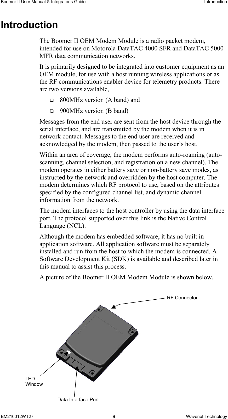
Boomer II User Manual & Integrator’s Guide ________________________________________________ Introduction BM210012WT27 9 Wavenet Technology Introduction The Boomer II OEM Modem Module is a radio packet modem, intended for use on Motorola DataTAC 4000 SFR and DataTAC 5000 MFR data communication networks. It is primarily designed to be integrated into customer equipment as an OEM module, for use with a host running wireless applications or as the RF communications enabler device for telemetry products. There are two versions available,    800MHz version (A band) and    900MHz version (B band) Messages from the end user are sent from the host device through the serial interface, and are transmitted by the modem when it is in network contact. Messages to the end user are received and acknowledged by the modem, then passed to the user’s host. Within an area of coverage, the modem performs auto-roaming (auto-scanning, channel selection, and registration on a new channel). The modem operates in either battery save or non-battery save modes, as instructed by the network and overridden by the host computer. The modem determines which RF protocol to use, based on the attributes specified by the configured channel list, and dynamic channel information from the network. The modem interfaces to the host controller by using the data interface port. The protocol supported over this link is the Native Control Language (NCL). Although the modem has embedded software, it has no built in application software. All application software must be separately installed and run from the host to which the modem is connected. A Software Development Kit (SDK) is available and described later in this manual to assist this process. A picture of the Boomer II OEM Modem Module is shown below.   LED Window Data Interface PortRF Connector
Introduction ________________________________________________ Boomer II User Manual & Integrator’s Guide Wavenet Technology  10  BM210012WT27  This manual contains the following sections: Section 1:  Introduction Section 2:  The Integrator’s Task Section 3:  Installing the Modem Section 4:  Modem Test Jig Section 5:  Testing Section 6:  Desense Section 7:  Application Development  Section 8:  Message Routing and Migration  In addition there is very useful reference information contained in the numerous Appendices which the reader may like to scan.  Features The Boomer II OEM Modem is approximately the size of a credit card and just 9mm thick. The modem is easily connected to many other devices and can be incorporated into a variety of package formats. The modem has a TTL serial port. The Boomer II OEM Modem has the following features:   Serial communications interface port (TTL level)  running an NCL protocol   Indicator lights shows the status of the network coverage and power supply   Four configurable digital input/output lines for external control/monitoring   Software configurable RF calibration adjustments to suit specific networks   High sensitivity reception   Small footprint and low profile design    Low-voltage and low standby current consumption for battery based products   Auto-wake up of host on incoming messages   Roaming capabilities as used in DataTAC system   Modem is always online using the DataTAC network   Easy to install, service and update
Boomer II User Manual & Integrator’s Guide ________________________________________________ Introduction BM210012WT27 11 Wavenet Technology Applications Suitable devices in which the Boomer II OEM Modem can be used include the following applications: Meter Reading The modem can be used to read billing information from intelligent electrical meters and basic disc meters. Data is transmitted wirelessly through a radio network to billing computers.  Point of Sale The modem can perform handshaking and complete verification of all data transmitted through the wireless network whilst providing convenient operator mobility such as open air events or conferences. Vending Machines Vending machines can also utilise radio data technology. Many machines already transmit usage and refill requirements to company head offices via standard telephone lines. Radio modems allow vending machines to be placed in areas with poor access to telecommunications infrastructure, providing a cost-effective alternative to installing new telephone lines. On refilling, only the required refills will be despatched to the required sites maximising truck carrying capacity and consequently efficiency.  Alarm Detection Conventional telephone wire connections are slow to dial out and can burn before the emergency call can be placed. Laws in many states and countries require businesses to have an on-line dial out fire alarm system. The Boomer II OEM Modem offers a real solution to this problem. Parking, Buses and Ticketing Ticketing machines are being be converted to cashless operation. The Boomer II OEM Modem is the best alternative to facilitate the introduction of this cashless technology.
Introduction ________________________________________________ Boomer II User Manual & Integrator’s Guide Wavenet Technology  12  BM210012WT27 Compliance Statement This device has not been authorized as required by the rules of the Federal Communications Commission (FCC). This device is not, and may not be, offered for sale or lease, or sold or leased within the USA, until authorization is obtained.   The Wavenet Boomer-II OEM Modem Module has been tested and found to comply with the limits for a class B digital device, pursuant to Part 15 of the FCC rules. These limits are designed to provide reasonable protection against harmful interference in a residential installation.  Output is specified at the antenna terminal of this module. This modular transmitter is only approved for OEM integration into final products that satisfy mobile operating requirements of 2.1091 of the FCC rules. The final product and its antenna must operate with a minimum separation distance of 20 cm or more from all persons using the antenna with maximum average gain not exceeding 1 dBi to satisfy MPE compliance. Separate approval is required for this module to operate in portable products with respect to 2.1093 of FCC rules. Wavenet has obtained certificates of Technical Acceptability for use in Canada in accordance with the Radio Standards Procedure RSP-100 and Radio Standards Specification RSS119, Issue 3. This equipment generates, uses and can radiate radio frequency energy and, if not installed and used in accordance with the manufacturer’s instructions, may cause interference harmful to radio communications. There is no guarantee however, that interference will not occur in a particular installation. If this equipment does cause harmful interference to radio or television reception, which can be determined by turning the equipment off and on, the user is encouraged to try to correct the interference by one or more of the following measures:   Reorient or relocate the receiving antenna.   Increase the separation between the equipment and receiver.   Connect the equipment into an outlet on a circuit different from that to which the receiver is connected.   Consult your supplier or an experienced radio/TV technician for assistance. Warning:  Changes or modifications to this unit not expressly approved by the party responsible for compliance could void the user’s authority to operate this equipment.
Boomer II User Manual & Integrator’s Guide ________________________________________________ Introduction BM210012WT27 13 Wavenet Technology Information for Your Safety Please read these safety instructions and the operation instructions provided in this manual before operating the Boomer II OEM Modem. Safe Use Switch the modem off in areas where radio devices are forbidden, or when it may cause interference or danger. For example, fuel depots (fuel storage and distribution areas), chemical plants, and locations in which hazardous or combustible gases may be present and where blasting operations are in progress. Do not use the modem in an aircraft. Such use may affect aircraft instrumentation, communication and performance and may be illegal. Be aware that the modem may interfere with the functionality of inadequately protected medical devices, including pacemakers. Additionally, the effect of the radio signals from the modem on other electronic systems, including those in your car (such as electronic fuel-injection systems, electronic anti-skid braking systems, and electronic cruise-control systems) may affect the operation of these systems, which should be verified before use in the applications Do not place the modem on an unstable surface. It may fall and damage the equipment. Never push objects of any kind into the modem through openings as they may short out parts that could result in a fire or electrical shock. Never spill liquid of any kind on the modem. Do not use the modem near water (for example near a bathtub or sink, in a wet basement, near a swimming pool etc.). The modem should be situated away from heat sources. Disconnect the modem from the power source before cleaning. Do not use liquid or aerosol cleaners. Use a damp cloth to clean the unit. Disconnect the modem from the power source and contact your supplier if:   Liquid has been spilled or objects have fallen onto the modem.   It has been exposed to rain or water.   It has been dropped or damaged in any way.   It does not operate normally by following the instructions contained in this manual.   It exhibits a distinct change in performance. Failure to observe all these instructions will void the limited warranty.
Introduction ________________________________________________ Boomer II User Manual & Integrator’s Guide Wavenet Technology  14  BM210012WT27 Integrator Developers Kit Wavenet has made available an Integrator Developers Kit which contains all the components necessary to get an evaluation and development platform up and running in the shortest possible time. The Developers Kit contains the following components   Boomer-II Modem Test Jig   Power Cable   RS-232 Serial Cable   MMCX to SMA antenna adaptor cable   800 MHz (blue tip) or 900 MHz (red tip) ¼ wave whip antenna   Flexible Printed Circuit (FPC) connector strips (5 pieces)   FPC connectors (5 pieces)   CDROM containing Software Developers Kit (SDK) and Integrator's Guide/User Manual Host Requirements The minimum system requirements of the host interface PC in order to utilise the Integrator Developers Kit are:   Intel compatible Pentium computer or higher   Windows 98 or later   16MB RAM (memory) minimum, 32MB recommended   1MB available hard disk space   9-pin serial Port using a 16550 UART   3.5-inch Disk Drive   CD-ROM drive
Boomer II User Manual & Integrator’s Guide ____________________________________________ Integrator’s Task BM210012WT27 15 Wavenet Technology The Integrator’s Task This section provides background information and points out the objectives and tasks of reaching the goal of a successful implementation. Areas of Focus  Benefits Serial Port  Pass-Through Capability   Enables modem diagnostics and software upgrades without the need to disassemble the host device or terminal.  Understanding RF Design    Provides the required network coverage.    Sets end-user performance criteria.    Reduces risk of costly redesigns. Software & Hardware    Provides reliable operation through a state-of-the-art functional interface.    Helps ensure longer service life and fewer field returns.  Because wireless data communication technologies are usually described using a unique variety of jargon, buzzwords, and technical details, it is sometimes hard to know where to start. You may also have difficulty evaluating this technical information when you find it. As an OEM integrator, you must accurately choose where and how a wireless technology will facilitate communication for your application. You will also have to evaluate which technical considerations will give your product an edge over the competition. To successfully integrate the Boomer II OEM wireless modem into the host platform, you must perform the following tasks:   Plan the product and create the design   Develop and validate the hardware   Develop supporting applications software   Test and approve the product As you review these tasks, allow sufficient time for such required activities as the regulatory approval process. Identify critical path activities up front.
Integrator’s Task ____________________________________________ Boomer II User Manual & Integrator’s Guide Wavenet Technology  16  BM210012WT27 Plan the Product and Create the Design To plan the product and create the design, perform the following steps:   Develop a usage model.   Develop a message model.   Define a service strategy.   Investigate and obtain regulatory approval. Develop a Usage Model The usage model answers the question, “How will the end product be used (portable or mobile; 8 hours, 7 days a week; and so on)?” Perhaps the most important enabler of success is a clear determination of how the final product is to be used. This steers the development process, because all design considerations drive toward meeting the needs of the final user. For example, design issues related to a mobile device, such as alternator noise and vibration, are completely different from considerations required for a fixed-point telemetry application powered by a solar panel. Defining what is and what is not important to the end user helps to make the critical engineering trade-off decisions that are inevitable in every product design. Develop a Message Model The message model defines how many messages are sent/received and how often. To create the message model, determine how much and how often data will be sent in each of the uplink (terminal to network) and downlink (network to terminal) directions. Answer the question, “Is there a requirement for the terminal to be on and able to receive 8 hours a day, or does the user turn the unit on only when making a query to the host system?” The answer has a direct bearing on the battery size and capacity requirement for powering the device. The amount of data sent and received is relevant in calculating the cost of airtime and deciding on which type of network connection to use. In short, the message model is required source data for making many engineering design decisions, especially in calculating such values as sleep time versus wake time and in determining battery capacity requirements. For additional information, refer to section “Message Traffic Model” on page 47. The typical approach to creating the model is to define the peak and average network throughput requirements based on input from the user. Wavenet Technology is able to provide current consumption figures for each of the various modes of operation (receive and transmit, for example) and explain the functionality of the network Power Save protocol. The network throughput of the host device depends on many factors in addition to the raw throughput of the radio channel. For example, in addition to the overhead involved in forward error correction and
Boomer II User Manual & Integrator’s Guide ____________________________________________ Integrator’s Task BM210012WT27 17 Wavenet Technology support for packet headers, the number of active users on a shared RF channel can directly affect network throughput. Define a Service Strategy The service strategy determines whether the integrated modem is the cause of a user’s problem and sets a policy for keeping the end user operational during repair. The service strategy must consider all potential service situations and evaluate them in light of the usage model.  To ensure that a final product can be efficiently serviced, you must design for service-ability early in the development process. At a minimum, you must develop a functional service strategy that contains a well-considered procedure for performing unit-level screening. The test must primarily determine whether a fault lies with the modem or with the product. The test must also screen for network problems and human error. Wavenet provides an evaluation board (a standalone test jig) and various software test utilities. The evaluation board provides a mounting platform and electrical interface to the modem. Testing is performed much more efficiently while the modem is still integrated within the host device or terminal, whether for a factory end-of-line test or while at the user’s site. For your product to allow integrated testing of the modem, you are required to provide modem pass-through mode and utilise Wavenet RSUSER software. See “End User Problem Resolution” on page 70. Without pass-through, the modem must be mounted on the evaluation board for diagnostics and troubleshooting. Pass-through mode also allows for modem software upgrades. A thoroughly developed OEM serviceability plan typically includes a needs assessment for developing software utilities that can assist in identifying communication problems between the host device and the modem and between the modem and the RF network. These utilities must be able to send commands to the modem, evaluate the modem responses, perform network connectivity testing, and verify data communication with the network. The utilities can be developed using NCL. This link-layer protocol set provides the capability to monitor and evaluate the modem’s operating condition and all communications to and from the network host. NCL 1.2 uses a command-response functional model. First, the network host asks for modem status and status of network connectivity. The modem then responds with its status and the state of network connection management. Such a software utility is essential for field service engineers and shop technicians to diagnose problems with the product and to troubleshoot a problem to a failed assembly or mismanaged communication link.
Integrator’s Task ____________________________________________ Boomer II User Manual & Integrator’s Guide Wavenet Technology  18  BM210012WT27 Diagnostic Capabilities To provide modem diagnostics, there are three LEDs on the modem itself. When the unit is first powered up it goes through its own self test and the status is reflected in the visual status of the LEDs. Customer Problem Isolation When application-visible problems are discovered in the field, you must isolate the source of the problem. Is it the network, wireless modem, or the host product that is not working as expected? Often it can be a user’s misunderstanding of how to use the product. Regardless, remote troubleshooting is essential to reducing the number of returned products and lowering service costs, particularly if the host must be disassembled for removal of the modem. Wavenet recommends that your product application (both at the terminal and host ends) incorporate sufficient problem diagnostic software to determine the cause of the problem remotely. Often, the best approach is to incorporate progressively deeper loop back tests to determine the point at which the communication link fails. As stated elsewhere, you need to make this remote diagnostic functionality be part of your standard software load.  End User Support You have two choices in dealing with an integrated modem that needs to be swapped out and returned for service:   Decommission the modem and re-use the LLI   Replace the modem If you decommission the modem Id (the LLI) from the defective unit and transfer it to a replacement unit, the user and the network operator are unaffected. This can only be done by an authorized Wavenet service centre with the appropriate permissions and authority. If you simply swap the defective unit with a replacement, the user must notify the network operator.  Investigate and Obtain Regulatory Approval Most countries where the final product will be sold currently require approval from the local government regulatory body. It is your responsibility to investigate and obtain the proper regulatory approval and certification for each country in which the product is sold.  Regulatory issues are discussed in more detail in “Regulatory Requirements” on page 23. In addition, see “Regulatory Compliance” on page 69.
Boomer II User Manual & Integrator’s Guide ____________________________________________ Integrator’s Task BM210012WT27 19 Wavenet Technology Develop and Validate the Hardware To develop and validate the hardware, perform the following steps:   Design the hardware platform   Consider power supply options   Select the source antenna   Set up a development test environment Design the Hardware Platform Integrating a wireless modem into a hardware design requires many steps. Here again, the usage and message models are necessary to calculate issues such as battery size, heat dissipation, isolation from EMI, and physical mounting of the unit to ensure proper grounding. Hardware design is your responsibility. Wavenet can provide recommendations where applicable and may also assist with verification of EMI-caused desense once the modem is integrated into the host.  Consider Power Supply Options Power supply requirements vary according to the usage and message models. Beyond accounting for the current drain of the modem in its various operating modes, consider ripple and noise on the power lines, and the ability to supply sufficient instantaneous current to allow proper operation of the transmitter. Also, ensure that the power supply can accommodate the highest power consumption under transmit conditions and that the voltage does not fall below the minimum levels at the modem terminals. (Remember voltage drops can occur in the interconnectivity wiring and this must be kept as short as possible.) Together, these requirements define the type and size of power supply to use with the modem. These issues are discussed in more detail in the sections “Power Management” on page 45 and “Batteries” on page 51. Important: Avoid use of switching power supplies. They can easily cause RF noise that desenses the modem. Select the Source Antenna The ERP (Effective Radiated Power) generated by the antenna must meet the requirements of the various network operators. Consider these network requirements when you select an antenna system. See “Connecting & Positioning the Antenna” on page 40.  Set Up a Development Test Environment A number of development test aids are available to assist in hardware and applications development. Wavenet can provide both the modem hardware and an evaluation board. The evaluation board is a specially developed circuit board with test points and jumper switches. The
Integrator’s Task ____________________________________________ Boomer II User Manual & Integrator’s Guide Wavenet Technology  20  BM210012WT27 evaluation board allows for maximum flexibility in accessing and controlling connections into and out of the modem. Wavenet also provides various software utilities that can help in performing development tests. See “Testing” on page 67.  Supplementing the test environment, the network operator sometimes provides a live development network, one separate from the production network on which you can develop and test your application. Develop Supporting Applications Software To develop supporting applications software, perform the following steps:   Select a communications model   Develop end-to-end applications software Select a Communications Model Select a communications model. Most vertical market applications use fleet host (SCR) connections to a single host, whereas horizontal applications typically use a gateway to allow connection to the Internet or other external networks. See “Air Interface Protocols” on page 27. Develop End-to-End Applications Software In addition to coding the product-specific features for your application, you are urged to incorporate RF-specific reporting and monitoring features, such as received signal strength (RSSI), channel quality, and in-range/out-of-range conditions. Many applications track the number of packets sent and received and the various events and status indicators available from the modem. The Boomer II modem uses a packetised serial interface (Native Control Language 1.2) to allow the application to simultaneously monitor RF-related information and application-specific data.  Test and Approve the Product To test and approve the product, perform the following steps:   Perform EMI and desense testing   Set up a final test environment   Install and field test the product Perform EMI and Desense Testing Proper modem operation requires that you minimize EMI (electromagnetic interference) radiated from your product’s platform. Excess noise significantly reduces the wireless modem’s ability to receive, making the network less likely to be heard.
Boomer II User Manual & Integrator’s Guide ____________________________________________ Integrator’s Task BM210012WT27 21 Wavenet Technology Wavenet provides a test facility for measuring host emissions and subsequent modem desense of integrated host terminals. See “Desense and EMI” on page 68. In addition, see “Desense” on page 73. Set Up a Final Test Environment To ensure proper assembly of the final product (antenna properly connected, serial port operational, and so on), perform an end-to-end test that proves the final product can receive and transmit at the required signal levels. In locations where the final assembly test is performed within network coverage area, this test is relatively simple. But in locations where network coverage is not available, or for products to be shipped to another country, it is necessary to test by secondary means. The final assembly test must verify that all connections to the modem are made correctly. Testing on a network is not required. See “Final Assembly” on page 70, and “End User Problem Resolution” on page 70. Install and Field Test the Product When the product is shipped to a site, it is installed or mounted in a particular location, one that might restrict RF communications. The service question is whether the behaviour of a dysfunctional product is caused by poor coverage or a network service provider is down. To guarantee that the modem is located in an area of good coverage and that an end-to-end loop back message is possible, your product needs a software application to perform the test. Your most effective approach to field testing is to include an installation test procedure as part of your standard software load. See “Final Assembly” on page 70 and see “End User Problem Resolution” on page 70. Environmental Issues The Boomer II OEM modem is designed for a combination of easy serviceability and general ruggedness but are designed to be housed in a host device or terminal. The modem is tested to conform to the environmental levels (for example, industrial use specifications and PC card standards) that meet the intended applications of most integrators. If you need additional ruggedness and safety in your products, you must engineer the environmental characteristics of your host product to achieve a special safety rating. General Precautions   Minimise handling of static sensitive modules and components.   Wear a grounded anti static wrist strap while handling static sensitive components.   Do not bend or stress the modem in any way.
Integrator’s Task ____________________________________________ Boomer II User Manual & Integrator’s Guide Wavenet Technology  22  BM210012WT27   Reinsert connectors straight and evenly to avoid causing short and open circuits. ESD Handling Precautions The Boomer II OEM modem contains components sensitive to ESD (electrostatic discharge). For example, people experience up to 35kV ESD, typically while walking on a carpet in low humidity environments. In the same manner, many electronic components can be damaged by less than 1000 volts of ESD. Although the Boomer-II modem has been designed with a high level of ESD protection you should observe the following handling precautions when servicing host devices or terminals:   Always wear a conductive wrist strap.   Eliminate static generators (plastics, Styrofoam, and so on) in the work area.   Remove nylon or polyester jackets, roll up long sleeves, and remove or tie back loose hanging neckties.   Store and transport all static sensitive components in ESD protective containers.   Disconnect all power from the unit before ESD sensitive components are removed or inserted, unless noted.   Use a static safeguarded workstation, which can be set up by using an anti static kit. This kit typically includes a wrist strap, two ground cords, a static control table mat, and a static control floor mat. When anti static facilities are unavailable use the following techniques to minimize the chance of damaging the equipment:   Let the static sensitive component rest on a conductive surface when you are not holding it.   When setting down or picking up the static sensitive component, make skin contact with a conductive work surface first and maintain this contact while handling the component.   If possible, maintain relative humidity of 70-75% in development labs and service shops.
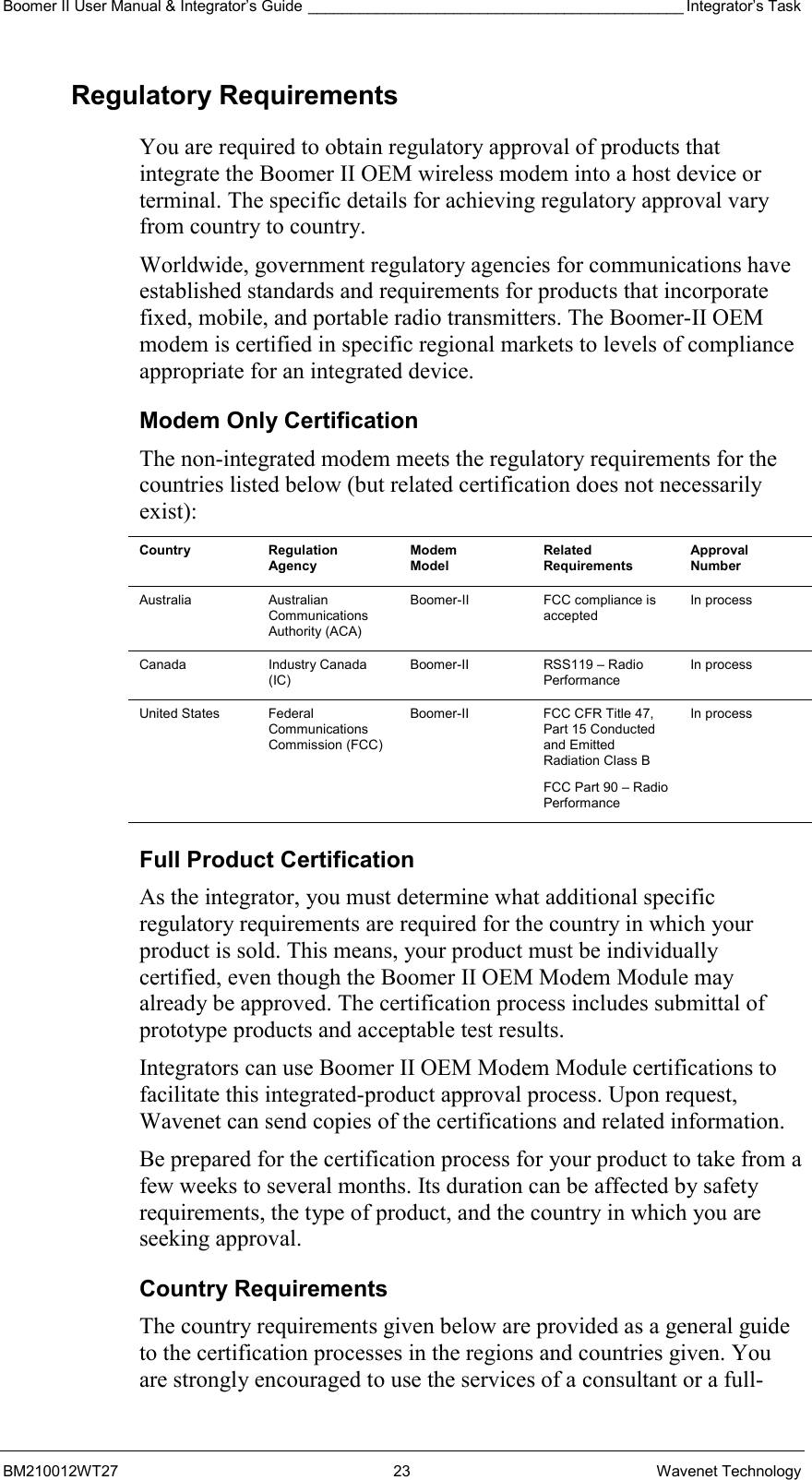
Boomer II User Manual & Integrator’s Guide ____________________________________________ Integrator’s Task BM210012WT27 23 Wavenet Technology Regulatory Requirements You are required to obtain regulatory approval of products that integrate the Boomer II OEM wireless modem into a host device or terminal. The specific details for achieving regulatory approval vary from country to country. Worldwide, government regulatory agencies for communications have established standards and requirements for products that incorporate fixed, mobile, and portable radio transmitters. The Boomer-II OEM modem is certified in specific regional markets to levels of compliance appropriate for an integrated device. Modem Only Certification The non-integrated modem meets the regulatory requirements for the countries listed below (but related certification does not necessarily exist): Country Regulation Agency Modem Model Related Requirements Approval Number Australia Australian Communications Authority (ACA) Boomer-II  FCC compliance is accepted In process Canada Industry Canada (IC) Boomer-II RSS119 – Radio Performance In process United States  Federal Communications Commission (FCC) Boomer-II  FCC CFR Title 47, Part 15 Conducted and Emitted Radiation Class B FCC Part 90 – Radio Performance In process Full Product Certification As the integrator, you must determine what additional specific regulatory requirements are required for the country in which your product is sold. This means, your product must be individually certified, even though the Boomer II OEM Modem Module may already be approved. The certification process includes submittal of prototype products and acceptable test results. Integrators can use Boomer II OEM Modem Module certifications to facilitate this integrated-product approval process. Upon request, Wavenet can send copies of the certifications and related information.  Be prepared for the certification process for your product to take from a few weeks to several months. Its duration can be affected by safety requirements, the type of product, and the country in which you are seeking approval. Country Requirements The country requirements given below are provided as a general guide to the certification processes in the regions and countries given. You are strongly encouraged to use the services of a consultant or a full-
Integrator’s Task ____________________________________________ Boomer II User Manual & Integrator’s Guide Wavenet Technology  24  BM210012WT27 service test house if you have limited expertise in meeting the regulatory requirements of a specific country. All certification tests must be made by a qualified laboratory to ensure that the equipment complies with the applicable technical standards. United States of America The Federal Communications Commission (FCC) requires application for certification of digital devices in accordance with CFR Title 47, Part 2 and Part 15. A Wavenet Boomer-II OEM Modem Module is part of a complete system and certain testing is necessary for the integrated product. FCC Part 15, Class A/B certification must be performed with the maximum configuration use and include all peripherals of the integrated product. The application for certification must refer to the approval data on file for the particular Boomer-II Modem Module, as shown in the following example. Include the following language in user documentation inserting the name of the integrated product in place of xxx below:  “The Wavenet Boomer-II OEM modem module is a subassembly of xxx and has FCC Identifier PQS-BM28001” (or PQS-BM29001 as appropriate) FCC Part 2 certification requires all integrated products to have routine environmental evaluation for radio-frequency (RF) exposure prior to equipment authorization or use in accordance with FCC rules 2.1091 and 2.1093 and FCC Guidelines for Human Exposure to Radio Frequency Electromagnetic Fields, OET Bulletin 65 and its Supplement C.  For “portable devices”, defined in accordance with FCC rules as transmitting devices designed to be used within 20 cm of the user body under normal operating conditions, Specific Absorption Rate (SAR) testing must be performed.  An exposure limit of 1.6 W/kg will apply to most OEM integrated applications. For “mobile or fixed devices”, defined as transmitting devices designed to be generally used such that a separation distance of at least 20 cm is maintained between the body of the user and the transmitting radiated structure, Maximum Permissible Exposure (MPE) limits may be used with field strength or power density limit of 0.54 mW/cm2 (at 806 MHz).  Wavenet submitted module specific information and test reports for generic MPE compliance. The antennae used for FCC certification were:   For the 800 MHz modem: Radiall/Larsen - Whip Standard ¼ wave SPWH20832 (maximum average gain 1dBi)   For the 900 MHz modem: Radiall/Larsen - Whip Standard ¼ wave SPWH20918 (maximum average gain 1dBi)
Boomer II User Manual & Integrator’s Guide ____________________________________________ Integrator’s Task BM210012WT27 25 Wavenet Technology If the Boomer-II OEM Modem Module is used in a mobile or fixed application and if the integrator uses one of the above antennae with an antenna lead length no shorter than 150mm, the MPE limits will not be exceeded. In this case, the following clause should be included in the installation and user documentation: "To satisfy FCC RF exposure requirements a separation distance of 20 cm or more should be maintained between the antenna of this device and persons during device operation. To ensure compliance, operations at closer than this distance is not recommended." If a different antenna is used to that which was tested by Wavenet for FCC approval, then the integrated product must be re-tested as a complete unit and submitted with its own FCC ID.   It is mandatory for portable integrated products such as handheld and body-worn devices to comply with FCC guidelines for Specific Absorption Rate (SAR) requirements. Refer to OET Bulletin 65 and Supplement C (June 2002). The submission should include end product information, end product SAR/MPE test report, and a reference to the Wavenet Boomer-II OEM Modem Module FCC ID for all other Part 90 requirements. It is a requirement for integrated product certification that you provide the following statement in user documentation: “Regulatory Notice of Compliance This equipment has been tested and found to comply within the limits for a Class B digital device, pursuant to Part 15 of the FCC Rules. These limits are designed to provide reasonable protection against harmful interference in a residential installation. This equipment generates, uses, and can radiate radio frequency energy and, if not installed and used in accordance with the instructions, may cause harmful interference to radio communications. However, there is no guarantee that interference will not occur in a particular installation. If this equipment does cause harmful interference to radio or television reception, which can be determined by turning the equipment off and on, the user is encouraged to try to correct the interference by one or more of the following measures:   Reorient or relocate the receiving antenna.   Increase the separation between the equipment and receiver.   Connect the equipment into an outlet on a circuit different from that to which the receiver is connected.   Consult the dealer or an experienced radio/TV technician for help.”
Integrator’s Task ____________________________________________ Boomer II User Manual & Integrator’s Guide Wavenet Technology  26  BM210012WT27 Labelling  The FCC requires the integrated product to be labelled as shown here: “This product contains a type-accepted transmitter approved under FCC ID: PQS-BM2xxxxx.” Refer to FCC CFR 47, Part 2, Subpart J for information on obtaining an FCC grantee code, FCC identifier requirements, label requirements, and other equipment authorisation procedures. The FCC does not permit use of an FCC identifier until a Grant of Equipment Authorisation is issued. If you display a device at a trade show before the FCC has issued a grant, the following statement must be prominently displayed: “This device has not been approved by the Federal Communications Commission. This device is not, and may not be, offered for sale or lease, sold or leased until the approval of the FCC has been obtained.” Canada Industry Canada (IC), formerly the Department of Communications, requires certification for all radio transceivers as either type-approved or technically accepted. If you do not make any physical or electrical changes to the Boomer II OEM modem and you add an antenna externally to your host product, you are not required to make a formal application to Industry Canada, because Boomer II OEM modems continue to be covered under the original Radio Equipment Certificate of Type Approval. Most of the tests required for FCC applications can be used for Industry Canada applications. IC requires additional tests, which distinguishes their certification process as unique. The Radio Standards Procedure RSP-100 describes the procedure for obtaining certification of radio equipment and labelling requirements. These documents are available upon request from Industry Canada in Ottawa. Labelling IC requires OEM products to be labelled as  109 BXXXX Where XXXX represents the number supplied to the OEM by IC.
Boomer II User Manual & Integrator’s Guide ____________________________________________ Integrator’s Task BM210012WT27 27 Wavenet Technology Air Interface Protocols Data exchange protocols transport data between the host device or terminal and the network. Within the radio portion of the network, between the device and the base station, specialized RF protocols (RD-LAP or MDC4800) carry the data. These radio protocols are typically transparent to wireless applications. The modem communicates over radio frequency channels using the RD-LAP 9.6, RD-LAP 19.2, or MDC 4800 protocols and an internal 800, or 900MHz radio to operate over 12.5 or 25kHz RF channels. The network-specific configuration is constant for all like devices on the network and includes the channel list and the system ID. The modem has dual protocol capability on DataTAC 4000 systems in the United States and Canada. The modem’s RF protocol is based on the attributes specified by the configured channel list, and dynamic channel information from the network. On DataTAC 5000 systems, only the RD-LAP protocol is supported. The modem performs auto-roaming (that is, auto-scanning, channel selection, and registration on a new channel). Battery-save operation (Power Save protocol) is supported within most DataTAC networks. RD-LAP Network Operation The RD-LAP 9.6 and 19.2 protocols are used by DataTAC 4000 and 5000 networks. The modem supports both continuously keyed, multiple channel (MFR) and intermittently keyed, SFR (single frequency reuse) network configurations, depending on the network type. The RD-LAP protocol specifications provide the reference RF protocol link-access procedures supported by the wireless modem. While on the network, the modem performs auto-roaming and battery-save (Power Save protocol) functions. Note: On Motient and Bell Mobility networks the modem operates in either MDC 4800 mode or RD-LAP 19.2 mode, as provided by local coverage. MDC 4800 Network Operation The MDC 4800 protocol is available exclusively on Motient (United States) and Bell Mobility (Canada) networks. The modem supports intermittently keyed, SFR network operation.
Integrator’s Task ____________________________________________ Boomer II User Manual & Integrator’s Guide Wavenet Technology  28  BM210012WT27
Boomer II User Manual & Integrator’s Guide _________________________________________________Installation  BM210012WT27 29 Wavenet Technology Installing the Modem This section will help you to successfully integrate the Boomer II OEM Modem into your custom application.  When integrating a wireless modem, internal connections and placements are critical to a successful implementation. Specific attention must be paid to the following support mechanisms:   Mechanical mounting   Serial interface and control   Antenna   DC power   Software   Desense control (see page 73 for further information) The OEM wireless modem is well suited for mobile or fixed applications. Ruggedised and capable of operating in extreme environments, the modem can provide communications for a wide variety of products. Handheld Portable Terminal Use Without question, handheld designs produce the most hostile environment for an integrated modem. A handheld device, such as a portable terminal, is typically battery powered, subjected to temperature extremes, and designed to be physically robust. When designing portable devices, you must consider the following issues:   DC power noise levels on the host interface   Minimum operating voltage levels   Shutdown procedures   Device internal ambient temperature   Antenna gain and proximity to user   Repair and reprogramming facilities (pass-through mode of operation)   Mechanical design for drop, vibration, dust, salt, and liquid spill Note: Regarding the mechanical design, the Boomer II OEM modem is designed assuming that the host device controls these conditions. Fixed Mount Usage Fixed-mount usage eliminates most of the mechanical constraints of handheld designs, although the requirements still apply. Fixed-mount units are sometimes AC-line powered and require filtering to eliminate the 50Hz or 60Hz noise that can impair modem operation, depending upon country of use.
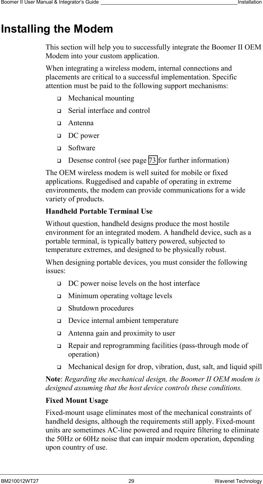
Installation_________________________________________________ Boomer II User Manual & Integrator’s Guide  Wavenet Technology  30  BM210012WT27 Other considerations include mobile usage, which typically implies vehicular applications. Some of the design implications of mobile usage include: Resets  The design must attempt to eliminate modem resets caused by supply voltage drops while the vehicle is starting. This is very disruptive to the network link. Supply Levels and Noise  Special care is required to ensure the modem is not subjected to DC voltages exceeding specifications. This could create costly damage to the RF section of the modem. Adhere to the power supply noise specifications in your design. Noise  Vehicular installations can be noisy. Antenna The antenna must be mounted like any other cellular or land mobile radio antenna. Usually the vehicle roof provides a good ground plane unless it is fabricated of non-metallic material such as fibreglass. Mounting the Boomer II OEM Modem to Your Device Before using your modem you must:   Mount the Boomer II OEM Modem to your device   Connect the Data Interface Port    Connect and position the antenna   Supply power A picture of the Boomer II OEM Modem is shown below.     LED Window Data Interface PortRF Connector
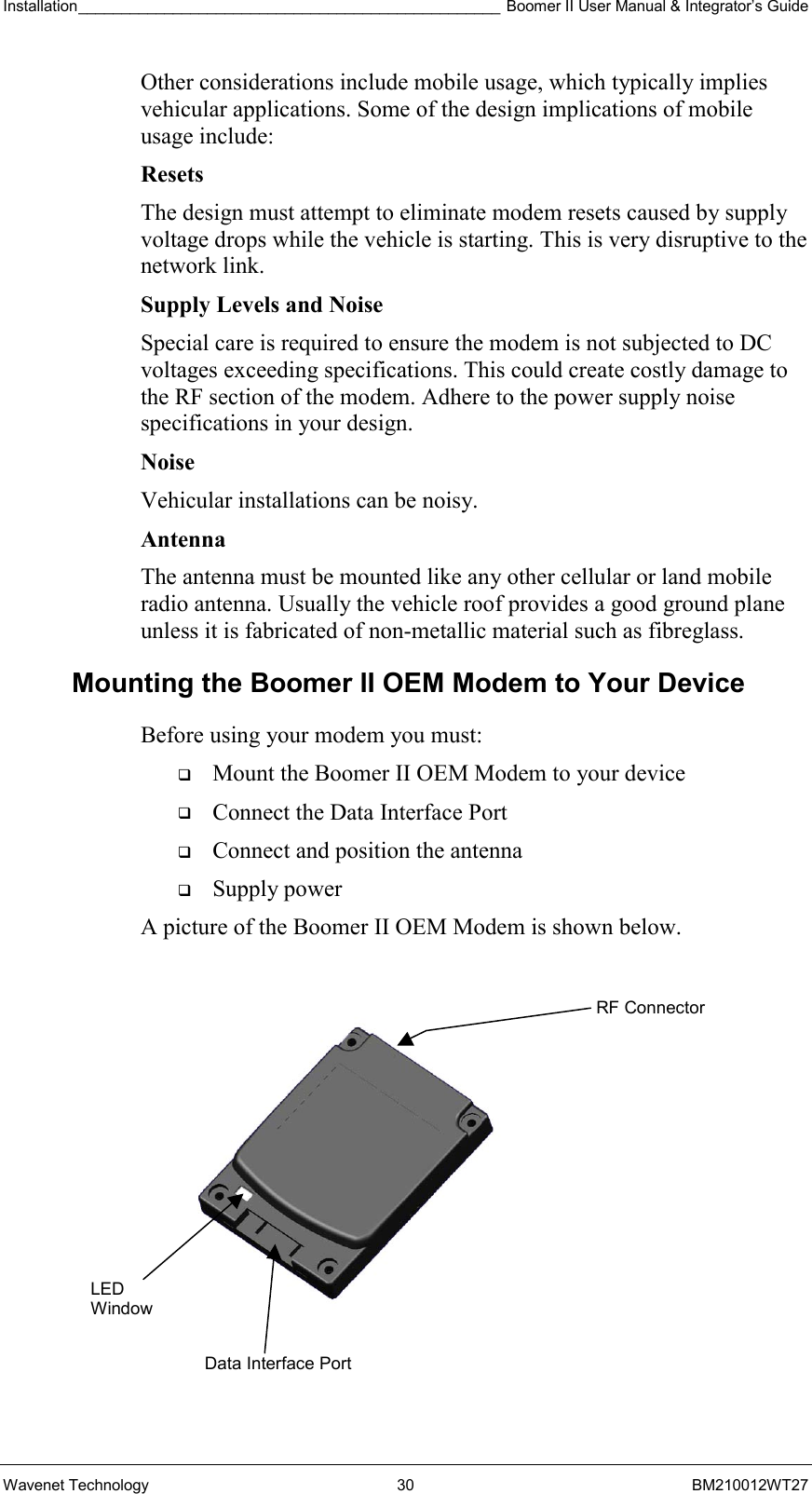
Boomer II User Manual & Integrator’s Guide _________________________________________________Installation  BM210012WT27 31 Wavenet Technology Proper mounting of the modem requires securely fastening it within the product housing. The mating surface should be flat and ensure a rigid mounting for the modem to minimise the transmission of vibration to the unit. There should be an adequate supply of airflow to ensure the modem’s temperature limits are not exceeded. To ensure ease of access for installation and troubleshooting, locate the modem within the product in such a way that serial I/O and antenna connections are readily accessible. Quick access to the modem allows it to be efficiently removed, probed, and functionally tested. The Boomer II OEM Modem has an M2 Mounting Bolt hole in each corner, which should be used to bolt the modem onto an appropriate surface. The hole pattern is four holes in a 60mm X 46mm X 42mm trapezoid, with each hole to suit an M2 (2.0mm) bolt. Refer to the following diagram.  Connecting the Data Interface Port There are two connectors to interface the Boomer II OEM Modem with your device.    RF Connector (described in the next section), and   Data Interface Port The data interface port is used to interface the modem to a serial computing device and a power supply. The power supply requirements are described in the next section. A flat 30-way Flexible Printed Circuit (FPC) cable (approx 0.3 mm thick with 0.5 mm centreline spacing) is used between the Boomer II OEM Modem’s data interface port and the host device or terminal. The connector specification is given below. Top View  Side View  Mounting Details Hole diameter: 4 x 2.30mm Fixing screw  size: M2 70 52  9  46.0 CTRS 42.0 CTRS
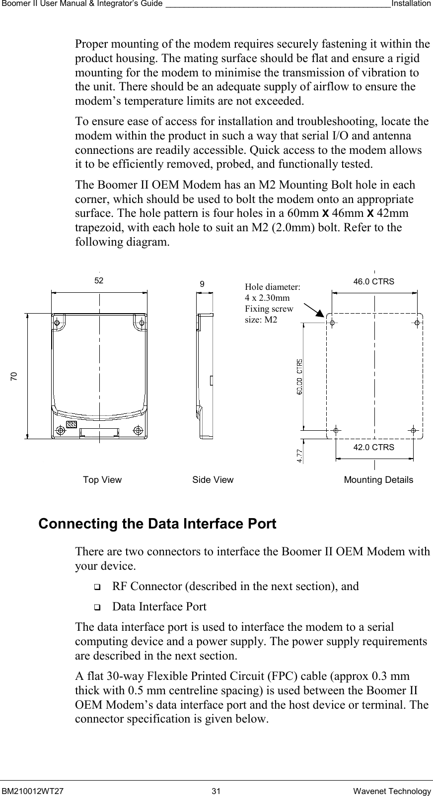
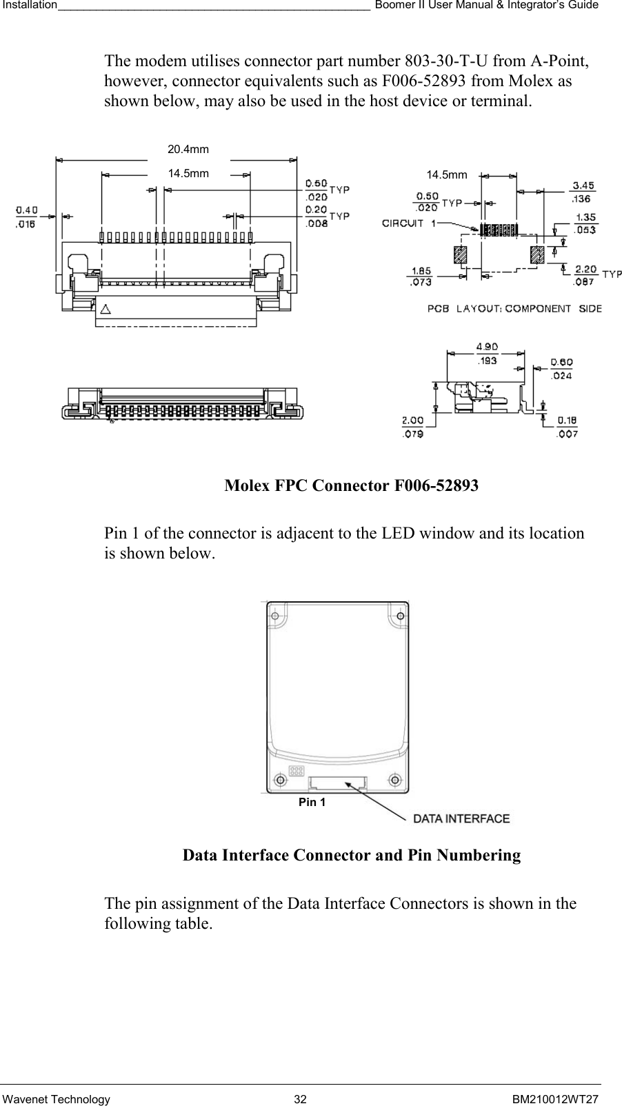
Installation_________________________________________________ Boomer II User Manual & Integrator’s Guide  Wavenet Technology  32  BM210012WT27 The modem utilises connector part number 803-30-T-U from A-Point, however, connector equivalents such as F006-52893 from Molex as shown below, may also be used in the host device or terminal.  Molex FPC Connector F006-52893  Pin 1 of the connector is adjacent to the LED window and its location is shown below.    Data Interface Connector and Pin Numbering  The pin assignment of the Data Interface Connectors is shown in the following table. Pin 1 20.4mm 14.5mm14.5mm
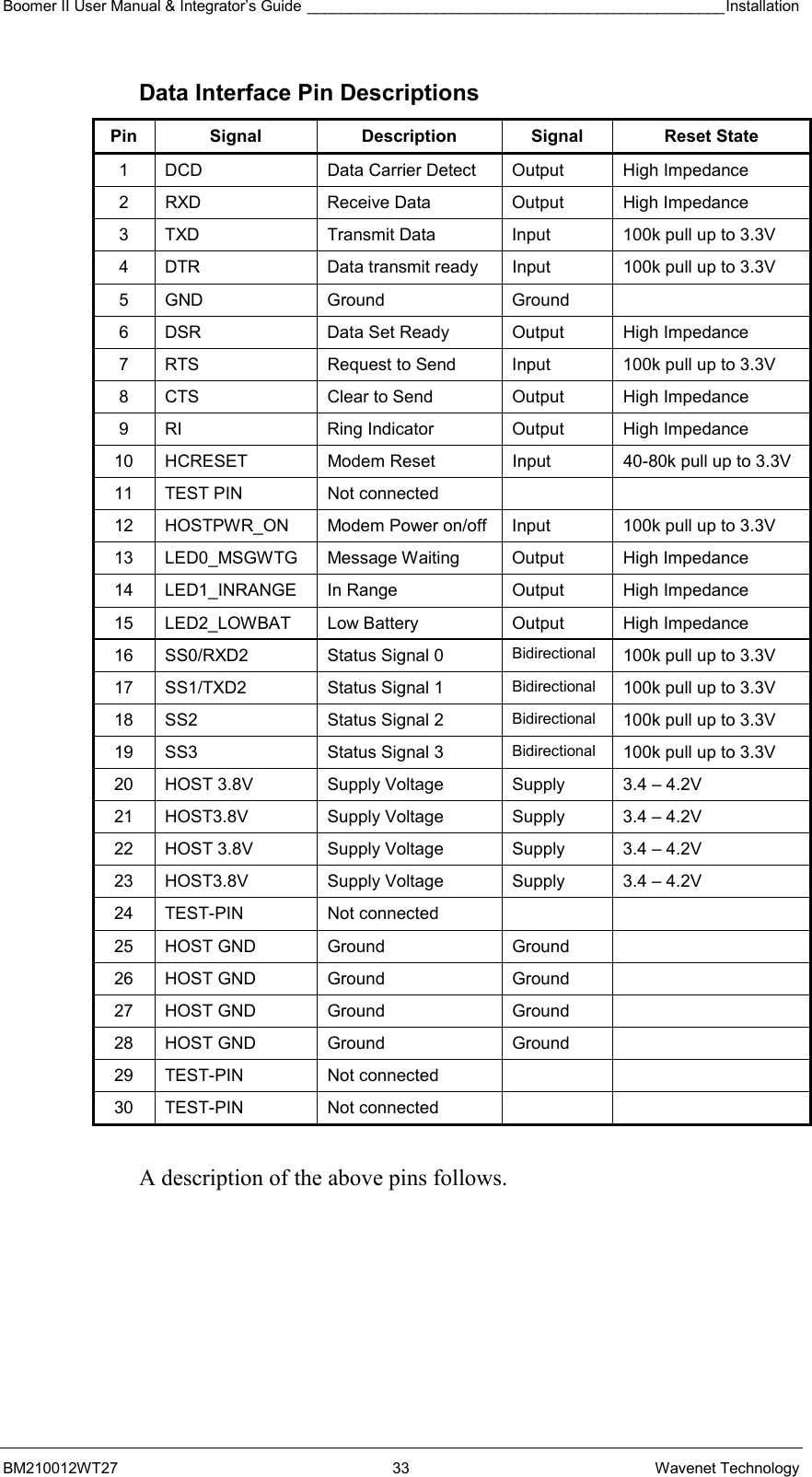
Boomer II User Manual & Integrator’s Guide _________________________________________________Installation  BM210012WT27 33 Wavenet Technology Data Interface Pin Descriptions Pin Signal  Description Signal  Reset State 1  DCD  Data Carrier Detect  Output  High Impedance 2  RXD  Receive Data  Output  High Impedance 3  TXD  Transmit Data  Input  100k pull up to 3.3V 4  DTR  Data transmit ready  Input  100k pull up to 3.3V 5 GND  Ground  Ground   6  DSR  Data Set Ready  Output  High Impedance 7  RTS  Request to Send  Input  100k pull up to 3.3V 8  CTS  Clear to Send  Output  High Impedance 9  RI  Ring Indicator  Output  High Impedance 10  HCRESET  Modem Reset  Input  40-80k pull up to 3.3V 11  TEST PIN  Not connected     12  HOSTPWR_ON  Modem Power on/off  Input  100k pull up to 3.3V 13 LED0_MSGWTG Message Waiting  Output  High Impedance 14  LED1_INRANGE  In Range  Output  High Impedance 15  LED2_LOWBAT  Low Battery  Output  High Impedance 16  SS0/RXD2  Status Signal 0  Bidirectional  100k pull up to 3.3V 17  SS1/TXD2  Status Signal 1  Bidirectional  100k pull up to 3.3V 18  SS2  Status Signal 2  Bidirectional  100k pull up to 3.3V 19  SS3  Status Signal 3  Bidirectional  100k pull up to 3.3V 20  HOST 3.8V  Supply Voltage  Supply  3.4 – 4.2V 21  HOST3.8V  Supply Voltage  Supply  3.4 – 4.2V 22  HOST 3.8V  Supply Voltage  Supply  3.4 – 4.2V 23  HOST3.8V  Supply Voltage  Supply  3.4 – 4.2V 24 TEST-PIN  Not connected     25 HOST GND  Ground  Ground   26 HOST GND  Ground  Ground   27 HOST GND  Ground  Ground   28 HOST GND  Ground  Ground   29 TEST-PIN  Not connected     30 TEST-PIN  Not connected      A description of the above pins follows.
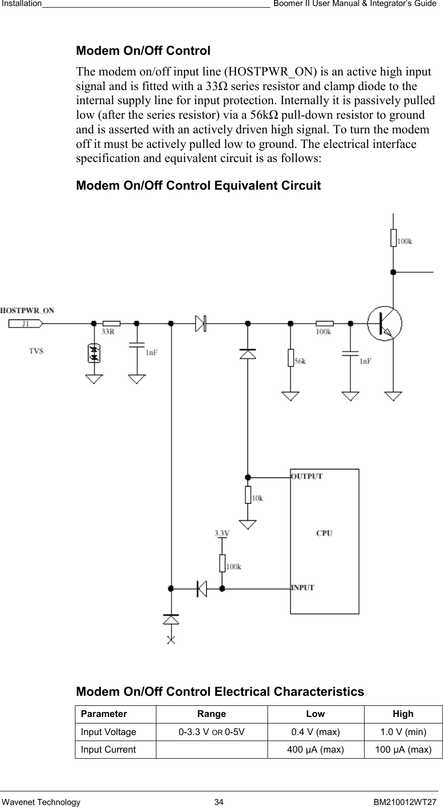
Installation_________________________________________________ Boomer II User Manual & Integrator’s Guide  Wavenet Technology  34  BM210012WT27 Modem On/Off Control The modem on/off input line (HOSTPWR_ON) is an active high input signal and is fitted with a 33Ω series resistor and clamp diode to the internal supply line for input protection. Internally it is passively pulled low (after the series resistor) via a 56kΩ pull-down resistor to ground and is asserted with an actively driven high signal. To turn the modem off it must be actively pulled low to ground. The electrical interface specification and equivalent circuit is as follows: Modem On/Off Control Equivalent Circuit  Modem On/Off Control Electrical Characteristics Parameter Range  Low High Input Voltage  0-3.3 V OR 0-5V  0.4 V (max)  1.0 V (min) Input Current    400 µA (max)  100 µA (max)
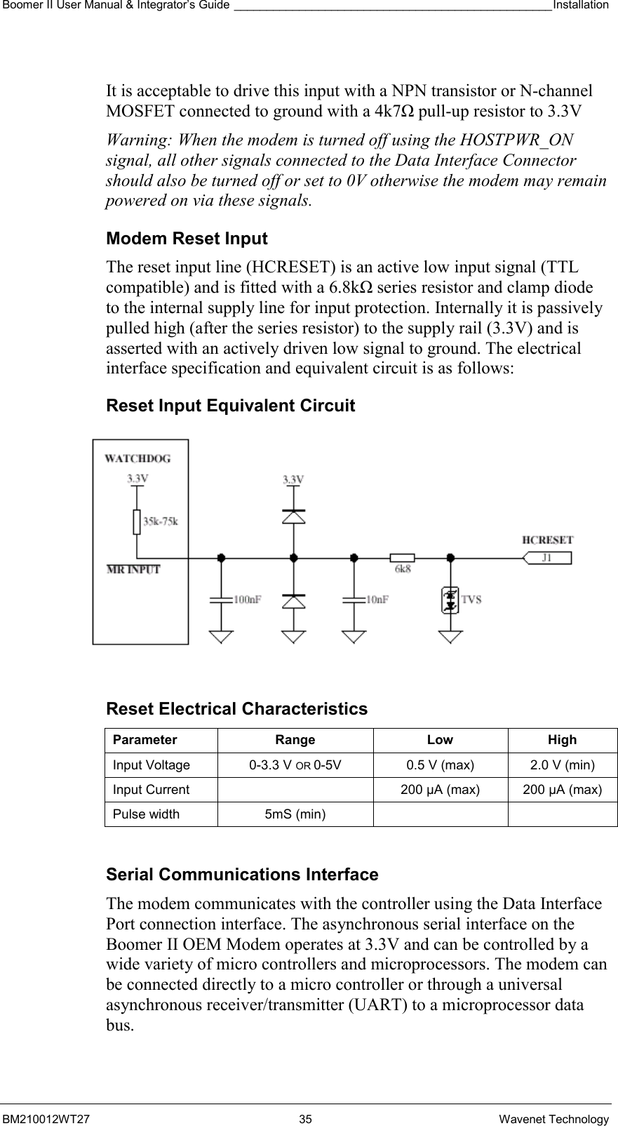
Boomer II User Manual & Integrator’s Guide _________________________________________________Installation  BM210012WT27 35 Wavenet Technology  It is acceptable to drive this input with a NPN transistor or N-channel MOSFET connected to ground with a 4k7Ω pull-up resistor to 3.3V Warning: When the modem is turned off using the HOSTPWR_ON signal, all other signals connected to the Data Interface Connector should also be turned off or set to 0V otherwise the modem may remain powered on via these signals. Modem Reset Input The reset input line (HCRESET) is an active low input signal (TTL compatible) and is fitted with a 6.8kΩ series resistor and clamp diode to the internal supply line for input protection. Internally it is passively pulled high (after the series resistor) to the supply rail (3.3V) and is asserted with an actively driven low signal to ground. The electrical interface specification and equivalent circuit is as follows: Reset Input Equivalent Circuit  Reset Electrical Characteristics Parameter Range  Low High Input Voltage  0-3.3 V OR 0-5V  0.5 V (max)  2.0 V (min) Input Current    200 µA (max)  200 µA (max) Pulse width  5mS (min)      Serial Communications Interface The modem communicates with the controller using the Data Interface Port connection interface. The asynchronous serial interface on the Boomer II OEM Modem operates at 3.3V and can be controlled by a wide variety of micro controllers and microprocessors. The modem can be connected directly to a micro controller or through a universal asynchronous receiver/transmitter (UART) to a microprocessor data bus.
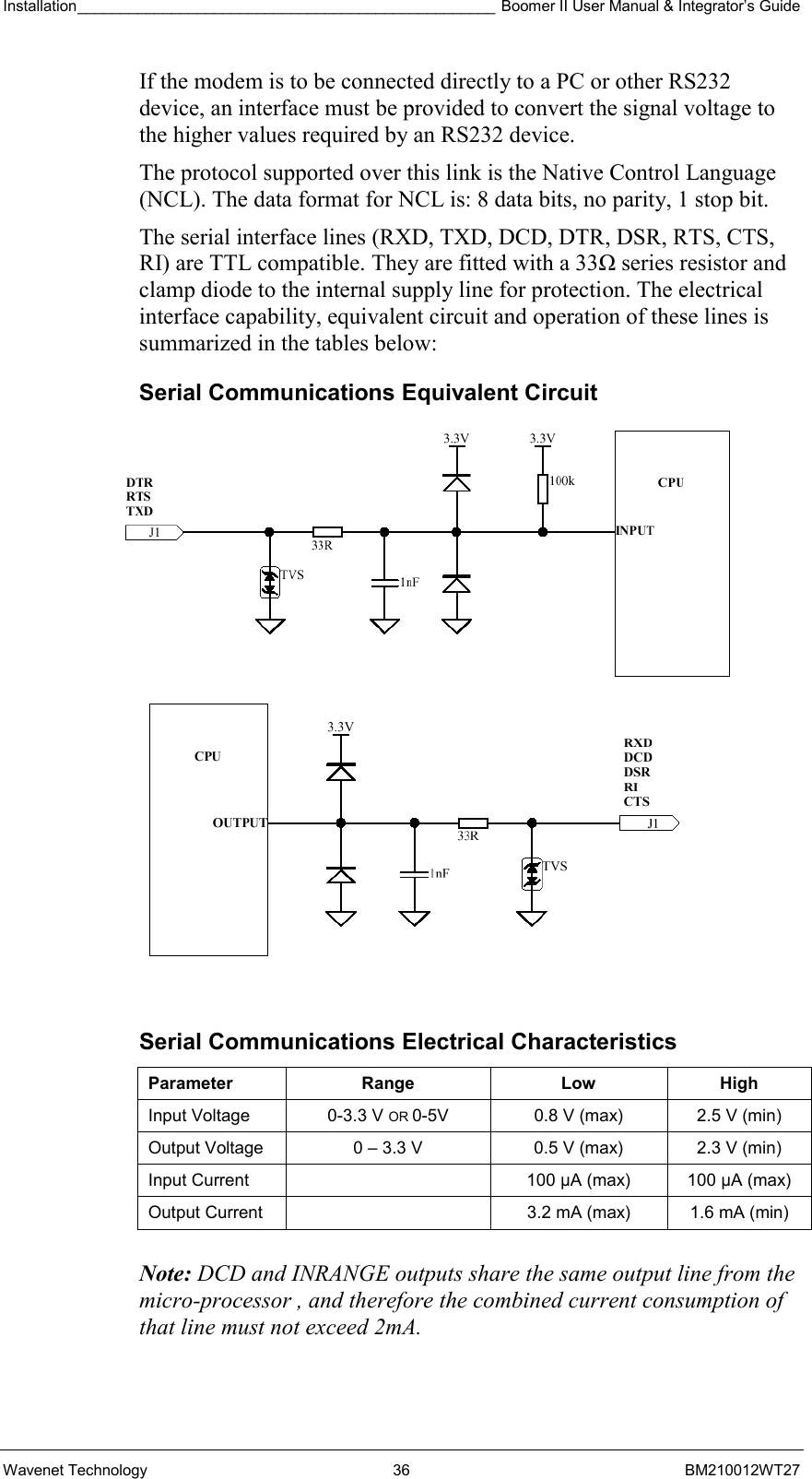
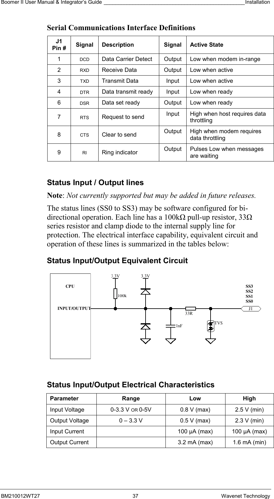
Installation_________________________________________________ Boomer II User Manual & Integrator’s Guide  Wavenet Technology  36  BM210012WT27 If the modem is to be connected directly to a PC or other RS232 device, an interface must be provided to convert the signal voltage to the higher values required by an RS232 device. The protocol supported over this link is the Native Control Language (NCL). The data format for NCL is: 8 data bits, no parity, 1 stop bit. The serial interface lines (RXD, TXD, DCD, DTR, DSR, RTS, CTS, RI) are TTL compatible. They are fitted with a 33Ω series resistor and clamp diode to the internal supply line for protection. The electrical interface capability, equivalent circuit and operation of these lines is summarized in the tables below: Serial Communications Equivalent Circuit   Serial Communications Electrical Characteristics Parameter Range  Low High Input Voltage  0-3.3 V OR 0-5V  0.8 V (max)  2.5 V (min) Output Voltage  0 – 3.3 V  0.5 V (max)  2.3 V (min) Input Current    100 µA (max)  100 µA (max) Output Current    3.2 mA (max)  1.6 mA (min)   Note: DCD and INRANGE outputs share the same output line from the micro-processor , and therefore the combined current consumption of that line must not exceed 2mA.
Boomer II User Manual & Integrator’s Guide _________________________________________________Installation  BM210012WT27 37 Wavenet Technology Serial Communications Interface Definitions J1 Pin #  Signal Description  Signal Active State 1  DCD  Data Carrier Detect  Output  Low when modem in-range 2  RXD  Receive Data  Output  Low when active 3  TXD  Transmit Data  Input  Low when active 4  DTR  Data transmit ready  Input  Low when ready 6  DSR  Data set ready  Output  Low when ready 7  RTS Request to send  Input  High when host requires data throttling 8  CTS  Clear to send  Output  High when modem requires data throttling 9  RI Ring indicator  Output  Pulses Low when messages are waiting  Status Input / Output lines Note: Not currently supported but may be added in future releases. The status lines (SS0 to SS3) may be software configured for bi-directional operation. Each line has a 100kΩ pull-up resistor, 33Ω series resistor and clamp diode to the internal supply line for protection. The electrical interface capability, equivalent circuit and operation of these lines is summarized in the tables below: Status Input/Output Equivalent Circuit  Status Input/Output Electrical Characteristics Parameter Range  Low High Input Voltage  0-3.3 V OR 0-5V  0.8 V (max)  2.5 V (min) Output Voltage  0 – 3.3 V  0.5 V (max)  2.3 V (min) Input Current    100 µA (max)  100 µA (max) Output Current    3.2 mA (max)  1.6 mA (min)
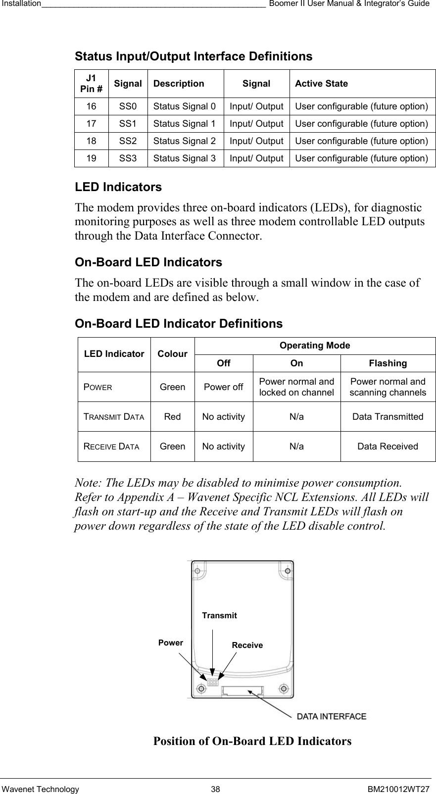
Installation_________________________________________________ Boomer II User Manual & Integrator’s Guide  Wavenet Technology  38  BM210012WT27 Status Input/Output Interface Definitions J1 Pin #  Signal Description  Signal  Active State 16  SS0  Status Signal 0  Input/ Output  User configurable (future option) 17  SS1  Status Signal 1  Input/ Output  User configurable (future option) 18  SS2  Status Signal 2  Input/ Output  User configurable (future option) 19  SS3  Status Signal 3  Input/ Output  User configurable (future option) LED Indicators The modem provides three on-board indicators (LEDs), for diagnostic monitoring purposes as well as three modem controllable LED outputs through the Data Interface Connector.  On-Board LED Indicators The on-board LEDs are visible through a small window in the case of the modem and are defined as below. On-Board LED Indicator Definitions Operating Mode LED Indicator  Colour Off On  Flashing POWER Green Power off Power normal and locked on channel Power normal and scanning channels TRANSMIT DATA  Red  No activity  N/a  Data Transmitted RECEIVE DATA  Green  No activity  N/a  Data Received  Note: The LEDs may be disabled to minimise power consumption. Refer to Appendix A – Wavenet Specific NCL Extensions. All LEDs will flash on start-up and the Receive and Transmit LEDs will flash on power down regardless of the state of the LED disable control.    Position of On-Board LED Indicators Power  Receive Transmit
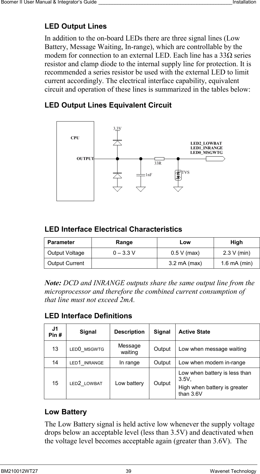
Boomer II User Manual & Integrator’s Guide _________________________________________________Installation  BM210012WT27 39 Wavenet Technology LED Output Lines In addition to the on-board LEDs there are three signal lines (Low Battery, Message Waiting, In-range), which are controllable by the modem for connection to an external LED. Each line has a 33Ω series resistor and clamp diode to the internal supply line for protection. It is recommended a series resistor be used with the external LED to limit current accordingly. The electrical interface capability, equivalent circuit and operation of these lines is summarized in the tables below: LED Output Lines Equivalent Circuit  LED Interface Electrical Characteristics Parameter Range  Low High Output Voltage  0 – 3.3 V  0.5 V (max)  2.3 V (min) Output Current    3.2 mA (max)  1.6 mA (min)   Note: DCD and INRANGE outputs share the same output line from the microprocessor and therefore the combined current consumption of that line must not exceed 2mA. LED Interface Definitions J1 Pin #  Signal Description Signal Active State 13  LED0_MSGWTG Message waiting  Output  Low when message waiting 14  LED1_INRANGE  In range  Output  Low when modem in-range 15  LED2_LOWBAT Low battery Output Low when battery is less than 3.5V,  High when battery is greater than 3.6V  Low Battery The Low Battery signal is held active low whenever the supply voltage drops below an acceptable level (less than 3.5V) and deactivated when the voltage level becomes acceptable again (greater than 3.6V).  The
Installation_________________________________________________ Boomer II User Manual & Integrator’s Guide  Wavenet Technology  40  BM210012WT27 transitions will occur at the same time as the low battery event occurs (or would occur if the event was activated).  Note that in the case of a very fast transition between voltages, it may take up to 20 seconds for the modem to confirm a change in battery status. Message Waiting The Message waiting signal is held active low whenever there is at least one complete message waiting in the outbound buffers (including the reread buffer). In-Range The In Range signal is held active low whenever the modem is in range. It tracks the function of the Data Carrier Detect (DCD) signal.  Selecting & Positioning the Antenna  Use this information to assist you in selecting the appropriate antenna to incorporate into your product package. For specific detailed information, Wavenet recommends that you use the expertise of an antenna design engineer to solve individual application concerns. Antenna Safety The design of the integrated product must be such that the location used and other particulars of the antenna comply with the appropriate standards of the country in which the host device or terminal is to be used. The integrator should refer to the statement of Compliance on page 12 of this manual and Regulatory Requirements section on pages 23-27 for country requirements. Mobile and Portable Devices In the environment where portable devices are in use, many variables exist that can affect the transmission path. In this case, it would be preferable to use a vertically polarized, omni directional antenna. Antennas for portable devices include the following designs: Internal antenna (invisible or pull-up)  An internal antenna must provide a gain sufficient to meet network specifications. Cable routing from the modem to the antenna needs to avoid RF sensitive circuits and high level, high-speed clock circuits. Consider:   The location of the antenna to avoid RFI to a computing device.   Good shielding to the display and other RF-sensitive components   The most efficient method of cable routing Otherwise, antenna gain can be offset by cable loss. A typical coaxial cable is very thin, such as RG178B used in portable devices, and cable loss can be 1dB or more per metre. Some coaxial cable manufacturers
Boomer II User Manual & Integrator’s Guide _________________________________________________Installation  BM210012WT27 41 Wavenet Technology market relatively thin double braid coaxial cables. These cables show much better isolation than single braid cables, typically by 30 to 40dB. These double braid cables reduce radiation and RF pick-up when routed inside a portable device. External antenna, removable and directly connected to the device  You can design a portable device that can use an off-the-shelf, plug-in antenna, such as a ¼ wave monopole or ½ wave dipole antenna. Typical gain of these omni directional antennas is 0dBi and 2.14dBi, respectively. Cabling demands the same consideration as an internal antenna application. In a typical laptop application, the antenna must be placed as far as possible from a display to avoid deflection. This usually causes a deep null in radiation patterns. External, remote antenna  For remote antenna application use the same design approach as internal designs, including the RF cable routing of the external connector. You can choose an off-the-shelf mobile antenna of omni directional ½ wave length.  A double braid coaxial cable such as RG223 from the device to the antenna is recommended if the cable length is more than a metre. The difference in cable loss between low cost RG58 and the more expensive RG223 is approximately 4.5dB per 30 metres. If the cable must be routed through noisy EMI/RFI environments, a double braid cable such as RG223 can reduce radiation and pick-up by 30 to 40dB. Fixed Devices Fixed data device applications use the same design recommendations as a portable device with a remote antenna. As for the RF connector of an external antenna, whether it is a plug-in type or a remote type, the most economical and practical choice is a TNC threaded connector. TNC has a good frequency response to 7GHz, and leakage is low. A mini UHF threaded connector provides adequate performance and is an economical choice. If the size of the TNC and mini UHF connectors becomes critical, consider an SMA threaded connector or an SMB snap fit connector. (The SMB connector does not accept an RG58 or RG223 cable).
Installation_________________________________________________ Boomer II User Manual & Integrator’s Guide  Wavenet Technology  42  BM210012WT27 Selecting an Antenna The requirements for the antenna used with the Boomer II OEM Modem are: Antenna Gain:  1 dBi (isotropic) maximum average gain if module FCC approvals are to be used without separate equipment approval for the host product. Impedance: 50Ω  Centre Frequency:  833MHz ± 5MHz  (for 800MHz modem)   921MHz ± 3MHz  (for 900MHz modem)  Frequencies of operation:  806 to 825MHz (for 800MHz transmit)    851 to 870MHz (for 800MHz receive)   896 to 902MHz (for 900MHz transmit)    935 to 941MHz (for 900MHz receive)  Acceptable return loss:  VSWR < 1.5 or RL < -14dB (recommended)    VSWR < 2.0 or RL < -10dB (minimum)  The power output of the Boomer II OEM Modem is nominally 1.8W at the antenna port. The antenna gain or loss will affect this value.  Connecting the Antenna The Boomer II OEM Modem Module provides an MMCX RF connector located at the top of the unit, to attach to the antenna cable.  The antenna does not plug directly into the modem but uses an antenna cable to interface between the device and the modem. The antenna cable should be a low loss, 50Ω impedance and have a MMCX plug that can mate with the modem’s MMCX socket (82MMCX-S50-0-2). It is recommended that a Huber+Suhner connector be used to connect to the modem as below:   11 MMCX  Straight Connector   16 MMCX  Right Angle Connector If an extension cable is required to the antenna, it should be low loss, as short as possible and an impedance of 50 ohms. Proper matching connectors should be used, as each connector introduces a return loss and reduces performance.
Boomer II User Manual & Integrator’s Guide _________________________________________________Installation  BM210012WT27 43 Wavenet Technology Positioning the Antenna Positioning the antenna will affect the gain provided by the antenna. The antenna should be orientated so that it provides vertical polarisation as the DataTAC network is based on vertically polarised radio-frequency transmission. The antenna should be located as far from the active electronics of the computing device as possible. Typically, a metal case of a computing device and its internal components may attenuate the signal in certain directions. This is undesirable as the sensitivity and transmit performance of the Boomer II would be reduced. However, careful use of metal used for the ground plane for an antenna can improve the antenna gain and the coverage area for the system. If your device is designed to sit on a surface, the antenna should be positioned as far from the bottom of the device as possible. This is to reduce the radio frequency reflections if the device is placed on a metal surface. If your device is hand held or is worn next to the body, the antenna should be positioned to radiate away from the body. The integrator should refer to the statement of Compliance on page 12 of this manual and Regulatory Requirements section on pages 23-27 for country requirements.  Source Based Time Averaging Function For portable or handheld applications the integrated terminal or host must comply with OET Bulletin 65 and Supplement C (June 2002) with respect to Specific Absorption Rate (SAR) requirements.  The Boomer-II modem module operates on a packet data network which sets the timing of most aspects of the RF signalling protocol. The shortest transmit event over which the Boomer-II modem has control is a transmit transaction which is comprised of a series of transmit pulses. For portable or handheld applications a source based time averaging function has been incorporated in the Boomer-II modem firmware. This function limits the transmit duty cycle by controlling the timing of when transmit transactions are initiated and the delay period between them. When a data transmission occurs, the actual transmit time is recorded. Subsequent data transmissions are inhibited until a delay period (idle time) has elapsed to ensure the average duty cycle of transmissions is less than the preset “Duty Cycle” limit. Any delayed user data that is to be transmitted will be buffered until it is permitted to be sent.
Installation_________________________________________________ Boomer II User Manual & Integrator’s Guide  Wavenet Technology  44  BM210012WT27 The algorithm for the Source Based Time Averaging transmit control and the relevant parameters are given below:   Idle_Time = Duty_Factor * Transmit_Duration   Duty Factor = (100 – Duty_Cycle%) / Duty_Cycle%   Duty_Cycle% = Preset limit for SAR compliance  Source Based Time Averaging Transmit Algorithm  The Boomer-II modem module has an overall transmit Duty Cycle limitation of 30% (maximum) to physically protect the modem hardware.  The default Duty Cycle preset in the factory at the time of manufacture is 10%.  Other duty factors and SAR evaluation must be addressed at the time of OEM integration into any final host product and is the responsibility of the OEM Integrator. The algorithm and preset Duty Cycle is recorded in the module firmware at the time of manufacture and cannot be altered by the end user.  No Yes No  Wait for data   Decrement Idle_Time  Transmit data    Determine actual Transmit_DurationBuffer data  Decrement Idle_Time Yes  Has the transmit Idle_Time expired?  Set Idle_Time = Duty_Factor * Transmit_Duration  Any data to transmit?
Boomer II User Manual & Integrator’s Guide _________________________________________________Installation  BM210012WT27 45 Wavenet Technology Supplying Power The Boomer II OEM Modem must be provided with a clean power source capable of delivering bursts of high current. The modem draws its power in bursts. The power required changes rapidly depending on whether the modem is transmitting, receiving or on standby. Ratings The power supply requirements are: Voltage:  3.8V (3.4 to 4.2V range) Transmit Current:  1.6A maximum   (2.2A maximum if antenna mismatched) Transmit Duration:  32ms (minimum)    7s (maximum) Duty Cycle  30% (maximum) data dependant Receive Current  85 mA (maximum) Standby Current  4.6 mA (maximum)    Add ~1.2mA if LED’s enabled Off current consumption:  100 µA (nominal) Power Supply Ripple:  < 15mV peak to peak Management The power supply is one of the key issues of design of wireless terminals. Due to the burst nature of transmit periods the power supply must be able to deliver high current peaks for short periods of 32ms to a maximum of 7 seconds (RD-LAP 9600 bps) or for 20 seconds (MDC 4800 bps). During this time the drop in the supply at the module itself must not exceed 200mV (total at the module), such that at no time module shall module supply drop below 3.4V and ripple must not exceed 15mVp-p during transmit. The maximum transmit current into a matched antenna is 1.6A, however, this can increase if antenna mismatch occurs. Wavenet recommends designing a robust power supply that can provide adequate power under non-ideal conditions such as an improperly matched antenna, where current can be up to 2.2A. It is recommended that for ensuring power supply margin the following be done:   A short FPC cable (e.g < 100mm) is used to minimise power supply voltage drop during transmission.
Installation_________________________________________________ Boomer II User Manual & Integrator’s Guide  Wavenet Technology  46  BM210012WT27   The power supply should be set above nominal 3.8V to accommodate worst case power supply drop. i.e. 4.0V.   The power supply should have good regulation with < 200mV drop at 2.2A.   Adequate supply decoupling (10,000uF min.) is added at terminal connector to reduce ripple and smooth supply voltage steps.   The power supply be capable of supplying non-ideal current consumption conditions of up to 2.2A for up to 20 seconds and with a duty cycle (set by data usage) ~ 30% maximum.   Multiple pins are assigned to both power and ground connections for the modem. Connection of all designated pins to the appropriate supply or ground in the host is necessary to accommodate modem current requirements.   The host device or terminal must provide a continuous supply.  The modem is fully compliant with the DataTAC Power Save Management system. The modem exists in the lowest power state possible while still providing uninterrupted service. By de-asserting the HOSTPWR_ON signal, the modem disconnects from the network then enters a near-zero power state. The modem resets if the power source is cycled. This can cause network service issues, since the modem might not have had a chance to de-register. The modem spends the majority of time in sleep mode. Conservation In installations requiring power conservation (such as, when the modem is powered from a battery or solar cell), you must monitor modem power consumption in various operating states. Even though the Boomer II OEM modems are designed for minimal power consumption, by using the network Power Save protocol offered by DataTAC networks you can further reduce power consumption. Another power saving idea is to activate the modem only when it is needed. Note: The on-board LEDs may be disabled to minimise power consumption. Refer to Appendix A – Wavenet Specific NCL Extensions. All LEDs will flash on start-up and the Receive and Transmit LEDs will flash on power down regardless of the state of the LED disable control. Power Save Protocol The modem typically uses current provided by the host battery. For the product to be usable for a reasonable period in portable applications, the host battery power must be conserved. To meet this requirement, the modem uses DataTAC Power Save protocol. The Power Save Protocol defines the following four modem power consumption states:
Boomer II User Manual & Integrator’s Guide _________________________________________________Installation  BM210012WT27 47 Wavenet Technology Off  The modem is turned off or the host (battery) has failed. Sleep  The processor is sleeping and wakes up to an interrupt, but the RF section is off. Receive  The processor is actively processing information; the RF sections are on and demodulating data. Transmit  The processor is actively processing information; the RF sections are on and transmitting data. Power Profile The modem’s power consumption profile depends on the usage and the network configuration of the Power Save protocol. For example, the following numbers present a typical profile for the Boomer II modem based on reasonably heavy usage and assuming a 3.8V supply current: (Power Save Mode = Maximum)   80 % Sleep @ 4.4 mA typical   19.9 % Receive @ 76 mA typical   0.1% Transmit @ 1.6A typical The actual percentage of total time spent in each state (transmit, receive, sleep) is a function of the following variables. Network configuration  On networks supporting Power Save operation, the network configuration impacts how long the modem must be in the sleep state. Note: Neither Wavenet nor any developer has any direct control over the network configuration. Networks supporting Power Save are typically configured to preserve the battery life of modems of their subscriber base. Message traffic model  The message traffic model defines how many messages are transmitted and received, and the average length of the messages sent and received in a given working day. For instance, a dispatch application could have a message traffic model as follows:   Messages transmitted in 8 hour day: 25   Average length of transmission: 120 bytes   Messages received in 8 hour day: 10   Average length of received message: 30 bytes This analysis of message traffic allows the power consumption profile to be assessed in terms of percentage of time spent transmitting, receiving, and sleeping. (For more information, see Develop a Message Model on page 16.) Usage of group LLIs  Some applications require the use of group LLIs, such as a stock quotation broadcast service. Each active group LLI (in addition to the
Installation_________________________________________________ Boomer II User Manual & Integrator’s Guide  Wavenet Technology  48  BM210012WT27 modem's factory loaded individual LLI) increases the percentage of time the modem stays in the receive state, thereby increasing its overall current consumption. Roaming Time The amount of time the modem spends scanning a channel or roaming to a new channel will affect the current consumption. The current consumption is dependant on the Network type  (Private or Public) and the System type (MFR or SFR). Power Control The terminal host provides the supply rail (HOST 3.8V) to the modem through the Data Interface Connector.  The terminal host turns the modem ON by asserting the HOSTPWR_ON signal. The terminal host may request the modem to turn OFF by de-asserting the HOSTPWR _ON or by sending a specific NCL command across the serial interface. For the modem to turn OFF after an NCL request the HOSTPWR_ON signal must be de-asserted. ESD protection is provided on all power supply lines and on each I/O line. Power-Up Sequence Reference should be made to the Power-UP Timing Diagram below when reading the following Power-UP Sequence description. To turn the modem ON, power must be applied (HOST 3.8V) and the terminal host asserts the HOSTPWR_ON signal.   The modem contains an internal voltage detector and reset delay circuit to generate a reset signal for the CPU to ensure orderly and reliable software initialisation. An externally controllable reset signal (HCRESET) is optionally available if the terminal host wants reset synchronisation or to force a modem reset while power is still applied.  If the HCRESET signal is used, once it is de-asserted the modem CPU will be able to initialise.  Once out of reset the first operation is the boot-up of the modem CPU. At this time CTS is momentarily asserted, then de-asserted. After a successful boot up, the CPU starts the modem initialisation sequence. After the initialisation sequence, the Native Mode interface and the serial interface are active.  Following successful initialisation, the modem asserts DSR and performs the initialisation protocols for both the NCL DTE interface and the RF network. After successfully initialising the NCL DTE interface, the modem asserts CTS. After the network ACK of the registration sequence, DCD is asserted.
Boomer II User Manual & Integrator’s Guide _________________________________________________Installation  BM210012WT27 49 Wavenet Technology Power-Up Timing Diagram                         Note: HCRESET, CTS, DSR, DCD, the LEDs and the internal modem reset are all active low signals.  Power Up Diagram Callouts 1  Power is supplied to the modem 2  The HOSTPWR_ON signal is asserted to turn on the modem. 3  The HCRESET signal is de-asserted. 4  The internal modem reset is released to allow the modem boot up sequence. 5  The modem exits the boot load state, is operational and is ready to communicate with the DTE.  Modem Internal Power Modem Internal Reset CTS DSR DCD LED’s ~ 300 ms Initialisation 4 5 Boot Stage Modem is now software controlled Modem is now  Operational Network Connect IN RANGE Optional Delay 1 HOST 3.8V HOSTPWR_ON  2 HCRESET (Optional) 140 ~ 280 ms Reset Delay 3 Optional Delay
Installation_________________________________________________ Boomer II User Manual & Integrator’s Guide  Wavenet Technology  50  BM210012WT27  Power Down Sequence The terminal host may request the modem to turn OFF by de-asserting the HOSTPWR _ON or by sending a specific NCL command across the serial interface. For the modem to turn OFF after an NCL request the HOSTPWR_ON signal must be de-asserted.  Warning: The power supply rail must be maintained during a power down sequence or else memory may be corrupted. The soft shutdown process starts when the HOSTPWR_ON control line is de-asserted. The shutdown process consists of the modem first de-registering from the network and de-asserting the DCD line. Next, it saves the modem configuration and network channel information. The modem then de-asserts the DSR line, signalling the modem is no longer in a ready state. This process can take a few seconds to complete. At this point, the host can remove the power from the modem and still maintain most of the modem settings and last registered network channel. The modem can be left with power applied and HOSTPWR_ON de-asserted. The reset line HCRESET can be asserted at this time in preparation for the next power-up sequence. This is optional and is intended for rebooting the modem only. Resetting the modem causes a cold start and flushes the saved modem settings. The following diagram shows the sequence for these actions. Power-Down Timing Diagram               Note: DSR and DCD are active low signals. HOSTPWR_ON DCD DSR Modem internal power control Modem Internal Power 1234Modem software is OperationalNetwork Deregistration  RF Protocol Requirement
Boomer II User Manual & Integrator’s Guide _________________________________________________Installation  BM210012WT27 51 Wavenet Technology  Power Down Diagram Callouts 1  HOSTPWR_ON is de-asserted from the host device to the modem.  Important: The power rail must be present for up to ten seconds (typically two seconds) after HOSTPWR_ON is de-asserted for the deregistration process to complete orderly. 2  The modem starts the soft shutdown process. The battery status indicator pulses quickly until the shutdown steps are complete.  The modem initiates the deregistration process from the network and upon completion de-asserts DSR and DCD. DCD signifies network detachment, and DSR shows the modem’s readiness state. 3  After deregistration, the internal modem CPU power-on signal is de-asserted. This deactivates the internal modem power rail to the radio. 4  At this point you can optionally de-asset HOSTPWR_ON signal to the modem and assert the HCRESET line to the modem. Batteries The Boomer II OEM Modem may be powered by batteries if used with a handheld device. For battery operated devices, battery selection is a critical decision, requiring consideration of many factors. These include cell size, internal impedance, charging requirements, and susceptibility to common battery phenomena, such as memory effect or overcharging. Each of these factors is discussed in detail in this section. The selected battery must be able to meet the Boomer II power requirements as mentioned previously. Three prevailing battery technologies exist today:   Nickel cadmium (NiCad) batteries may be used for devices requiring wide temperature ranges.    Nickel metal hydride (NiMH) and    Lithium ion (Li+) batteries may also be used for devices utilised above 0ºC. Specifications for these batteries should be obtained from the manufacturer. NiCad   Most mature technology   Lower energy density (energy/volume) than NiMH or Li-ion   Available in all cell sizes, including AA, 2/3A, 4/5A, A, 4/3A, and so on. This represents the greatest number of packaging options.   Exhibits a memory effect when not occasionally discharged below the lower extent of its operating voltage. The memory effect reduces the usable capacity of each battery cell.
Installation_________________________________________________ Boomer II User Manual & Integrator’s Guide  Wavenet Technology  52  BM210012WT27   Internal impedance of 25-30µΩ per 1.2V cell   Typical cell voltages are 1.2V, with multiple cells used to obtain higher operating voltages   Can withstand high current pulses, which are characteristic of packet data applications   Typical charge method is −∆ V (known as negative delta voltage), which involves charging the battery while looking for the battery voltage to peak. Then enter a slight overcharge condition, where the voltage actually begins to decrease prior to terminating battery charging. NiCad is the most robust battery technology available today for non vehicular applications. NiCad can withstand over charging, over discharging, and harsh environments with reasonable resilience.   Raw battery cells or battery packs can be purchased from suppliers NiMH   Mature technology with potential for improvements in battery chemistry and energy density over the next five years   Higher energy density than NiCad, but lower than Li-ion   Available in standard sizes AA, 2/3A, 4/5A, A and 4/3A and some prismatic (rectangular) configurations   Exhibits the memory effect in a manner similar to NiCad technology, but at a less pronounced level   Internal impedance of 35-49µΩ per 1.2V cell   Typical cell voltages are 1.2V, with multiple cells used to obtain higher operating voltages   Earlier NiMH battery chemistry could be damaged by high current discharge pulses. Newer battery chemistry has eliminated this problem. When purchasing batteries of this type, determine if high current pulse discharging is an issue.   Typical charge method is dT/dt, where T is temperature. As the battery reaches full charge, any further energy is dissipated as heat. A temperature threshold is used to terminate the charge cycle in conjunction with voltage monitoring. NiMH is more sensitive to overcharging then NiCad and exhibits decreased capacity if repetitively overcharged.   Raw battery cells or battery packs can be purchased from suppliers. Li-ion   Reasonably mature technology leaving lots of potential for increased capacity   Higher energy density than either NiCad or NiMH
Boomer II User Manual & Integrator’s Guide _________________________________________________Installation  BM210012WT27 53 Wavenet Technology   Availability is an issue, as most suppliers do not sell cells, but force customers into particular solutions through their battery pack designs. Purchasing cells in an effort to design your own battery pack may be problematic due to cell lead times.   Li-ion does not exhibit the memory effect and is unaffected by partial discharging-charging cycles   Internal impedance of 100-150mµΩ per 3.6V cell. Li-ion batteries are very susceptible to damage due to over discharge and high current pulses. As a result, manufacturers recommend that a protection circuit be added to battery pack designs. The resultant internal impedance of a battery pack with protection circuitry can reach the 500mΩ level.   Typical cell voltages are 3.6V with multiple cells used to obtain higher operating voltages.   Li-ion batteries are very sensitive to over-discharge and represent a hazard if not properly designed with protection circuitry.   Typical charge method is constant-voltage, constant-current. Applying Battery Technologies When reviewing different battery technologies, consider the following characteristics of OEM devices incorporating wireless data modems. Current drain is not constant  Typically, battery manufacturers specify the battery discharge profiles by assuming a constant-current drain model. In a wireless data system, the constant current drain model no longer applies. There are three levels of current drain contributions that can be expected: sleep, receive, and transmit. The modem cycles through these different states throughout the time it is powered on and in contact with the wireless network. To determine the realistic battery life or capacity for your product, you must contact the battery manufacturer or experiment by transmitting for various durations. Peak currents during transmissions Since transmissions are typically short, the resultant current drain during transmissions can be viewed as current pulses. These pulses must be considered when selecting the proper battery technology, since not all technologies are equally tolerant of current pulses. Additionally, the internal impedance of the battery must be taken into account at the peak currents during transmissions, since this is the time when the largest voltage drop occurs across the battery terminals. Adequate supply guard-band must be designed in to ensure that the modem and any other circuitry in the final product are not reset during transmissions.
Installation_________________________________________________ Boomer II User Manual & Integrator’s Guide  Wavenet Technology  54  BM210012WT27 Messaging model To determine the required battery capacity for your product, you need to define the messaging model for your target market. In regard to battery selection, the messaging model details the following information:   Optimal number of hours per day of use prior to recharging the battery   Number of messages transmitted per hour   Number of messages received per hour   Average length of transmitted messages Using this information and the typical current drains of the modem and other circuitry present in your product, you can define the requirements for battery supply voltage and capacity.  Battery Recharging Plug-in Supplies A mains plug-in supply must be designed to ensure that voltage spikes, lightening and other power fluctuations cannot damage the Boomer II. Transient voltage protection zener diodes or other spike arrestor circuits may be added to keep the inputs within the power requirements mentioned previously. These should have a value of 20V and be placed on the supply side of the regulator circuit. Automotive Supplies Extra protection is required from an automotive supply to protect the Boomer II OEM Modem from power fluctuations when used in an automobile. The electrical transient conditions (e.g. battery jump start), may damage the modem if not adequately clamped and filtered.  Environmental Considerations The environmental requirements of the Boomer II OEM Modem are as follows:   You should ensure these limits are not exceeded in the intended application.Operating Temperature:  -30° to +60°C  Storage Temperature:  -40° to +70°C  Relative Humidity  0 to 95% non-condensing
Boomer II User Manual & Integrator’s Guide ___________________________________________________ Testing BM210012WT27 55 Wavenet Technology Using the Modem Test Jig The Boomer II Test Jig provides RS-232 serial interface ports between a PC and the modem. It is designed to enable you to quickly interface the Boomer II to a standard PC (through a COM port) or a terminal device with an RS-232 serial port.  The test jig acts as a temporary host for the modem and provides access points to the radio’s communication port, allowing you to monitor activity with a logic probe, multimeter or oscilloscope. Features   All Input/Output Lines configurable by jumpers and/or accessible through parallel FPC connector.   On-board dual RS232 Serial Communication interface ports with DB9 connectors   Through the SPY MODEM connector, you can monitor the data transmitted from the modem (RX, DSR, and CTS).   Through the PORT 2/SPY PC connector, you can monitor the data transmitted from the PC (TX, RTS and DTR), or talk to the second serial port of the modem. You can make this choice by putting all five jumper links on the right or left side of the RDW header connector near the port.   Switches and LED indicators on SS0 - SS3 modem I/O lines.   On-board voltage regulator for Boomer II OEM supply rail.   On-board LEDs for three external signals: Low battery Message waiting In range   On-board antenna matching network allowing conversion from MMCX to SMA connectors. Updates From time to time updates may be provided for the Boomer-II test jig and these should be implemented as per the Update Notice. If you are unsure if your test jig does not incorporate all the latest updates please contact Wavenet Technology.
Testing ___________________________________________________ Boomer II User Manual & Integrator’s Guide Wavenet Technology  56  BM210012WT27 Exploring the Boomer II Test Jig The test jig comprises the following components:                     On / Off switch  Switches the power to the test jig on or off. DC Jack  Provides power to the test jig. (3.8V) DIP Switch  8-way DIP switch used to configure the test jig. The following table shows the DIP switch configuration.  Dip Switch # Signal On  Off  Default Position 1  PA7  Always leave this switch in the OFF position  OFF 2  OSC OFF  Always leave this switch in the ON position  ON 3  SS3  3V  10k Pull down to GND  OFF 4  SS2  3V  10k Pull down to GND  OFF 5  SS1  3V  10k Pull down to GND  OFF 6  SS0  3V  10k Pull down to GND  OFF 7  H-P-ON  Turn the modem off  Turn the modem on  OFF 8  RESET  Keep modem reset  Keep modem in working status  OFF On/Off Switch DC Jack Input Supply  Port 2 / SPY PC Interface DB9 Connector 8-way DIP switch On-board  LED indicators SMA Antenna socket SMA Modem socket Host PC Interface DB9 Connector SPY Modem Interface DB9 Connector Audio Out BNC Connector Audio In BNC Connector 3.15A Fuse 5X20mm Lower 30-pin FPC Connector For connection to modem ADJ VCC  VCC  test pin Ground  test pin Boomer II 3 RDW Header  connector 52-pin header connector Parallel 30-pin FPC Connector For signal access
Boomer II User Manual & Integrator’s Guide ___________________________________________________ Testing BM210012WT27 57 Wavenet Technology  Port 2 / SPY PC Connector DB9 connector used for two purposes depending upon the settings of the jumper switches located just behind the connector on the PCB. If the jumpers are used to connect the centre column to the right hand outer column (TX, RTS etc), then the port acts as a spy connection for the data between the PC and the modem via the PC connector. An analyser program such as “spy.exe” can be used to view the data. SPY Modem Connector DB9 connector, used to spy on the RS-232 data sent by the modem to the DTE (using DSR, RX, CTS and GND signals).  An analyser program such as “spy.exe” can be used to view the data. A communication program such as “HyperTerminal” can be of limited use if the data spied upon contains a lot of alpha-numeric ASCII characters. Host PC Connector  DB9 connector, used to connect serial port 1  (of 2) of the modem to the DTE. The default values for this RS-232 connection is 9600bps, 8 bits, no parity, 1 stop bit. This port can also be used to download new modem software to the Boomer II. Parallel FPC Connector 30-way FPC (Flexible Printed Circuit) connector used for signal access. Lower FPC Connector 30-way FPC (Flexible Printed Circuit) connector used to connect the Boomer II to the test jig. Modem Connector  Used to connect the Boomer II’s antenna socket to the antenna connector. Antenna Connector  Used to connect the external antenna. LEDs  There are eight LEDs used to indicate the following: Power Low Battery In Range Message Waiting SS0 SS1 SS2 SS3
Testing ___________________________________________________ Boomer II User Manual & Integrator’s Guide Wavenet Technology  58  BM210012WT27 Audio Out  Connector for monitoring an audio output. Used to monitor base band signal, BIT Error Rate (requires a PER test jig), receiver and demodulation. Warning: Must use a high impedance monitor, 100kΩ. Audio In  Connector for monitoring an audio input. Used to monitor modulation and transmission. Warning: Must use a high impedance monitor, 100kΩ. 3 RDW Header Connector Connectors used for jumpers (supplied).  For Port 2 use, all the jumpers are positioned from the centre column to the left hand column.   For Spy PC use, all the jumpers are positioned from the centre column to the right hand column.   52-pin Header Connector Connector used for jumpers (supplied).  All the jumpers are connected as default. 1 DCD 2 RX 3 TX 4 DTR 5 GND 6 DSR 7 RTS 8 CTS 9 RI 10 RESET 11 H-P-ON 12 MSGWTG 13 INRANGE 14 LOWBAT 15 SSO/RX2 16 SS1/TX2 17 SS2/CTS2 18 SS3/RTS2 19 3.8V 20 3.8V 21 3.8V 22 3.8V 23 GND 24 GND 25 GND 26 GND  3 RDW Header  connector 3 RDW Header  connector
Boomer II User Manual & Integrator’s Guide ___________________________________________________ Testing BM210012WT27 59 Wavenet Technology Initial Calibration Without connecting a Boomer II OEM Modem to the Test Jig, initially check the calibration of the on-board voltage regulator. (This regulator supplies the RS232 converter and other on-board circuitry only. It does not supply power to the modem). 1.  Connect the centre pin of the DC jack to the +3.8V power supply with 2A capability and the external pin to the ground. 2.  Adjust the trim pot marked ADJ VCC to make sure the voltage on the test pin next to the ADJ VCC is 3.3V. 3.  Keep all of the switches on the dipswitch in the off position (except DIP switch 2) for normal modem operation. Set Up With the power off, 1.  Connect the Boomer II OEM modem to the lower FPC connector on the test jig using a 30-way FPC cable.  Use the following procedure to insert the cable into the FPC connector. a.  Lift up the lock lever of the FPC connector by flipping it up with the nail of your thumb or index finger.     b.  Ensure that the cable is inline with the connector and insert the FPC cable into the connector with the conducting surface of the cable facing downwards.    c.  Press down the lock lever.  Lock Lever FPC conductor side
Testing ___________________________________________________ Boomer II User Manual & Integrator’s Guide Wavenet Technology  60  BM210012WT27   Note: If the cable has been partially inserted, or out of alignment, the lock lever will not engage. Should this occur, remove the cable (see below) and repeat steps a-c. Use the following procedure to remove the cable from the FPC connector. a.  Lift up the lock lever of the FPC connector by flipping it up with the nail of your thumb or index finger.    b.  Remove the cable after the lock is released. 2.  Install an antenna to the modem. Use either the on-board SMA connection and an adapter cable between the modem MMCX connector and the test jig, or directly to the modem itself. 3.  Connect the PC to the DB9 connector marked “PC” using a standard serial cable.  4.  Switch the power supply on. 5.  Select the DIP switch labelled H-P-ON to the ON position. The Power LED on the modem should illuminate. You are now ready to communicate with the modem using the PC as a host. The modem should be able to talk to the PC by using Wavenet RSUSER software, or other NCL protocol software. Lock Lever
Boomer II User Manual & Integrator’s Guide ___________________________________________________ Testing BM210012WT27 61 Wavenet Technology RSUSER The Radio Service Utility software (RSUSER ) enables a user to exercise and configure Wavenet Modems. This software runs in a DOS window under Windows 95, 98, NT, or 2000.  RSUSER interfaces with the Boomer II OEM Modem via a PC’s communications port and the Test Jig’s PC port using an RS-232 cable with DB9 connectors. RSUSER is issued with the following files:   RSUSER.EXE The executable   RSTEST.DEF  Definition file for scripts   RSUSER.INI  Initialisation file. Created by RSUSER.EXE   RPM.LOG  Log file. Created by RSUSER.EXE. Refer to Appendix E for the NCL command list. Operations The following screen is displayed on start up or whenever the Help Hot Key <?> is pressed.                          *********RSUSER.M V2.xx HELP********** NCL COMMANDS  (   - enable receive    _  - Get RPM status     @ - disable receive  )   - enable transmit   &  - Get Next Msg       # - disable transmit SEND MESSAGES (blocks composed of ...)  ^   - Text ' '-'z'var length   , for short text  /   - random bytes var length  % for short random  .   - Dotting ('U's) message   > for canned message  <   - sequential text var length MISCELLANEOUS  F5 - Change COM regs [4,3F8]       Alt'b' - Change baud rate [9600]  F11 -Toggle dumping of data bytes of incoming NCL  F9 - Activate packet loopbacks      F10 - Configure loopback timing CONFIG PROGRAMMING  Alt3 - Program home area      Alt6 - Program Group LLIs  Alt5 - Program Channels       Alt C -Read params from modem  Left/Right arrow - send XOFF/XON.  Alt X/Z - rts off/on   Alt S/A - dtr off/on  Alt w - Batt. status  Alt d - Radio status  F1 - Source LLI [90100001]   F2 - Destination LLI [90100001]  F3 - Sys Address[A1010A]     F4 - Compile NCL Msg  ESC  - QUIT program          F6 - Auto sync LLIs and home area  Type '?' to get back to this help screen  RSUSER allows operators to exercise the modem via Native NCL Commands (and Vendor Specific Commands), hot keys or an input line. Common user commands such as enabling the modems receiver and transmitter are included in the Hot Key list. Native NCL commands can be issued from the F4 Hot key. A log file RPM.log is automatically started for a new session of RSUSER. To save a session, exit RSUSER and rename the RPM.log file.
Testing ___________________________________________________ Boomer II User Manual & Integrator’s Guide Wavenet Technology  62  BM210012WT27 Using RSUSER 1.  Supply power to the modem (e.g. via the test jig), switch it on and plug the modem into the communications port of the computer. (Refer to the modem’s user or test jig documentation for cabling and connection instructions). 2. Execute RSUSER.EXE 3.  Check that the communication port settings displayed are correct under the Miscellaneous Heading. 4.  If the communications port settings are incorrect, press <F5>, enter new settings, and exit from RSUSER by pressing <Escape> and return to step 2. 5.  Press the <_> key (the underline) to see if you receive a response from the modem. If not, there may be a problem with the connection or communication settings. Reset the modem, exit from RSUSER, check all connections and return to step 1. 6.  Use RSUSER as required and when finished, press <Escape> to exit. When first run, RSUSER.EXE creates a file RSUSER.INI in the current directory, which saves the last used options (communications configuration) of RSUSER.EXE. These options will be used next time RSUSER is executed.  Hot Key Descriptions  <Alt> +<3>    Home Area Programming Press <Alt> and <3> keys together to program the home area into the modem's non-volatile memory. You will be asked to enter the home area (e.g. C20101), and then press <Enter>. You will see three “CMND…..ILLEGAL BYTE” lines, followed by three “SUCCESS” lines. This is normal. You must reset the modem (<F4> 66 <Enter>) before the changes will take effect. If you do not receive the “SUCCESS” responses, then reset the modem, reset RSUSER, and try again.  <Alt> + <5>    Static Channel Programming This allows you to change the static channel list in the modem's non-volatile memory. You will be prompted to enter the channel list. Type each channel individually, as per the example. You must type the four hexadecimal digits of the channel (e.g. 25ED), followed by a space, and then four hexadecimal digits for the channel attributes (0401). (Refer to the DataTac RD-LAP manual for channel designators and channel attribute descriptions.)
Boomer II User Manual & Integrator’s Guide ___________________________________________________ Testing BM210012WT27 63 Wavenet Technology You should see two “CMND…..ILLEGAL BYTE” lines, followed by two “SUCCESS” lines. This is normal. You must reset the modem (<F4> 66 <Enter>) before the changes will take effect. If you do not receive the “SUCCESS” responses, reset the modem, reset RSUSER, and try again.  <Alt> + <6>    Group LLI Programming This allows you to program up to 16 group LLIs into the non-volatile memory of the modem. You will be prompted for each LLI individually. When finished, press <Enter> when prompted for the next LLI. You should see two “CMND…..ILLEGAL BYTE” lines, followed by two “SUCCESS” lines. This is normal. You must reset the modem (<F4> 66 <Enter>) before the changes will take effect. If you do not receive the “SUCCESS” responses, then reset the modem, reset RSUSER, and try again.  <Alt> + <C>    Read Config Parameters This option reads the current configuration from the modem, and reports on it. The configuration includes the LLI, Serial #, home area, channels, group LLIs and some redundant data.  <Alt> + <D>   Get Radio Status This option sends a command to the modem requesting the current radio status of the modem. The response contains information on the current RSSI level, signal quality, current channel, base Id and several other data.  <Alt> + <W>  Get Battery Status This option sends a command to the modem requesting the current status of the battery power. The response contains the voltage level of the battery as an absolute voltage and as an estimated percentage of capacity.  <F1>  Set Source LLI This option tells RSUSER which LLI should be listed as the source LLI on all packets which are sent by RSUSER using the "SEND MESSAGES" options. This setting will be saved in the RSUSER.INI initialisation file. There is no need to reset the modem or RSUSER after this option.
Testing ___________________________________________________ Boomer II User Manual & Integrator’s Guide Wavenet Technology  64  BM210012WT27 <F2>  Set Destination LLI Similar to the above option, but sets the destination LLI for messages sent by the "SEND MESSAGES" options.  <F6>  Automatically Set SRC/Dest LLIs And Home Area Automatically queries the modem for its LLI and home area, and sets the above two options with that LLI for loopback tests, and the next option with that home area address. This is easier than typing the LLI for both source and destination options, and the destination address.  <F3> SYS Address This option sets the default destination area for messages sent with the "Send Messages" option. This value is saved in the initialisation file.  <F4>  Compile NCL Message, or Send NCL Script This option allows you to send any NCL command to the modem. For example, by pressing <F4>, typing "4z" and then pressing <Enter> will cause a command SDU to be sent to the modem asking for the static channel table. To enter a non-ASCII value, use the form \7C where the backslash indicates that the next two characters are to be treated as a hexadecimal byte value (in this case 7C). This option is only useful if you have a copy of the NCL specification to translate commands into byte values. RSUSER is also able to send commands taken from the definition file rstest.def. This file contains a list of “scripts”, which contain predefined commands. The comments in the sample rstest.def file describe how to format the scripts in the file.  To send a script, press <F4>, and then type the script name prefixed by the "=" (equals) sign. For example, to run the "enablerx" script, press <F4>, and type "=enablerx", followed by <Enter>.  <F5>  Change Com Port Parameters This option allows you to change the communications port settings which RSUSER uses to communicate with the modem. You will be asked for the port address and port IRQ. You will be given examples for the common four PC com ports. Note: You must exit from and restart RSUSER before these settings will take effect.
Boomer II User Manual & Integrator’s Guide ___________________________________________________ Testing BM210012WT27 65 Wavenet Technology <Alt> + <b>  Change Baud Rate This option changes the baud rate the RSUSER program uses. You will be asked for the baud rate you wish to change to. Valid baud rates are 300, 600, 1200, 2400, 4800, 9600, 19200, 38400, 57600 or 115200. The change will take effect immediately. The baud rate is not preserved on exit from RSUSER. It defaults back to 9600 on next invocation.  <F11> Toggle Dumping Of NCL Data Bytes Incoming NCL responses/events from the modem are translated and displayed on screen by default. The actual data bytes making up the packet may be optionally displayed. Press <F11> to toggle this option.  < _ >  Get Status Block This option sends a status request command to the modem. It is a short cut, rather than using the above F4 option and typing the ASCII characters.  < ( >  Receiver On  /  < @ >  Receiver Off This option sends a command to the modem to switch the receiver on or off.  < ) >  Transmitter On  /  < # >  Transmitter Off This option sends a command to the modem to switch the transmitter on or off.  Send Messages Options These varying options send messages to the modem to be sent to the network. They each have a source and destination LLI and destination area as set by F1, F2 and F3 respectively. The contents of the message vary depending on the particular option. Some options are of fixed length, and some ask you for the desired length. They are mainly self-explanatory.  < > >   Canned message.   You will be asked for a file name. The contents of this file will be used as the contents of the data portion of the SDU.  < , >  A random sequence of binary numbers will form the data portion of the message. Its length is approximately 20 characters.
Testing ___________________________________________________ Boomer II User Manual & Integrator’s Guide Wavenet Technology  66  BM210012WT27 < < > A sequential sequence of ASCII characters will form the data portion of the message. You will be prompted for the length of the data portion of the message. A number from 1 to 2010 is allowed.  Message Loopback Options The F9 and F10 commands, together with the above “send message” commands can be used to set up some automatic message sending and loopback tests. When in loopback mode, RSUSER will cause a message to be sent out for a definable amount of time (called “time between”) after every time one is received from the network (or we obtain a fail response to a send). The sent message will be the same mode and length as the last message sent by a “send messages” command above. We also send another packet if we don’t receive a failure response, or a network packet within a definable time (called “timeout”).  <F9> Toggles automatic packet sending (loopback mode) on and off.  <F10> Sets the timing parameters “time between” and “timeout”. These values will be reset back to defaults (0 and 60 seconds respectively) whenever RSUSER is executed. For throughput tests where the network is bouncing back packets, the values of 0 and 60 is recommended. For throughput tests where the network doesn’t bounce back packets, the values of 5 and 5 are recommended. This will send a packet every five seconds (which allows time for retries etc.)  Reprogramming Modems A self-extracting loader program is supplied for every software upgrade. Refer to Appendix D - Wavenet Application Loader on page 171.
Boomer II User Manual & Integrator’s Guide ___________________________________________________ Testing BM210012WT27 67 Wavenet Technology Testing This section contains a product development checklist of parameters to check, requirements to meet, and standards of performance to evaluate. You can use these process checks and functional test procedures to fully qualify that the Boomer II OEM Modem is well integrated with the host device or terminal. Proper testing throughout the development and integration cycle ensures that the final product works in both normal and exceptional situations. These tests are provided in several stages as follows: 1. Hardware integration 2. Desense and EMI 3. Regulatory compliance 4. Application software 5. Final assembly 6.  End user problem resolution 7.  OEM service depot repair Hardware Integration To ensure that the integration effort is carried out properly, monitor all relevant engineering standards, requirements, and specifications. In addition, perform functional tests during product development to validate that the integrated package performs as designed. Enabler Functions To test the interaction between the modem and host, your product must be able to perform the following:   Turn the various hardware components on and off. This capability helps to isolate possible desense and other emissions problems. (See “Desense and EMI” on page 68.)   Pass data through the host between the modem and the test platform. This allows external programming and configuration software to communicate with the modem while it is integrated within the host. For microprocessor-based products, pass-through mode uses software emulation involving the host processor, which passes full-duplex serial port data to and from the integrated modem. Otherwise, pass-through mode is implemented in hardware by level shifting between the 3.3V CMOS levels and the 12V RS-232 levels generally found on PCs. Specific Tests In addition to the various tests that exercise your own circuitry, such as power-on self-test, design tests that ensure proper interaction between
Testing ___________________________________________________ Boomer II User Manual & Integrator’s Guide Wavenet Technology  68  BM210012WT27 the modem and host. Ensure that the following hardware integration issues are evaluated: RF Immunity  RF transmissions of the modem do not interfere with operation of the host. Electrical Signaling  Power sources and interface are functionally compatible between the host and the modem. Physical Parameters  Physical configuration of the modem inside the host provides adequate ventilation, mounting, shielding, and grounding. Antenna Performance  Integrated antenna system meets the required ERP specifications, VSWR specifications, and antenna propagation patterns. ESD Requirements  Host design protects the modem from ESD. (FCC Limit –47dBc) RF Re-radiation  Host does not allow spurious emissions in excess of 60dBc, as caused by carrier re-radiation (for 3V/m fields). Desense and EMI Any host in which the modem is integrated generates some EMI (electromagnetic interference), which tends to desensitise the modem’s ability to receive at certain frequencies.  Wavenet can provide a facility for testing the amount of desense that your modem experiences while in a host platform. Specifically, modem receiver sensitivity is recorded while operating with the host under test. For this test, you provide an integrated product, including antenna, power supply and any peripherals. Wavenet Technology then produces a test graph that reports the amount of desense. All desense testing is generally performed at Wavenet Technology’s facilities. To prepare for the desense test, provide Wavenet with hardware to generate EMI that is representative of the final product, including the cables, power supplies, and other peripheral devices. The host must supply the modem the appropriate power requirements. The host hardware must be running its CPU, LEDs, and serial ports, etc (if so configured). You must supply either the pass-through mode functionality (“Enabler Functions” on page 67) or provide physical access the serial port of the modem . The ability to turn on and off the various circuits in the host
Boomer II User Manual & Integrator’s Guide ___________________________________________________ Testing BM210012WT27 69 Wavenet Technology allows for the identification and analysis of the host components that are responsible for desense. This approach to desense troubleshooting can greatly speed up the OEM integration effort. For more detailed information about desense, refer to “Desense” on page 73. Regulatory Compliance Most countries where the final product will be sold generally require approval from the local government regulatory body. In the US, the FCC requires that two individual requirements be met before the final product can be certified. The first test, the FCC Part 15 qualification, requires you to prove that the product electronics hardware does not yield local radiation capable of affecting other equipment, such as TVs, computer monitors, and so on. The second test (FCC Part 90) requires you to prove when the modem transmits, it remains properly in its allocated channel spacing, and does not produce spikes or splatter in other frequencies. Wavenet undergoes FCC testing with the modem stand-alone to ensure compatibility with these requirements. But since the eventual transmit capability of the modem is highly integrated with the power supply and antenna system of the host device or terminal, the fully integrated product must be submitted for final regulatory approval. In addition, regulatory bodies can require the wireless modem to transmit random data patterns on specific frequencies while incorporated in the host platform. The Boomer-II OEM modem incorporates special debug modes to allow this kind of testing, provided the host application can issue the required commands to the modem. The entire regulatory process can take many months to complete and should start early in the development cycle. The exact regulatory requirements of each country change from time to time. For efficient regulatory processing, it is recommend to use the services of specialized regulatory consultants to determine the specific requirements at the time of manufacture. To prepare for regulatory testing, you need to integrate the pass-through mode into the product design (see “Enabler Functions” on page 67). Wavenet provides the ability to key and dekey the radio at the required frequencies and modulation levels from an external PC via the pass-through mode. For further information about regulatory compliance, refer to “Regulatory Requirements” on page 23.
Testing ___________________________________________________ Boomer II User Manual & Integrator’s Guide Wavenet Technology  70  BM210012WT27  Application Software Tests need to verify the communications links between the host and the modem and between the modem and the network, as follows: Software Driver Configuration Ensure that the host product can enable the modem serial port to permit the host and modem to communicate. This test verifies that the driver software functions well and is configured properly. Network Configuration Determine if the host can use the modem to communicate with a DataTAC®  network. This test uses existing network software in an attempt to communicate with a specific network. The final application must be able to respond correctly under all adverse network conditions, not just the ideal case. To achieve this, the application software has to be systematically tested against all possible failure and exception conditions. Situations such as low battery, out of range, host down, unexpected data, maximum message size, maximum peak/sustained throughput, and other conditions must not cause the host application to fail. Each condition must have a specific remedial action to alleviate it. Final Assembly A final assembly test should be performed before shipment to ensure all components are working properly and issues such as crimped antenna cables, lose connections, and improper software load are resolved. During final assembly, the modem may send and receive a loopback message of maximum size. The successful return of the sent message proves the product can transmit and receive correctly. Testing within areas lacking network coverage or for products shipped to another country requires a different approach. Wavenet can help you set up a closed loop final test system, using a base station and PC-based software to emulate a network.  End User Problem Resolution When the final product is in the hands of the end user, testing must quickly isolate the cause of the problem in the field. For example, is the problem caused by the host device, the modem, the network, the configuration or a user error? Can the problem be fixed locally or does the unit need to be returned for service? It is very time consuming and expensive to send products to service, especially if the problem is caused by a temporary network or host
Boomer II User Manual & Integrator’s Guide ___________________________________________________ Testing BM210012WT27 71 Wavenet Technology outage. For this reason, you should design the application to allow for end-user problem determination. Effective tests provide a systematic, positive acknowledgment from each of the network components. For example: Test 1   Is the OEM module able to pass its own self test? Test 2   Is the OEM module able to communicate with peripherals? Test 3   Is the OEM module able to communicate with the integrated modem? Test 4   Is the modem able to hear the network? Test 5   Is the modem registered and allowed to operate on the network? Test 6   Is the gateway (if present) up and running? Test 7   Is the host up and running? OEM Service Depot Repair When a unit is returned for service, the first requirement is to determine whether the modem must be sent on to Wavenet for inspection and/or repair. To set up for this test, you need to have an evaluation board, a known-good Boomer II OEM modem (for comparison), a power supply, Wavenet RSUSER software or Wavenet Modem Test software and an end-to-end test setup. The end-to-end test can employ either a live network or an over-the-air test involving a communications monitor that can transmit and receive at the appropriate frequencies. The objective is to test the suspect modem in a known-good environment, in which all other components are known to be operational.
Testing ___________________________________________________ Boomer II User Manual & Integrator’s Guide Wavenet Technology  72  BM210012WT27
Boomer II User Manual & Integrator’s Guide __________________________________________________ Desense BM210012WT27 73 Wavenet Technology Desense When you integrate wireless data radio technology into computing and telemetry devices, you must consider hardware issues related to RF emissions. For example, you must address the technical aspects of enabling a wireless RF device as an integrated peripheral in a host device, such as RF performance and inter-operability with the host. Specifically, this appendix describes the following:   The term “desense”   Preferred test procedures   Acceptable levels of electromagnetic interference (EMI)   Approaches to solving desense problems   Pertinent radio and antenna issues Note: This section considers, but does not attempt to resolve these technical issues for a particular platform. That is beyond the scope of this guide. Receiver desensitisation occurs when an unwanted signal is present at the radio receive frequency. The signal is usually the result of harmonic energy emanating from a high frequency, non sinusoidal source. This noise desensitises or lowers the sensitivity threshold of the receiver. The radio cannot differentiate between wanted and unwanted signals. In frequency modulated systems, the radio receiver can capture the strongest signal present. If wanted and unwanted signals are present, and there is not a significant difference in level, the unwanted signal can overtake the receiver, effectively blocking the wanted signal see the following diagram.  Wanted and Unwanted Signal Levels             Wanted Signal Level Unwanted Signal Level Frequency Fc = Radio Receiver Channel Frequency Fc Amplitude
Desense __________________________________________________ Boomer II User Manual & Integrator’s Guide Wavenet Technology  74  BM210012WT27 Consistent and reliable reception occurs when a safety margin dictated by co-channel rejection is maintained. For example, if the co-channel rejection is 10dB, all unwanted signals must be 10dB below the receiver’s sensitivity level. Some modems and networks have different rejection levels. Use the rejection level appropriate for your modem (typically –10dB). This means an interference signal that is more than 10dB below the wanted signal has little impact on the data receiver’s data recovery. Any interfering source above this level creates desense, reducing the radio’s sensitivity for data reception. For every one dB above the threshold level, one dB of desense is created. Noise Sources CPU clocks, address and data buses, LCD refresh, switching power supplies, and peripheral drivers are the primary contributors of EMI. The frequency of these emissions are often unstable. One reason for this instability is that high stability clock sources are not a requirement in host computer designs. The frequency of sources drift as a function of temperature, time, and aging. Other sources by nature move within the frequency spectrum as a function of time. The edges of clock signals create detectable harmonics well into the 1GHz band. This presents a challenge in measuring the effects of the emission, as one must first determine where the emission exists in the frequency spectrum. Noise from the host can conduct through the electrical/mechanical interface or radiate electromagnetic fields that are received by the modem antenna and impact the modem. The Boomer-II OEM modem is specifically designed to minimize conducted noise. Radiated electromagnetic fields emanating from the internal circuitry are incident on the modem antenna. These fields then are converted to noise power by the antenna and are incident on the receiver. The physical interface signalling connection has less impact on the receiver performance and can be electrically decoupled using passive components. Receiver Susceptibilities The receiver is susceptible to being desensed within the channel bandwidth and at intermediate frequencies used for down conversion. Excessive noise on power supply pins can also create sensitivity problems. Measurement Techniques Desense can be measured in one of the following ways:   Indirectly by recording the emission level from the host and then calculating the effect on the modem.   Directly by using packet error rate testing off air.
Boomer II User Manual & Integrator’s Guide __________________________________________________ Desense BM210012WT27 75 Wavenet Technology Testing directly is preferred method because it is more of a system test. The test must be non-intrusive. Peripheral test cables or apparatus must not be connected to the unit under test, as they can have a significant effect on the receiver sensitivity results. Indirect testing is essentially FCC Part 15 EMI testing that occurs today. Bear in mind that some assumptions have to be made to extrapolate the results and convert them to desense figures. Of course, these assumptions can create some error in the prediction. Alternate Measurement Method Wavenet can performed desense testing on an integrated host device or terminal using a special facility. The best alternate methods for determining the desense is to measure the signal the receiver port sees by using a spectrum analyser (see below).           Spectrum Analyser Setup Using a spectrum analyser with an input impedance of 50 W, connect the antenna of the product under test to the analyser. If an antenna is currently not developed, use a portable dipole antenna as a measurement antenna. The measurement apparatus is capable of measuring signals as low as -120dBm. A preamplifier is required to allow the spectrum analyser to achieve these levels. Use the analyser’s smallest possible resolution bandwidth, typically 1kHz, to improve the dynamic range of the measurement. If the input impedance of the analyser is the same as that of the radio receiver, and the antenna, you can measure the noise to which the receiver will be subjected. The gain on the LNA will make low-level noise more visible. Ensure that the spectrum analyser’s input is not over driven by other RF signals, such as FM radio stations. Any spikes that appear might cause desense problems. The indirect method cannot account for characteristics of the data protocol and is less effective. Also, the bandwidth of the noise source is Measurement Antenna Unit under Test LNA (Minicircuits ZFL-1000GH) Coaxial connection to measurement antenna Spectrum  Analyser
Desense __________________________________________________ Boomer II User Manual & Integrator’s Guide Wavenet Technology  76  BM210012WT27 important. If the source is narrow-band, it has less effect than one occupying the entire channel bandwidth. The method is not effective in determining desensitisation at IF frequencies or from less obvious sources such as mixed products. The method provides information on how much effort, if any, needs to occur to resolve desense problems. This method is useful when connection of the wireless card is not yet facilitated by the platform. This measurement could be performed without the wireless card present. This method determines the magnitude of the emissions, without extensive test facility requirements. Methods of Controlling Emissions Preferred methods of controlling emissions observe that the emissions must be contained to a level 40dB less than the FCC Part 15 requirements. For WAN (Wide Area Network) products, the accepted method of achieving this is to shield.  Through past experience, it has become evident that standard techniques used to achieve FCC certification are not enough to satisfy wireless communications. Engineering teams logically attempt an array of decoupling, partial shielding, and PCB layout methods, which produce incremental improvements, but do not achieve the emission control requirements. Hybrid methods of shielding and source reduction are often a good approach. Important: Unless the host platform is already close to the goals set out in this document, source reduction efforts may only drive up the direct materials cost of the product and not increase return on that investment. If a compromise is chosen where the target levels are not the goal, standard EMI techniques can be of value. For narrowband emissions, some form of clock frequency “pulling” or control can be implemented. Shielding Approach The mechanical design of the host product must allow the EMC engineers to create a Faraday Box shield design. This is an electrically continuous shielded enclosure. If designed properly, such an enclosure easily attenuates radiated signals from the host device. The shield approach appears to be a big step at first. The advantage is that the shield will minimise the possible redesign required of the host PCB platform and circuitry. For a thorough discussion of shielded enclosure design, an excellent reference is Electromagnetic Compatibility: Principles and Applications by David A Weston. The publisher is Marcel Dekker, Inc. 270 Madison Avenue, New York, NY 10016. Any well written text on EMI control should cover the design of shielded enclosures.
Boomer II User Manual & Integrator’s Guide __________________________________________________ Desense BM210012WT27 77 Wavenet Technology Components of the Shield Design To be effective, the shield design must incorporate:   A highly conductive shielded enclosure that encapsulates all of the active circuitry. This can be constructed of sheet metal or plated/sprayed plastic.   Decoupling on all signals exiting the enclosure   Control of aperture sizes in the shield to less than l/10 of the frequency of interest. This would apply to keyboard and display apertures in the enclosure. Testing of aperture radiation at the frequencies of interest may prove larger apertures are acceptable to the particular scenario. Benefits of the Shielding Approach Emissions reduction can be achieved using shielding source reduction techniques, such as decoupling, or PCB layout and grounding, or a combination of the two. Once a shield is in place, any revisions to product circuitry have no effect on emissions levels. If a circuit level approach is used to control the emissions, a change in circuitry can bring a new unknown to the emissions performance. Alternate EMI Reduction Methods Although shielding is the brute-force method of reducing emission levels, other methods are available, such as:   PCB layout modification using ground layers adjacent to high speed layers   Capacitive or filter decoupling   Redistribution of module interconnects   Clock Pulling Clock Pulling Clock pulling is effective when the emission sources are narrowband. To implement clock pulling, a method must be devised for the modem to tell the host it is having difficulty receiving. Devising such a method is admittedly very difficult. The host provides “pulling” of its internal emission source, which is identified as a potential problem. If this source is the cause of the interference, the pulling or slight shift of the source frequency moves the harmonic energy out of the receive channel. This is an inexpensive way of solving the problem, as no special shielding or decoupling is required. The limitations of the clock pulling method are:   Computing devices have many more than one source   Each source must be identified and controlled. This identification is at times difficult.
Desense __________________________________________________ Boomer II User Manual & Integrator’s Guide Wavenet Technology  78  BM210012WT27   The host and modem must communicate the problem at hand to attempt to correct it. This capability is not supported by the Boomer II OEM modem.              Pulling the Harmonic away from the Channel Frequency  RF Network Issues Each RF network has its own requirements for the subscriber device. Most networks implement a coverage equalization scheme. This consists of configuring the infrastructure sites such that their RF power output is equal to that of the subscriber device. Since most portable devices are battery operated, the transmitter power of the portable units is relatively low. To compensate for this, the base site transmitter power is decreased to a level equal to that of the portable. The base site has a much larger and reliable power source, and is capable of putting out more power. This would help overcome desense problems that the portable unit incurs. Most network managers prefer not to increase their site power because of ERP licence limitations and cell overlap issues. Network operators must consider ambient noise levels when designing their coverage plans. Once the wireless modem and host unit are engineered not to “self-desense”, a host of other machines in the user’s environment can still impact radio performance. These machines are not usually within close proximity of the wireless modem antenna, and have less effect. An FCC Class B radiator can impact the wireless device if it is within 30 meters of the device, assuming that an emission exists at the channel frequency of the radio. ~ Amplitude Fs  Fss  Fh Fc Fhs  Freq. Fs  Interference source fundamental frequency Fss  Shifted source fundamental frequency Fh  Interference source harmonic Fhs  Interference source harmonic shifted Fc Channel frequency
Boomer II User Manual & Integrator’s Guide __________________________________________________ Desense BM210012WT27 79 Wavenet Technology Networks can assist in the desense problem by offering more than one channel frequency at which to operate. If the radio encounters interference on a channel, it can then roam to another. WAN protocols include retry mechanisms that resend messages not acknowledged from the subscriber device. These protocols can correct problems from intermittent noise sources by retrying during a time slot that does not coincide with noise source interference. At a certain point, desensitising a wireless modem receiver creates unacceptable coverage in the network. This usually is in the 10dB range, though it can vary with networks.  Antenna  The Boomer II OEM modem is not equipped with an on-board antenna and one must be provided externally in the host device or terminal. Field Strengths from the Antenna Field strengths from the wireless modem transmitter can reach as high as 100 V/M for WAN products. Harden the host device to withstand these levels. LCD displays and switching power supplies are particularly susceptible to RF. Capacitive decoupling of sensitive areas is required. Decouple the reference voltage points on power supplies, reset lines on processors, and keyboard scanning circuitry. Antenna Interactions There are two interactions that can impact the performance of the antenna. The user, by placing a hand near the antenna can detune the antenna and absorb energy. Accordingly, the antenna must be positioned such that interaction between the user and the card is minimized. The host device might also interact with the antenna. This is particularly true for WAN modems, which have higher output power. An imaginary sphere of real estate should be provided for the antenna to function. Cabling for other peripherals must not interfere with this region. Desense Summary Desense considerations fall into two categories when using a wireless device and computer as a system:   The impact of the host EMI on system performance   The impact of the RF fields from the wireless device transmitter on host operation The latter consideration is not a significant problem. If RFI is assessed properly, it is usually corrected with little effort and cost. Because of the need for system coverage, the host EMI interaction with the radio receiver can be a significant and often elusive problem to
Desense __________________________________________________ Boomer II User Manual & Integrator’s Guide Wavenet Technology  80  BM210012WT27 characterize and correct. Most host computers are very fast and include numerous high frequency radiators. These can interfere with the radio reception of the wireless modem. The theoretical levels at which the receiver might be impacted are derived from system coverage requirements and the sensitivity of the radio. These goals are not set arbitrarily to improve product performance, but to maintain the RF performance the networks demand and the radios are designed to deliver. Since each product is unique. The level of noise is very difficult to predict, as is the amount of effort needed to control it. Measuring the product in an early engineering phase is key to managing the situation.
Boomer II User Manual & Integrator’s Guide _____________________________________ Application Development BM210012WT27 81 Wavenet Technology Application Development This section provides comments and advice that can help you develop successful wireless enabled applications for DataTAC systems. Application development for NCL-compliant wireless modem devices is a two-part process.    The first step sets up the interface between the device host and the wireless modem. In this step you must consider the interactions with the wireless modem, as established by the NCL 1.2 reference specification and the vendor specific extensions.   The second step involves addressing message routing information to identify the message destination within the DataTAC network. Use the following suggestions to help you develop wireless enabled applications.   Use Power Save mode of operation to extend battery life and operational time for the user. We recommend that the application does not modify this mode dynamically.   Use the Confirmed mode of operation to perform the following functions: •  Check the SDU checksum for validity. •  Re-read SDUs received in error. •  Read past the last message in Confirmed mode to make sure the device buffer is fully flushed. If the buffer is not flushed, the last message is held, consuming valuable buffer space.   Anticipate new NCL command, event, and response codes: •  Perform exact matches on event and response codes. •  Discard any unknown event type. •  Map any unknown XFAIL code to be a NAK.   Use SDU tags to uniquely identify application-generated SDUs.   Anticipate the user will move between IN_RANGE and OUT_OF_RANGE conditions. This means you need to provide: •  A user indicator that identifies the current operating status. •  Recovery mechanisms when application transactions fail as a result of losing network contact.
Application Development _____________________________________ Boomer II User Manual & Integrator’s Guide Wavenet Technology  82  BM210012WT27 Roaming Issues During development, consider how the coverage for your wireless enabled application could be affected by a user moving in and out of the network coverage area. Coverage can be temporarily impacted by moving from one side of a building to another. Coverage can be lost for a longer time by moving beyond the network coverage boundary. In application development, addressing this temporary or longer term gap in coverage, even in midst of an application transaction, is essential. You can address this consideration by providing a transport level protocol that can account for the following roaming related situations when used with a DataTAC wire-less modem:   Inbound SDU failure   Outbound SDU failure   Loss of network contact These situations are discussed in detail from page 84. In this case, the transport level protocol must have components both within the server and client application environment. This transport level protocol can be provided using existing third party software for DataTAC systems. Alternatively, you can develop a transport level protocol with your application in mind. Roaming Requirements The roaming algorithms for the wireless modem are described as follows: Note: In each case, re-establishing network contact requires the wireless modem to scan all likely channels and to handshake with the network. Send a quick (bounded) response to SDU transmit requests  When the wireless modem loses network contact, SDUs are returned with an out-of-range failure code. In this case, the wireless modem also indicates that it is out-of-range via an NCL event. When network contact is re-established, the wireless modem indicates an in-range event. The client application then resubmits any SDU last rejected with an out-of-range response. Acquire the channel quickly  All channels are scanned quickly, starting with the dynamic channel list that contains the last used channel and its neighbours. (This list is broadcast periodically by the network.) If you cannot establish network contact using the dynamic channel list, the wireless modem scans quickly using the pre-programmed, network-specific static channel list. If network contact is not established using either list, this sequence is repeated after a delay interval. See “Conserve battery life when out of range” below.
Boomer II User Manual & Integrator’s Guide _____________________________________ Application Development BM210012WT27 83 Wavenet Technology Conserve battery life when out-of-range  When all channels (from both dynamic and static channel lists) are scanned and network contact is not established, the wireless modem enters a scan-delay state. The scan-delay starts at one second and doubles on each scan cycle failure, to a maximum of 255 seconds between scan cycles. This delay time is reset to one second by establishing a network connection or by power-cycling the device. Re-establish network contact following inbound SDU failure (no response) and poor RF RSSI or signal quality  Any wireless modem experiencing a no-response inbound SDU failure and either with RSSI or quality below the exit threshold level must re-establish network contact. If unable to re-establish network contact, the modem indicates an out-of-range event. When network contact is re-established, the wireless modem indicates an in-range event. The client application then resubmits any queued inbound SDU last rejected with an out-of-range response. Re-establish network contact due to loss of outbound channel  The wireless modem attempts to re-establishes network contact following loss of the outbound channel. If unable to re-establish network contact, the modem indicates an out-of-range event, and procedures to re-establish network contact are initiated. When network contact is re-established, the wireless modem indicates an in-range event. The client application then resubmits any queued inbound SDU last rejected with an out-of-range response. Seek and locate the preferred alternate channel when the existing channel degrades to a marginal level  When the existing RF channel degrades to a marginal (but still usable) level, the device periodically listens to neighbouring channels to determine whether a preferred alternate channel exists. This action occurs when the device would otherwise be sleeping, to prevent impact to the device’s synchronized-receive capability with the network. To be considered, a preferred alternate channel must meet the minimum channel entry criteria and be 5 dBm better than the current channel. If located, a full channel acquisition is performed to verify all other aspects of the alternate channel before registering to the new channel. This preferred-channel pre-roam algorithm is performed at intervals that increase exponentially and with identical reset conditions. See “Conserve battery life when out-of-range” above.
Application Development _____________________________________ Boomer II User Manual & Integrator’s Guide Wavenet Technology  84  BM210012WT27 Inbound SDU Failures Potential SDU inbound failure codes are described below. The list identifies all likely SDU failure responses. The remaining SDU responses that appear in the NCL 1.2 reference manual are not expected to occur within the DataTAC wireless modem. Inbound SDU failure, no response from network  The SDU was transmitted, but not acknowledged by the network. The SDU may have been delivered; the acknowledgment might have been the element that could not be successfully returned to the originating device. Inbound SDU failure, host down  This failure indicates that the internal network connection to the application host computer is currently unavailable. Because DataTAC networks are designed with very high reliability, this failure is extremely rare. Inbound SDU failure, low battery  The SDU could not be delivered due to a low battery condition. When a low battery condition is reached, the radio network connection is dropped until the low battery condition is corrected. (This can be addressed by replacing the battery or, if trickle charging is enabled, waiting for a sufficient charge level to be reached.) Inbound SDU failure, inbound queue full  This response indicates that the maximum number (2) of SDUs are already queued within the wireless modem. Another SDU can be submitted when the NCL response for one of the pending SDUs has been returned. Inbound SDU failure, out of range  The wireless modem has either lost network coverage or is in the process of re-establishing network contact. See “Loss of Network Contact” on the following page. Inbound SDU failure, transmitter disabled  This SDU failure code indicates that the radio transmitter has been disabled, under application control, within the wireless modem. The transmitter must be enabled prior to submitting an SDU. Note: This could be the result of transmitting a Receiver Disable command to the wireless modem. This command requires both Receiver Enable and Transmitter Enable commands to recover two-way communications.
Boomer II User Manual & Integrator’s Guide _____________________________________ Application Development BM210012WT27 85 Wavenet Technology Outbound SDU Failure Due to the unreliable delivery of RF data packets (and their responses), a client application must consider the possibility of an outbound SDU being delivered to the client, with the transport confirmation of that data packet being lost (RF acknowledgment and/or transport level acknowledgment). Note: When developing a centralized server and distributed-mobile client wireless enabled application, outbound SDU failure is primarily a server application issue. When this occurs, the client and server transport levels must resynchronise to a common level before proceeding. Such an understanding might require retransmission of the transaction or retransmission of the transport confirmation. Loss of Network Contact When a wireless modem experiences a loss of network contact, queued SDUs are returned with the out-of-range response code and with out-of-range event indicated. A loss of contact can occur for the following reasons: Moving beyond network coverage  When the device moves beyond the network boundary, network contact loss could occur for an extended period. Depending upon the user route and network coverage area, this interval could extend from a few minutes to several hours (or longer). Once network contact is re-established, the client and server application must be resynchronised if applications transactions have failed during the interval. After network contact has been announced, further delays should be minimised, as the user becomes acquainted with the coverage area. Moving between areas of network coverage  Small movements within the area of network coverage can result in the loss and reacquisition of network contact, as a result of RF penetration difficulties with specific network topology and terrain. It might take from a few tenths of a second to a few minutes to recognize the channel has degraded to an unusable level, to qualify a new channel, and to re-establish network contact. Again, the client and server application must be resynchronised if application transactions failed during this interval. Acquiring improved network coverage  A channel might originally have been marginal, or might have degraded from a good to a marginal level, or might be negatively impacted by the presence of other objects that influence its capability to send and receive data. Under such circumstances, the wireless modem seeks a preferred alternate channel, as previously described. Usually this situation does not produce notification of network contact and reacquisition.
Application Development _____________________________________ Boomer II User Manual & Integrator’s Guide Wavenet Technology  86  BM210012WT27 Low battery  Network contact is dropped when a low battery condition is reached. This occurs at the same time as a battery alert notification event, but after the assertion of the LOWBAT LED that occurs while the battery still has some remaining usable capacity. The time between these events (the assertion of the LOWBAT LED and the loss of network contact) is much influenced by the battery technology and the level of transmit activity within the wireless modem. A relatively inactive device provides more warning time than an active device. Also, an alkaline battery provides more warning than a NiCad battery. Low buffers  If outbound SDUs remain unread within the wireless modem, its outbound buffers are eventually filled. When this occurs, network contact is dropped. Network contact is re-established when the internal buffer pool within the wireless modem reaches a usable level, as a result of SDU reads by the application. This situation never occurs when the client application reads continuously to clear the wireless modem of received outbound SDUs. Receiver disabled  The client application can disable the wireless modem transceiver by using the Receiver Disable NCL command. When this occurs, network contact is dropped and the radio is turned off. Network contact is re-established when the application issues the Receiver Enable, then the Transmitter Enable NCL commands. Power Management The following modem power management options can be included in an application to maximize battery life: Power Save Mode The wireless modem defaults to Power Save mode when turned on if the network supports the Power Save protocol. If you are concerned about latency of unsolicited outbound messages, you can turn off the Power Save mode, but at the expense of consuming more battery power. For details, refer to the NCL 1.2 command S_POWER_SAVE_MODE. See “Battery Life Considerations” and “Power Save Protocol” on the following page.  Dynamically modifying the Power Save mode of the device is not recommended. On/Off upon User Demand To extend battery life, design the application to switch the modem on and off as the usage need arises. This method is especially effective for session-based, user-initiated applications.
Boomer II User Manual & Integrator’s Guide _____________________________________ Application Development BM210012WT27 87 Wavenet Technology Radio On/Off on Application Command The radio is the primary power-consuming component in the wireless modem card. Use S_RX_CONTROL for very effective control of session-based, user-initiated applications. Battery Life Considerations In addition to specific power management options, some application design decisions greatly affect battery life, as follows: User traffic, amount and frequency  Commercially available compression techniques can significantly reduce traffic volume, which improves device battery life and reduces network usage costs. Power Save mode batches outbound traffic at a periodicity equal to the network-defined Power Save protocol frame size. Data compression  Improve battery life by reducing and compressing the broad-cast application data. Network usage costs can also be significantly reduced as a result. Power Save Protocol The following points describe unique operational characteristics of devices that are compliant with the Power Save protocol when operating on a network, as compared to those that are not. Specific Power Save timing parameters can vary by network, based on how the network operator sets up Power Save protocol parameters. Under Power Save protocol, unsolicited outbound traffic to a non-awake device is delayed. The worst case delay until the first transmit opportunity is 128 seconds under DataTAC 4000 networks and 64 seconds under DataTAC 5000 networks. The average delay until the next delivery opportunity is one half of the worst case time, given the current network and device configuration. In DataTAC 4000 systems, initial unsolicited outbound transmission attempts are actually “ping” messages used to locate the device. In DataTAC 5000 systems, unsolicited outbound messages (or messages that have missed the previous transmit opportunity) are delivered in the “root” (that is, home) window for the recipient device. Once the device is thus awakened, it remains awake for about n seconds after each message or ACK transmission from the device. During the wake time the network delivers messages to the device as it would to a device that is non-compliant with the Power Save protocol. (Default n = 20 seconds for DataTAC 4000 networks and 8 seconds for DataTAC 5000 networks.) Roaming and location update reporting to the network happens more slowly because the Power Save protocol device takes longer to respond to changes in the RF environment. The infrequent worst case latency in responding to external stimuli (resulting in either a location update or
Application Development _____________________________________ Boomer II User Manual & Integrator’s Guide Wavenet Technology  88  BM210012WT27 new channel scan) is about 9 minutes for DataTAC 4000 networks. DataTAC 5000 networks respond typically in 1.5 Power-Save protocol frame times, or about 96 seconds. Wireless Data Systems Considerations The wireless modems application developer must account for the limitations of a wireless data system to minimize their impact on the user. Limited Data Capacity on Radio Frequency Channels The channels available to wireless modems are narrow-band and have limited information carrying capacity (bandwidth) when compared to traditional wire line communications. Additional capacity can be gained only by increasing the number of channels, improving the hardware technology, or by developing more efficient applications. As a result of all these limitations, it is not surprising that wireless networks are often more expensive to operate on a per-packet basis than wire line Wide Area Networks (WAN). To address this concern, the NCL has been designed to provide the most efficient way of using the limited channel bandwidth. Message Delivery Cannot Be Guaranteed  Because a wireless device can roam without restriction, it can exit the network RF coverage area, leaving it unable to receive or successfully transmit messages. When a device is outside the coverage area, the applications are informed of failed inbound delivery. The application is required to take appropriate recovery action. Variation in Message Transit Times Across the Network  The time interval messages transit the network is affected by the RF protocol, the message load on the network, and the length of a message. These variations might need to be taken into account by the application. The following sections address some of these shortcomings in more detail. Application Efficiency One goal of application development is to provide the required functionality with the least amount of messaging. The consideration here is to minimize the number of interactions in an information exchange. Doing so addresses the limited data capacity and increased costs of wireless messaging. In addition, the pricing structure of network operators encourages efficient application design. In fact, applications can be designed to use data compression or to apply techniques that send only data fields that change between transactions. Large Message Transfer Message size is a key factor affecting response times in wireless data systems. To efficiently accommodate typical data applications, the
Boomer II User Manual & Integrator’s Guide _____________________________________ Application Development BM210012WT27 89 Wavenet Technology DataTAC 5000 system is optimised for the transfer of short and medium length messages. Typically, messages up to 512 bytes are transferred across the network as a single data packet. Messages larger than 512 bytes are segmented into 512-byte packets by the DataTAC system before being transmitted over the air. The packets are reassembled before they are delivered to the application. For MDC 4800 operation on DataTAC 4000 systems, the segmentation size is 256 bytes. For example, a 600-byte user message or service data unit (SDU) results in the delivery of two packets, or protocol data units (PDU), that are reassembled in the wireless device. Each PDU requires a Radio Data-Link Access Procedure (RD-LAP) acknowledgment from the device, which takes a few seconds to complete. The fewer Plus in a message, the shorter the delivery time. If messages larger than 2 kB are to be sent across the system, the host and wireless device application must provide the segmentation and reconstruction functions. Message Transit Time The time required for an inbound or outbound message to travel across the network is primarily a function of the queuing delays associated with each product in the network infrastructure and the message load on the system. As system traffic builds, queuing delays increase for outbound traffic, while the average time to access the inbound channel increases, resulting in longer inbound message transit times. Additional delays are encountered when the wireless terminal is in the process of roaming from one cell on one radio channel to a cell on another radio channel. If the cells are controlled by the same cell controller, the delay time is quite short. The delay time can increase if the cells are controlled by different cell controllers on different sub networks. For a DataTAC 5000 fixed-end system operating at full rated capacity, the mean transit delay between a network host and a wireless device is typically no more than four seconds. The application developer must develop operational scenarios to accommodate the variable transit time in the application design.
Application Development _____________________________________ Boomer II User Manual & Integrator’s Guide Wavenet Technology  90  BM210012WT27
Boomer II User Manual & Integrator’s Guide ________________________________ Message Routing and Migration BM210012WT27 91 Wavenet Technology Message Routing and Migration This section offers developers advice on how to migrate their applications. That is, how to create new versions of their wireless applications for porting to other DataTAC®  systems. You can also use this information to plan ahead for portability as you begin your initial application development effort. As the developer and user communities become more international in scope, successful applications will be distinguished by their portability across existing DataTAC networks. This is true whether you are designing a new application or migrating an existing application to other networks. Message Routing Three versions of DataTAC systems are in operation worldwide, as noted by where they are currently implemented:   DataTAC 4000 systems (North America)   DataTAC 5000 systems (Asia-Pacific and Middle East)   DataTAC 6000 systems (Europe) The architectures of the three systems are basically alike. Although they support different link layer protocols, the systems the systems differ mainly in their message header syntax. The distinction between host communications and peer-to-peer messaging is also important. Separate DataTAC protocols support each of these application models. The primary host communications mode is Standard Context Routing (SCR), also known as fleet mode. Another application mode is DataTAC Messaging (DM) , which handles messaging among terminals (subscriber units). SCR and DM are the common sets of rules that describe how to format message headers on DataTAC systems. Although the header format differs slightly among DataTAC 4000, 5000, and 6000 systems, the functional concepts of operation are the same. The exact SCR and DM syntax for each system is available in their separate Host Application Programmer’s Manuals. Other connection options are available for DataTAC 5000 and 6000 systems. Two of these are known as “personal shared” (Type I) connections and “personal dedicated” (Type II) connections. These are covered in the system host programming guides. Note: In this section, “host” refers to the network fixed host. “Terminal” refers to a subscriber device. In these guidelines a byte is 8 bits.
Message Routing and Migration ________________________________ Boomer II User Manual & Integrator’s Guide Wavenet Technology  92  BM210012WT27 Network Link Layers Before a message can be routed, it must contain a header and be wrapped in a link layer protocol supported by the DataTAC network. Many link layer protocols are available, but not all are supported by each DataTAC network. The X.25 protocol is common to all three systems and supports both PVC and SVC host connection line types. X.25 is a popular choice for developers looking for a worldwide connectivity solution. Other supported protocols include:   DataTAC 4000 system  X.25, TCP/IP, LU6.2, leased line,     dial-up, RF-Loopback   DataTAC 5000 system  X.25, TCP/IP, SLIP   DataTAC 6000 system  X.25
Boomer II User Manual & Integrator’s Guide ________________________________ Message Routing and Migration BM210012WT27 93 Wavenet Technology Standard Context Routing (SCR) SCR allows the central host to communicate with hundreds, even thousands of terminals across a single host connection. But the real advantage of using SCR is economic: The host only pays for a single connection to the network, significantly reducing communications cost. When a terminal sends a message to the host, the message must contain a header that includes the sending terminal ID. This enables the host to identify which terminal sent the message and which terminal the host is to poll.  DataTAC System Architectures Other header fields provide the host with options for instructing the network on handling undeliverable messages. For example, the host can ask the network to:   Provide a delivery status of messages.   Hold messages on the network for a later delivery.   Discard messages. This header and instruction information is the basis of the SCR protocol.
Message Routing and Migration ________________________________ Boomer II User Manual & Integrator’s Guide Wavenet Technology  94  BM210012WT27 SCR Message Types Fleet mode of communications uses three types of messages:   Commands / Host Requests (host-to-network) EXAMPLE: Send Message #1 to LLI 87654321   Responses / Host Confirmations (network-to-host) EXAMPLE: Message #1 to LLI 87654321 was ACKed   Events / Mobile Information (terminal-to-network-to-host) EXAMPLE: Message received from LLI 12345678 A fourth type of message, the status message, is allowed on DataTAC 4000 and 5000 systems, but it is not supported on DataTAC 6000 systems. Each message type must include a unique header; small differences within each type of header exist among the systems. The charts graphically compare the headers for each system. Highlights of SCR Differences The following topics explain:   Which system or systems implement a particular function.   What this function does and how it varies by system.   How to migrate an application from one system to another.  Nomenclature When migrating applications, use the correct message type codes. Because DataTAC systems were originally designed for unique markets during different development periods, each shows its separate lineage and is described using inconsistent terminology. For example, this occurs at the beginning of the SCR header, where the code designating the message type varies by system, as shown in the following table. Message Type (direction) DataTAC 4000 System DataTAC 5000 System DataTAC 6000 System Command  (host-to-network) IB (inbound basic) HR  (host request) HR  (host request) Response  (network-to-host) AB  (acknowledgment basic) HC  (host confirmation) HC  (host confirmation) Event  (terminal-to-host) OB (outbound basic) MI (mobile information) MI (mobile information)  Note: The DataTAC 4000 system designates the direction of the command message as inbound from the host to the network and outbound from the network to the host (opposite from current industry terminology).
Boomer II User Manual & Integrator’s Guide ________________________________ Message Routing and Migration BM210012WT27 95 Wavenet Technology ASCII versus Binary Encoding DataTAC 4000 system SCR fields are all ASCII encoded fields of numeric values or alphanumeric strings. DataTAC 5000 and 6000 systems use a mixture of ASCII and binary encoded fields. All three systems allow the user to send binary data, regardless of header encoding. Support for TCP/IP DataTAC 5000 systems provide support for TCP/IP hosts, allowing interconnection across local Ethernet LANs or even the Internet. SCR messages are carried within a single TCP/IP data stream, which allows SCR communications with multiple terminals. Although TCP/IP provides a reliable stream of contiguous data, the application must be able to determine the beginning and end of each SCR message. The SCR header on DataTAC 5000 systems must start with a 16 bit (2 byte) length field (bytes L1 and L2), which specifies the length of the frame. Length Prefix Field DataTAC 5000 systems require all SCR messages to be prefixed by a two-byte binary encoded length field (L1 and L2). This field provides TCP/IP based connections with data that determines the length of each SCR message. The length count includes everything in the message packet, except for the length prefix. When converting an application to a DataTAC 5000 network, the length field must be prefixed to all SCR messages. Host Authentication Before SCR transactions can be performed on DataTAC 5000 and DataTAC 6000 systems using a host-initiated connection, the host first sends a host authentication message to the radio network gateway (RNG). The authentication message must be the first message sent to the RNG after establishing link layer communications. The RNG drops the connection when any of the following conditions occurs:   The host does not send the authentication message within one minute   The host ID and password do not match those in the RNG database   The host is not enabled in the RNG database   The host is already connected to the RNG On DataTAC 5000 systems the authentication message consists of:   Host ID (up to 20 characters)   ASCII ‘;’ (semicolon) delimiter   Host password of 1 to 8 bytes   Carriage return
Message Routing and Migration ________________________________ Boomer II User Manual & Integrator’s Guide Wavenet Technology  96  BM210012WT27 On DataTAC 6000 systems the host ID field consists of:   1 to 4 bytes   ASCII ‘;’ (semicolon) delimiter   Host password of 1 to 8 bytes   Carriage return On DataTAC 4000 systems the RNG (ARDIS switch) locates the calling X.25 address to verify it is in the database. A valid calling address is then associated with only those terminals allocated to a particular host. Extended SCR DataTAC 4000 and 5000 systems support additional message types and functions beyond the basic SCR functionality. Specifically, extended SCR supports the following features: On DataTAC 4000 systems:   Sends binary headers and data   Notifies the host of terminal network activity On DataTAC 5000 systems:   Notifies the host of terminal network activity   Performs loopback diagnostics   Notifies the host of terminal-to-host connection (session) activity For a full description of these extensions, refer to the system host application programmer’s manuals. On DataTAC 4000 and 5000 systems the extended functions enable the network to notify the host that a terminal has registered with or deregistered from the network. This allows the host to avoid X.25 communications costs associated with attempting to reach a shut down terminal. This extension set also involves the no-acknowledgment (No-ACK) option for host-to-terminal messages. When the No-ACK option is used on DataTAC 5000 systems, the host instructs the RNG to deliver the over-the-air message as “No-ACK-needed”, and none is returned. On DataTAC 4000 and 6000 systems, which lack the No-ACK option, the RNG sends all messages as “ACK-required,” regardless of a host request for “No-ACK-needed.” When the RNG receives the ACK from the terminal, it is discarded or used to provide input to other system-specific features. Avoid using additional message types if you want the application to be widely compatible. These extended features are not always available on all DataTAC 5000 systems. These features are enabled and controlled by the network operator on a per-host basis. Check with your target network operators before using SCR system extensions.
Boomer II User Manual & Integrator’s Guide ________________________________ Message Routing and Migration BM210012WT27 97 Wavenet Technology Note: To run your application on DataTAC 4000 or 6000 systems, you must isolate the use of extended SCR or avoid it entirely. Service Data Unit (SDU) Size An application SDU consists of the complete message; both user data and data header. See “Data Header Routing” below. The maximum size of an application SDU is 2048 bytes for DataTAC 5000 and 6000 systems, and 2550 bytes for DataTAC 4000 systems. For this reason, the recommended maximum SDU size for tri-system applications is 2048 bytes. For transport over the air, the SDU is broken up into smaller physical data units (PDUs). Most network operators price their service at cost per PDU or cost per SDU. Gather data from your various operators to develop an application design that favourably considers these cost factors. Note: As a general rule, it is less expensive to send fewer large packets than many small packets. Try to take full advantage of the space available in each packet. Data Header Routing To use the data header to route messages properly, first consider the data header as a pointer to a destination. In early DataTAC systems, all mobile units sent their messages to a single host. Because all traffic went to one destination, there was no need for a destination header. Later, a data header field was added to inform the network where (to which host or peer) to direct a particular SDU or message. Although the data header field can range in size from 0 to 64 bytes, by convention most applications are written using a 3-byte data header. The DataTAC systems each use a different portion of these three bytes as a pointer to a destination. This pointer is called a session ID. Setting these three bytes (the entire data header field) to a common value guarantees compatibility across all three systems. Here are the specific differences in how the systems implement the session ID: On DataTAC 5000 systems, the first two bytes of the data header point to a destination. (These two bytes are referred to as the session ID.) On DataTAC 4000 and 6000 systems, the third byte only of the data header points to a destination. (The third byte is also known as a host slot on these systems.) An example of these system differences is illustrated below. Each row in the table depicts the application-visible portion of the DataTAC system header for the identified system. In the data header column the session ID bytes appear in bold typeface. The data header offset field identifies the length in bytes of the data header field.
Message Routing and Migration ________________________________ Boomer II User Manual & Integrator’s Guide Wavenet Technology  98  BM210012WT27 DataTAC System Type Header Fields (Not Shown) Data Header Offset Data Header  Data 4000  . . .   03  TE1  Hello World 5000  . . .   03  TE1 Hello World 6000   . . .   03   TE1   Hello World  In this example the data header TE1 is a sample. The data header could also have been RO3, TX4, SS2, or many others, depending on the configuration of the network infrastructure. The DataTAC 4000 and 6000 systems use 1 as a pointer to a destination and TE to refer to an application ID. Conversely, the DataTAC 5000 system uses TE as a pointer to a destination and 1 as an extra byte, which only has meaning if active carrier management (ACM) is used. Since SCR does not require ACM, this byte can be ignored. Note: Using this example, for cross compatible applications (to all DataTAC systems), set a data header offset of 03 (ASCII) and set the same data header for all three systems (in this example, TE1). Consider another example. A DataTAC 4000 or 6000 system could use a data header of XY3 for one message and a data header of AB3 for another message. According to current system implementations of the session ID feature, both SDUs would go to the same destination because the third byte (the pointer to the destination) is the same. SCR Header Charts The charts in this section allow you to compare SCR syntax across all three DataTAC systems. Each chart displays a different set of headers based on message type. For example, the length prefix on the DataTAC 5000 system header and much of the DataTAC 4000 system header are shaded in grey to highlight fields where differences exist. Two of the data headers are shaded for the same reason, indicating that they differ in unique ways from the DataTAC 5000 system data header. Note: All header reserve fields must be set to ASCII 0 (0x30) or binary NULL (0x00), depending on the format requirements of the field. The following table shows the terminology of other communications protocols (for example, Native Control Language), and the SCR header types.  Other Protocol Terminology  SCR Terminology Command Message  Host Request Message Response Message  Host Confirmation Message Event Message  Mobile Information Message.  The list preceding each chart describes the contents of the header fields.
Boomer II User Manual & Integrator’s Guide ________________________________ Message Routing and Migration BM210012WT27 99 Wavenet Technology Host Request Message Header Fields  Save Bytes  Supplied by the host and used by the network to tie the confirmation to the original host request. Save bytes are ASCII for DataTAC 4000 systems. Save bytes can be ASCII or binary for DataTAC 5000 and 6000 systems. Length Prefix DataTAC 5000 systems require all SCR messages to designate the length of the message. The length count does not include the length prefix itself, but does include everything else in the message packet. Type Code Identifies the type of the SCR message: Use ‘I’ ‘B’ for DataTAC 4000 systems. Use ‘H’ ‘R’ for the other systems. LLI Identifies the subscriber terminal to which the message is being routed. On DataTAC 4000 systems the field (also known as Terminal ID) is ASCII-encoded in 8 bytes. On the other systems it is binary encoded in 4 bytes (the first four bytes of this 8-byte field are reserved). Format Indicator Used in DataTAC 4000 systems only, to specify the format of the data in the user data section of the message. This field is reserved on the other systems and handled by their Format field, as noted in this list. Delivery Option DataTAC 4000 systems allow four priorities for a message in the Priority field. Other systems allow two delivery options: Send once and quit; send and queue until delivered or timed out. Confirmation Mode On DataTAC 4000 systems this is also known as Acknowledgment Indicator. On all systems this mode allows the host to specify the conditions under which a confirmation message is returned for the message being submitted. Format  For DataTAC 5000 and 6000 systems only, a fixed value set to $15 (hex). This field replaces the Format Indicator field on DataTAC 4000 systems. Format Dependent For DataTAC 5000 and 6000 systems only, a fixed value set to $C0 (hex). Data Header Offset On DataTAC 4000 systems this field is also called Data Header Size. On all systems it specifies the number bytes in the data header portion of the message. Information  For all systems, these fields include the data header and user data for the application.
Message Routing and Migration ________________________________ Boomer II User Manual & Integrator’s Guide Wavenet Technology  100  BM210012WT27
Boomer II User Manual & Integrator’s Guide ________________________________ Message Routing and Migration BM210012WT27 101 Wavenet Technology Host Confirmation Message Header Fields  Length Prefix  DataTAC 5000 systems require all SCR messages to designate the length of the message. The length count does not include the length prefix itself, but does include everything else in the message packet. Type Code  Identifies the type of the SCR message: Use ‘A’ ‘B’ for DataTAC 4000 systems. Use ‘H’ ‘C’ for the other systems. LLI  Identifies the subscriber terminal to which the message is being routed. On DataTAC 4000 systems the field (also known as Terminal ID) is ASCII-encoded in 8 bytes. On the other systems it is binary encoded in 4 bytes (the first four bytes of this 8-byte field are reserved). Save Bytes  Supplied by the host and used by the network to tie the confirmation to the original host request. Save bytes are ASCII for DataTAC 4000 systems. Save bytes can be ASCII or binary for DataTAC 5000 and 6000 systems. Response Code  Known as Acknowledgment code in DataTAC 4000 systems, this field indicates the delivery status of the message to which the save bytes refer. On DataTAC 4000 systems, acknowledgments are indicated by the ASCII value ‘00’. On other systems, acknowledgments are indicted by any value (ASCII-encoded hex) from ‘08’ through ‘0F’. NAKs (negative acknowledgments) are in the range of ‘10’ to ‘A0’ for DataTAC 4000 systems and in the range of 40-97, A0-A5 for DataTAC 5000 and 6000 systems. DataTAC 5000 and 6000 systems also have these additional response codes: ‘A1’ Terminal message in progress ‘A2’ Terminal out of service ‘A3’ Invalid session or host ID (invalid routing info.) ‘A4’ Maximum terminal queue exceeded.
Message Routing and Migration ________________________________ Boomer II User Manual & Integrator’s Guide Wavenet Technology  102  BM210012WT27
Boomer II User Manual & Integrator’s Guide ________________________________ Message Routing and Migration BM210012WT27 103 Wavenet Technology Mobile Information Message Header Fields  Length Prefix  DataTAC 5000 systems require all SCR messages to designate the length of the message. The length count does not include the length prefix itself, but does include everything else in the message packet. Type Code  Identifies the type of the SCR message: Use ‘O’ ‘B’ for DataTAC 4000 systems. Use ‘M’ ‘I’ for the other systems. LLI  Identifies the subscriber terminal from which the message is being received. On DataTAC 4000 systems the field (also known as Terminal ID) is ASCII-encoded in 8 bytes. On the other systems it is binary encoded in 4 bytes (the first four bytes of this 8-byte field are reserved).  Format Indicator  Used in DataTAC 4000 systems only, to specify the format of the data in the user data section of the message. This field is reserved on the other systems and handled by their format field, as noted below in this list. Delivery Option  DataTAC 4000 systems allow 4 priorities for a message in the field formerly known as Priority. The Delivery Option field is reserved on the other systems. Format  For DataTAC 5000 and 6000 systems only, a fixed value set to $15 (hex). This field replaces the format indicator field on DataTAC 4000 systems. Format Dependent  For DataTAC 5000 and 6000 systems only, a fixed value set to $C0 (hex). Data Header Offset  On DataTAC 4000 systems this field is also called Data Header Size. On all systems it specifies the number bytes in the data header of the information section of the message. Information  For all systems, these fields include the data header and user data for the application.
Message Routing and Migration ________________________________ Boomer II User Manual & Integrator’s Guide Wavenet Technology  104  BM210012WT27
Boomer II User Manual & Integrator’s Guide ________________________________ Message Routing and Migration BM210012WT27 105 Wavenet Technology DataTAC Messaging (DM) DM allows one terminal to communicate with up to ten other terminals by routing a message through the DataTAC system network. As such, DM provides the protocol for basic E-mail functionality. System differences with regard to DM appear mainly as differences in DM syntax. DM Message Types Peer-to-peer communications uses two types of messages:   Generate (originator-to-network)   Receive (network-to-destination) Each message type must include its own type of header. Within each system, each type of header has small differences in syntax. The charts graphically compare the headers across systems. Highlights of DM Differences Each of the three DataTAC systems varies slightly according to how it implements DM. Use the table below to identify the system differences by DM attribute.  DM attribute  DataTAC 4000 Systems DataTAC 5000Systems DataTAC 6000Systems Address length  8 bytes  14 bytes  14 bytes Error reporting  Does not include an error number prefix as part of the error text. Includes an error number prefix as part of the error text. Does not include an error number prefix as part of the error text. Time-stamping Yes  Yes  No Message storage  Configurable  10 messages  100 messages  DataTAC Messaging Implementation Differences
Message Routing and Migration ________________________________ Boomer II User Manual & Integrator’s Guide Wavenet Technology  106  BM210012WT27 DM Header Charts The charts in this section allow you to compare DM syntax across all three DataTAC systems. Each chart displays a different set of headers based on message type. The charts show the differences you need to be aware of for your particular project. The list preceding each chart describes the contents of the header fields.  Message Generate Header Fields  Type  All systems use ASCII ‘M’ ‘G’ to indicate a Message Generate type message header. Sender ID  The ID of the originating wireless terminal. On DataTAC 4000 systems this field is 8 bytes. On other systems it is 14 bytes. First Destination ID  The ID of the first of up to 10 destination terminals. Last Destination ID  The ID of the last of up to 10 optional destination terminals. Flag Bytes  Settings for optional delivery services. Date & Time of Message Generation The current date and time the message is generated. Date & Time for Delayed Action The date and time when the message is to be displayed at the destination. This option is present is the corresponding flag bit is set. Originator’s ID  The ID of the previous terminal of a message being forwarded by a recipient. This option is present is the corresponding flag bit is set. Sequence Number  A number used by a DM application to match replies and error messages with a previously sent message. Message Text  Can be binary or ASCII, depending on requirements of the application.
Boomer II User Manual & Integrator’s Guide ________________________________ Message Routing and Migration BM210012WT27 107 Wavenet Technology
Message Routing and Migration ________________________________ Boomer II User Manual & Integrator’s Guide Wavenet Technology  108  BM210012WT27 Receive Header Fields  Type  All systems use ASCII ‘R’ ‘M’ to indicate a Receive Message type message header. Sender ID  The ID of the originating wireless terminal. On DataTAC 4000 systems this field is 8 bytes. On other systems it is 14 bytes. First Destination ID  The ID of the destination terminal Flag Bytes  Settings for optional delivery services. Date & Time of Message Generation The current date and time the message is generated. Date & Time for Delayed Action The date and time when the message is to be displayed at the destination. This option is present is the corresponding flag bit is set. Originator’s ID  The ID of the previous terminal of a message being forwarded by a recipient. This option is present is the corresponding flag bit is set. Sequence Number  A number used by a DM application to match replies and error messages with a previously sent message. Message Text  Can be binary or ASCII, depending on requirements of the application.
Boomer II User Manual & Integrator’s Guide ________________________________ Message Routing and Migration BM210012WT27 109 Wavenet Technology
Message Routing and Migration ________________________________ Boomer II User Manual & Integrator’s Guide Wavenet Technology  110  BM210012WT27 Host Messaging (HM) Host Messaging (HM) is achieved by placing a DM header inside an SCR header. In addition, the first two bytes (either MG or RM) must be replaced with HM to signify the message was received from a host, rather than a peer. HM used in conjunction with DM allows the terminal to use the same routing protocol regardless of its destination. (Despite its simplicity, use of HM is not recommended because it is inefficient). For further details, refer to the InfoTAC Application Developer’s Guide, Motorola reference: 6804018C65. Other Development Issues Localizing and testing your applications are not issues related specifically to application migration. The following comments are provided as a helpful reminder only. Localizing an Application Whether you are preparing your application for sale internationally or developing it internally for an international company, consider designing in international characteristics from the beginning, such as character encoding, language enabling, and special text formatting. While such an effort can take longer up front, any eventual re-porting of the application will be much easier to manage. Character Encoding If your application supports languages that use Latin-based characters (for example, English, Spanish, and German), design your application for compatibility with 7-bit ASCII/ISO 646 and Latin 1/ISO 8859-1, 8-bit display fonts. If your application support dialects of non-Latin languages, such as Chinese, Japanese, Korean, or Thai, design your application to work with Unicode or another 16-bit character encoding standard. In addition, provide your application with flexible keyboard mapping. Language Enabling Isolate all translatable strings, icons, and menus from your program. Then the greater part of a localization effort will be translation, rather than re-engineering. Allow for expansion of text strings during localization. Most translations are longer than the original. Allow your program to accept variable-length strings or use the international language capabilities inherent in the application environment, such as Windows 3.1, Windows 95, Windows NT, or Windows CE.
Boomer II User Manual & Integrator’s Guide ________________________________ Message Routing and Migration BM210012WT27 111 Wavenet Technology Special Text Formatting The display of dates, numbers, and monetary values varies among locales. Support for these differences may be provided by your programming environment to simplify the development of code. If your programming environment doesn’t provide such support, include alternative tables or options for use when localizing. Testing an Application Virtually all public network operators have some testing or certification procedure available to help ensure that your new applications behave appropriately when brought onto the network. Many systems also have test nodes, which allow program testing without risk of interrupting the public network. Because each operator’s procedures and requirements differ, check with the operator of your target network regarding their individual certification procedure. With the proper documentation, writing an application that will operate on a wireless network anywhere in the world is not difficult. You don’t have to develop an application on site in the region where it will operate. For example, if your local and target networks are the same, the logistics associated with testing the application are fairly minimal. Testing an application for a distant target network requires a bit more planning, since the network is not directly accessible from your development site. In this case, two approaches are worth considering:   If your application is designed for a DataTAC network in another country and your local network uses the same version of DataTAC system as the target network, sign up with your local network operator for service during development, test, and support. When the application is complete, it is likely that the target network operator will require validation or certification tests. After having used your local network for development tests, validation testing will probably be a straightforward process. If your local network is other than the target network, you might still want to develop a local version of the application to test the logic and performance of your program in a controlled environment. (Be sure to get advanced approval from the local operator to run your test version without it being validated.) In this case, the target network will not be tested directly and more verification testing will be required.
Message Routing and Migration ________________________________ Boomer II User Manual & Integrator’s Guide Wavenet Technology  112  BM210012WT27
Boomer II User Manual & Integrator’s Guide ___________________________________________ NCL INTERFACE  BM210012WT27 113 Wavenet Technology Appendix A - NCL Interface The Boomer II is compliant to Native Control Language (NCL) 1.2. Wavenet Vendor-specific extensions are also listed here.  The specification for the NCL protocol may be obtained in Adobe Acrobat format from the Motorola website at http://www.mot.com/MIMS/WDG/pdf_docs/8-.pdf  Generic NCL (Native Mode)   Command SDUs (CMND, ASCII A) Commands  Value  Parameters  Value  Sub-values and Descriptions SEND ASCII 1     Send message. READ_MSG  ASCII 2      Read queued message in RPM. True only if confirmed delivery mode enabled. CTL_EVENT  ASCII 3  Event Report SDUs.    Control event. GET_STATUS  ASCII 4      Get RPM status/configuration.     R_CONFIG_BLOCK  ASCII A  Get RPM configuration block.   R_RF_BLOCK ASCII A Vendor-specific: Get RF status block.     R_STATUS_BLOCK ASCII B Get RPM status block.    R_PROD_ID ASCII C Get RPM product ID:  RF_RDLAP_9.6  RF protocol is RD-LAP 9600.  ASCII 0 RF_RDLAP_19.2  RF protocol is RD-LAP 9200.  ASCII 1 RF_MDC4800  RF protocol is MDC 4800.  ASCII 2 RF_DUAL  Dual RD-LAP 9.2/MDC4800.  ASCII 3 NCL_PRE1.2  NCL support is R1.0 or R1.1.  ASCII 0 NCL_1.2  NCL support is R1.2.  ASCII 2    R_SYSID ASCII C Vendor-specific: Get system ID of current RF system.     R_SW_VERSION  ASCII D  Get software version number.     R_RPM_ID  ASCII E  Get RPM address.   R_RF_BLOCK_SHORT  ASCII E  Vendor-specific: Get short form of RF status block.     ASCII F Reserved.     R_MAX_DATA_SIZE  ASCII G  Get SDU data limit.     R_RPM_GID  ASCII H  Get RPM group IDs.     R_WAN_TYPE  ASCII I  Get WAN Type Code.     R_RF_VERSION  ASCII J  Get RF protocol version number.     R_VENDOR_ID  ASCII K  Get vendor information: VEND_MOTOROLA Vendor is Motorola ASCII 0     ASCII L..Z Reserved.     R_RCV_MODE  ASCII a  Get mode of notification to the DTE for received SDUs.     R_RX_STATUS  ASCII b  Get receiver enable status.     R_TX_STATUS  ASCII c  Get transmitter enable status.     R_ANTENNA  ASCII d  Get antenna selection status.
NCL INTERFACE ___________________________________________ Boomer II User Manual & Integrator’s Guide Wavenet Technology  114  BM210012WT27 Commands  Value  Parameters  Value  Sub-values and Descriptions     R_RADIO_IN_RANGE  ASCII e  Get radio in range status.     R_OB_MSG_COUNT  ASCII f  Count of outbound messages queued.     R_IB_MSG_COUNT  ASCII g  Count of inbound messages queued.     R_FLOW_CONTROL  ASCII h  Get flow control status.     R_EVENT_STATES  ASCII i  Get current event reporting enable/disable state.     R_RADIO_CHANNEL  ASCII j  Get current radio channel.     R_CHAN_BLOCK  ASCII k  Get RPM RF channel status block.     R_RF_STATISTICS  ASCII l  Get RPM RF statistics block.     R_BAT_LEVEL  ASCII m  Get battery status.     ASCII n..x Reserved.     R_DCHAN_TABLE  ASCII y  Read dynamic channel table.     R_CHAN_TABLE  ASCII z  Read static channel table. SET_CNF  ASCII 5      Set modem configuration.     S_RCV_MODE  ASCII A  Select the confirmed/unconfirmed Receive Data mode.   S_INACTIVITY_ TIMEOUT ASCII A  Vendor-specific: Set read time for outbound packet.     S_TX_CONTROL  ASCII B  Enable/disable the transmitter.     S_RX_CONTROL  ASCII C  Enable/disable the radio.     S_FLOW_CONTROL  ASCII D  Select the flow control method:  FLOW_NONE  No flow control.  ASCII 0 FLOW_XONXOFF XON/XOFF  ASCII 1 FLOW_RTSCTS RTS/CTS   ASCII 2     S_RADIO_CHANNEL  ASCII E  Select the radio channel.     S_CUR_CNF  ASCII F  Save the modem configuration     R_DEF_CNF  ASCII G  Restore the modem configuration     R_STO_CNF  ASCII H  Read the modem configuration:  CNF_EVENT_  Event control flag  ASCII 0 FLAGS   settings  CNF_DELIVERY_  Outbound SDU del.   ASCII 1 MODE   mode  CNF_RADIO_  Radio control  ASCII 2 CONTROL settings:    S_RX_CONTROL ASCII C   S_TX_CONTROL ASCII B     S_POWER_SAVE  ASCII I  Set the Power Save mode.   S_ROAM_MODE ASCII J  Set the roaming mode: ROAM_ MANUAL Set to manual.  ASCII 0 ROAM_AUTO  Set to automatic.  ASCII 1
Boomer II User Manual & Integrator’s Guide ___________________________________________ NCL INTERFACE  BM210012WT27 115 Wavenet Technology Commands  Value  Parameters  Value  Sub-values and Descriptions   S_BAUD ASCII K  Set the baud rate for NCL communications: BAUD_1200 1200 baud  ASCII 0 BAUD_2400 2400 baud  ASCII 1 BAUD_4800 4800 baud  ASCII 2 BAUD_9600 9600 baud  ASCII 3 BAUD_19K2 19200 baud  ASCII 4 BAUD_38K4 38400 baud  ASCII 5     S_ANTENNA  Undefined  Select the antenna     ASCII L..Z Reserved. RESET_RPM  ASCII 6      Reset RPM.     FLUSH_INBOUND  ASCII 1  Flush inbound message queue.     FLUSH_OUTBOUND  ASCII 2  Flush outbound message queue.     FLUSH_BOTH  ASCII 3  Flush inbound and outbound message queues.     RESET_WARM  ASCII 4  Warm start RPM.     RESET_TRANS  ASCII 5  Reset to Transparent Mode, if Transparent Mode is supported.     RESET_FULL  ASCII 6  Full reset of RPM.     RESET_NCL  ASCII 7  Reset NCL interpreter only.     RESET_OFF  ASCII 8  Power off the RPM.   RESET_DIAG ASCII A Vendor-specific: Cause DTE to enter diagnostic mode.  ASCII A..Y, 7..9   Reserved. VENDOR  ASCII Z      Vendor-specific command.    Event Report SDUs (EVENT, ASCII B) Events Value Event Report Enable Bit Parameters  Value  Descriptions RCV_MSG_ DATA ASCII A  RCV_MSG_DATA_ BIT $10     Received message data. RCV_MSG_ NOTIFICATION ASCII B  RCV_MSG_ NOTIFY_BIT $08     Received message notification. True only if confirmed delivery mode enabled. TX_EVENT ASCII C TX_EVENT_BIT $04     Physical-level transmitter event.         TX_KEYED  ASCII 1  Transmitter keyed.      TX_DEKEYED ASCII 2 Transmitter dekeyed. RX_EVENT  ASCII D  RX_EVENT_BIT  $02      Physical-level receiver event.         RX_IN_RANGE  ASCII 1  RF in range.         RX_OUT_OF_RANGE  ASCII 2  RF out of range.      RX_PWR_SAVE_ ENABLED ASCII 3  Power saving enabled.      RX_PWR_SAVE_ DISABLED ASCII 4  Power saving disabled.         RX_ACTIVE  ASCII 5  Device in active state on RF channel.         CHAN_DISALLOWED  ASCII 6  Device disallowed on hl
NCL INTERFACE ___________________________________________ Boomer II User Manual & Integrator’s Guide Wavenet Technology  116  BM210012WT27 channel.         RX_REG_DENIED  ASCII 7  Flash LED for registration denial. HW_EVENT  ASCII E  HW_EVENT_BIT  $01      Hardware event.         HW_SELF_TEST  ASCII 1  Self-test failed.         HW_LOW_BATT  ASCII 2  Low battery.         HW_MEM_FULL  ASCII 3  Memory full.         HW_BATT_OK  ASCII 4  Battery level OK.         HW_MEM_OK  ASCII 5  Memory OK.      HW_OFF ASCII 6 Device shutdown imminent.         HW_BATT_WARN  ASCII 7  Battery at warning level. RCV_ERR ASCII F        Unreceivable message event.         RCV_TX_DISABLED  ASCII 1  ACK required, PDU received. Cannot ACK, transmitter disabled. PDU discarded. CONTROL  ASCII G  CONTROL_BIT  $20      Control event.         CONNECT  ASCII 1  NCL connect between RPM and DTE .  ASCII H..Y, 1..9      Reserved. VENDOR  ASCII Z          Vendor-specific event.    Response Status SDUs (RESP, ASCII C) Responses Value  Parameters  Value  Description/Error Code SUCCESS ASCII 1     Successful.     IBQ_FLUSHED  ASCII a  Error code. Pending SDUs in inbound queue flushed; transmitter disabled. Used only if the RPM cannot support message buffering while transmitter disabled. XFAIL  ASCII 2      Command execution error. Note the following error codes:     NO_RESPONSE  ASCII A  No response from network.     NO_ACK  ASCII B  Negative ACK received.     HOST_DOWN  ASCII C  Host access is down.     NOT_REGISTERED  ASCII D  RPM not registered.     LOW_BATTERY  ASCII E  Low battery—cannot transmit.     IBQ_FULL  ASCII F  RPM inbound queue is full.     TX_DISABLED  ASCII G  Radio transmitter is disabled.     BUSY  ASCII H  Resource is unavailable.   NOT_AVAILABLE ASCII I Unimplemented services.     HW_ERROR  ASCII J  Generic error.     INVALID_MODE  ASCII K  Invalid mode of operation.     NO_MESSAGES  ASCII L  No outbound messages available.     MSGS_PENDING  ASCII M  Cannot execute command due to pending inbound messages.     SW_ERROR  ASCII N  Software error.     OUT_OF_RANGE  ASCII O  RF not in range.     PACKET_ERROR  ASCII Z  SDU data corruption. True only if confirmed delivery mode enabled.
Boomer II User Manual & Integrator’s Guide ___________________________________________ NCL INTERFACE  BM210012WT27 117 Wavenet Technology     ASCII  P..Y, 1..9 Reserved. SYNTAX  ASCII 3      Command SDU syntax error. Note the following error codes:     INVALID  ASCII b  Invalid options.     TOO_LONG  ASCII c  Data is too long. VENDOR   ASCII Z    ASCII Z  Vendor-specific response.
NCL INTERFACE ___________________________________________ Boomer II User Manual & Integrator’s Guide Wavenet Technology  118  BM210012WT27 Wavenet Specific NCL Extensions The following table describes Wavenet specific extensions to the NCL 1.2 specification. All SDUs include three VENDOR control byte and the vendor Id.  (the ‘\’ character is used as an escape character for hexadecimal bytes below): Command Type  Command Description  Ncl String Get radio status Get modem battery status Get modem “on” time  Get saved modem configuration settings  ZF?r ZF?v ZF?t ZF?u 1. Get status commands Get modem serial number:  ZFts 2. Generic “Set RPM configuration” command type 1. Set modem configuration parameters, eg:   * Power save mode.   * Select new active profile.           * NCL receive message notify timer.                 ZF^[2 Byte ID][2 byte Length][Val] ZF^p\00\00\01[new mode (byte)] ZF^f\00\00\01[new profile (byte)] ZF^n\00\00\02[2 bytes time (msec)] 3. Generic “Set RPM configuration” command type 2. Set modem configuration parameters, eg:   * LED disabling.  ZF5F[1 Byte ID][Val] ZF5F\45\00[dis/enabled (byte)]  4. Generic “Get RPM configuration” command. Get modem configuration, eg:    * Power save mode. * Get list of profiles, number of           profiles and currently selected active       profile. * NCL receive message notify timer.                ZF$[2 Byte ID] ZF$p\00 ZF$f\00  ZF$n\00    GET STATUS COMMANDS: This command allows the DTE to request the current status and configuration settings of certain aspects of the modem.  FORMAT:  WN_GET_STATUS Command Syntax (NCL string “ZF?…”):  WN_GET_STATUS Response Syntax:  CMND Length  SDU Tag  VENDOR ‘Z’  ‘F’  ‘?’  Status Request WN_GET_STATUS VEND_WAVENET RESP Length  SDU Tag  VENDOR  ‘F’  ‘1’     Response    data       ........... SUCCESS VEND_WAVENET
Boomer II User Manual & Integrator’s Guide ___________________________________________ NCL INTERFACE  BM210012WT27 119 Wavenet Technology    OPERAND DESCRIPTIONS AND RESPONSES: The various Vendor Status Requests that can be made, and the format of their response information in the SUCCESS response SDU, are described as follows.  Please note that all multiple byte fields are stored MSB first.  WN_GET_RADIO:  Get radio status information (NCL string “ZF?r”).  SUCCESS is followed by a block of status information as shown below:   WN_GET_RADIO Response Format:  7 6 5 4 3 2 1 0   RSSI [2 bytes] Reserved (ignore)  [1 byte] Reserved (ignore) [1 byte] Reserved (ignore) [1 byte] Reserved (ignore) [1 byte] Reserved (ignore) [1 byte] Reserved (ignore) [1 byte] Reserved (ignore) [1 byte] Reserved (ignore) [1 byte] Current Frequency [4 bytes] Current Channel [2 bytes] Current Base Station ID  [1 unsigned byte]  Where:  RSSI:  Two byte signed integer representing the strength of the received signal from the base station measured in dBm.  A typical value could be -90. Current Frequency:   Four byte unsigned integer representing the frequency of the inbound signal in Hz for the channel the modem is currently scanning or locked on to. Current channel:  Unsigned word (2 bytes) representing current  channel. Current  Base Station ID:   Unsigned byte representing current base station ID.
NCL INTERFACE ___________________________________________ Boomer II User Manual & Integrator’s Guide Wavenet Technology  120  BM210012WT27 WN_GET_BATT_VOLT:   Get modem battery status information  (NCL string “ZF?v”).  SUCCESS is followed by a block of status information in the format shown below:  WN_GET_BATT_VOLT Response Format:  7 6 5 4 3 2 1 0   Battery Voltage (2 bytes) Battery Percentage    Where:  Battery Voltage:  Two byte unsigned integer representing the Voltage of the battery in mV. Battery Percentage:  Estimate of the remaining capacity of the battery.  This value ranges from 0 to 100 (unsigned byte).    WN_GET_TIME:  Get modem time information (NCL string “ZF?t”).  SUCCESS is followed by a block of status information in the format  shown below:   WN_GET_TIME Response Format:  7 6 5 4 3 2 1 0  Elapsed Time [4 bytes]  Elapsed Time is a four byte unsigned integer, which represents the  number of milliseconds, which have passed since the modem was last,  turned on or reset.  It is accurate to within 50ms of when the last byte  of the request message was received by the modem.
Boomer II User Manual & Integrator’s Guide ___________________________________________ NCL INTERFACE  BM210012WT27 121 Wavenet Technology WN_GET_SETTINGS:  Get configuration information (NCL  string “ZF?u”).  SUCCESS is followed by a block of status information in the format  shown below:  WN_GET_SETTINGS Response Format:  7 6 5 4 3 2 1 0  LLI [4 bytes] Serial Number [16 bytes] ....... Reserved (ignore) Home System Prefix Home System ID Home Area ID 5 Reserved bytes (ignore) NCL Confirmation Mode NCL Rx Control NCL Tx Control NCL Event Flags Number of Group LLIs (n) Group LLIs [4*n bytes] Number of static channels (m) Static channels [2*m bytes] Reserved (ignore) [17 bytes]  .............   Where:  LLI:  Four byte unsigned integer (the standard NCL command 4E also gives the LLI number back). Serial Number:  ASCII string containing the serial number of the modem.  Unused bytes are zeros.  The NCL command ZFts also gives the serial number back.  NCL Confirmation Mode:  Default start-up state for the confirmation mode of the NCL layer.  It is a zero for unconfirmed mode, or a one for confirmed mode. NCL Rx Control and NCL Tx Control:  Indicate the start-up state for the NCL settings for RX_STATUS and TX_STATUS respectively.  A zero
NCL INTERFACE ___________________________________________ Boomer II User Manual & Integrator’s Guide Wavenet Technology  122  BM210012WT27 indicates disabled, a one indicates enabled. NCL Event Flags:   Byte which indicates the start-up state of the NCL event reporting.  A set bit indicates the relevant event is enabled.  A cleared bit indicates the event is disabled.  The bits are as follow:  Bit 7 - Reserved (ignore) Bit 6 - Rx_Error Bit 5 - Control Bit 4 - Rcv_Msg_Data Bit 3 - Rcv_Msg_Notify Bit 2 - Tx Bit 1 - Rx Bit 0 - Hwr Number of Group LLIs: Number of Group LLI fields which follow. Group LLIs:  Each is a four byte unsigned integer.  The number of Group LLIs is given in the previous field. Number of Static Channels:    Number of channel fields which follow. Static Channels:  Each is a two byte unsigned integer.  The number of Static Channels is given in the previous field.  WN_GET_SERIAL: Get modem serial number (NCL string “ZFts”).  SUCCESS is followed by a block of status information in the format  shown below:   WN_GET_SERIAL Response Format:  7 6 5 4 3 2 1 0  Modem serial number [10 bytes]  The modem serial number is unique to each modem and consists of  ASCII characters.  The tenth character is typically a null termination character.     Generic set RPM Configuration command type 1 (WN_SET_PARAM): This command allows the DTE to set the configuration settings of certain aspects of the modem.
Boomer II User Manual & Integrator’s Guide ___________________________________________ NCL INTERFACE  BM210012WT27 123 Wavenet Technology FORMAT:    WN_SET_PARAM Command Syntax (NCL string “ZF^…”):   WN_SET_PARAM Response Syntax:     OPERAND DESCRIPTIONS AND RESPONSES: The various Vendor Parameter settings that can be made are described as follows.  Please note that all multiple byte fields are stored MSB first.  Numbers prefixed with “0x” are expressed as hexadecimal.  “Byte” (optionally followed by a sequence number) is used to indicate a single byte.  Parameter Number  A 16-bit field, which is unique to each parameter, used to differentiate them. Parameter Length  A 16 bit field, which indicates the length of the following parameter, in bytes. Parameter Contents  The actual bytes set for the parameter.  The format is parameter specific.  The Parameter Name is a label used to refer to particular parameters, and is used as a definition for the parameter number.  WN_SET_PARAM:  Set Modem Configuration  (NCL string “ZF^[2 byte parameter number][2 Byte parameter length][parameter block..]”).     Parameter name :  WN_PWR_SAVE_MODE Parameter number :  0x7000 (“Byte1Byte2”)   (ASCII 0x70 = ‘p’) RESP  Length  SDU Tag  VENDOR     SUCCESS VEND_WAVENET CMND  Length  SDU Tag  VENDOR ‘Z’ ‘F’  ‘^’ WN_SET_PARAM VEND_WAVENET Parameter number  Parameter length  Parameter contents …
NCL INTERFACE ___________________________________________ Boomer II User Manual & Integrator’s Guide Wavenet Technology  124  BM210012WT27 Parameter length :  0x0001 (“Byte3Byte4”) Parameter contents :  One unsigned byte (“Byte5”) indicating the Power Save mode as follow:  ASCII ‘0’ :  EXPRESS  (Disabled    Power Save or  “full awake” mode). ASCII ‘1’ :    MAXIMUM  (4 windows).   ASCII ‘2’ :     AVERAGE  (8 windows).   ASCII ‘3’ :      MINIMUM (16 windows).   Parameter name:    WN_PROFILE    Parameter number :   0x6600 (“Byte1Byte2”)  (ASCII 0x66 = ‘f’) Parameter length :   0x0001 (“Byte3Byte4”) Parameter contents:   One unsigned byte with the number of the new active profile.   Parameter name:    WN_MSG_RX_NOTIF_TMR   Parameter number :    0x6E00 (“Byte1Byte2”)  (ASCII 0x6E = ‘n’) Parameter length :    0x0002 (“Byte3Byte4”) Parameter contents:  One unsigned word (2 bytes) containing the number of milliseconds between message notifications to the Palm.  The maximum setting is 65 seconds (65000 milliseconds).
Boomer II User Manual & Integrator’s Guide ___________________________________________ NCL INTERFACE  BM210012WT27 125 Wavenet Technology   Generic set RPM Configuration command type 2  This command allows the DTE to set the configuration settings of certain aspects of the modem. Command Format:            Response Syntax:    OPERAND DESCRIPTIONS AND RESPONSES: There is currently only one such “Set configuration - type 2” command. Parameter ID:  WN_LEDS_OFF    Parameter contents:  16 bit (2 byte) field indicating a TRUE or FALSE condition.  TRUE (0x0001) indicates the LEDs are disabled.  FALSE (0x0000) indicates normal LED operation.  The default is FALSE.  This command sets whether the modem’s LEDs are operational.  If they are disabled with this command, then they still flash on powerup and powerdown, however they are inactive at all other times.  This mode allows the modem to conserve about a milliamp of current, and is particularly suited for applications where the modem LEDs are not visible to the user.  RESP  Length  SDU Tag  VENDOR     SUCCESS VEND_WAVENET CMND  Length  SDU Tag  VENDOR ‘Z’ ‘F’  ‘5’ VEND_WAVENET ‘F’  Parameter ID Parameter contents …
NCL INTERFACE ___________________________________________ Boomer II User Manual & Integrator’s Guide Wavenet Technology  126  BM210012WT27 Generic get RPM Configuration command (WN_GET_PARAM): This command allows the DTE to get the configuration settings of certain aspects of the modem.  This section should be seen together with the previous section (“Generic GET RPM Configuration command”).  FORMAT:   WN_GET_PARAM Command Syntax (NCL string “ZF$…”):  WN_GET_PARAM Response Syntax:   OPERAND DESCRIPTIONS AND RESPONSES: The various Vendor Parameter values that can be requested  are listed in the previous section (“Generic set RPM Configuration command”).  The responses to these commands obey the WN_GET_PARM response syntax as  shown above. The one exception is the “Get Active Profile” command, which returns more than just the “active profile”:  Parameter Number  A 16-bit field, which is unique to each parameter, used to differentiate them.  Parameter Length  A 16 bit field, which indicates the length of the following parameter, in bytes.  Parameter Value  The actual value of the parameter.  The format is parameter specific.   WN_ PROFILE  Get  list of profiles from modem (NCL string “ZF$f\00” with “\00”  representing one byte with value of zero).  SUCCESS is followed by a block of information in the format shown below:  CMND  Length  SDU Tag  VENDOR ‘Z’ ‘F’  ‘$’ WN_GET_PARAM VEND_WAVENET Parameter number   CMND  Length  SDU Tag  VENDOR ‘Z’ ‘F’  ‘$’ SUCESS VEND_WAVENET Parameter Length Parameter Value
Boomer II User Manual & Integrator’s Guide ___________________________________________ NCL INTERFACE  BM210012WT27 127 Wavenet Technology    WN_GET_PROFILE_LIST Response Format:  Number of profiles (n) [1 byte] Active profile number [1 byte] Profile Name 1 (up to 24 byte null terminated string) Profile Name 2 (up to 24 byte null terminated string)     .     .     . Profile Name n (null terminated string) [24 bytes]   Where: Number of profiles:  Unsigned byte giving the current number of profiles in configuration sector.  The number of profiles may change.  Active profile number:  Unsigned byte giving the number (or index) of the currently active profile.  Profile name:  Null terminated string of 24 bytes of length  (the string may be shorter than the 24 bytes as long as it is followed immediately by the null termination character). The 24 bytes do not include the null termination character.    NCL Label Values  Please note the following additions/clarifications to the NCL Label Values Table: CMND   ASCII 'A' RESP   ASCII 'C' SUCCESS   ASCII '1' VENDOR   ASCII 'Z' VEND_MOTOROLA ASCII '0' VEND_WAVENET ASCII 'F'  WN_GET_STATUS ASCII '?' WN_GET_RADIO  ASCII 'r '  (eg NCL command ZF?r) WN_GET_BATT_VOLT  ASCII 'v'  (eg NCL command ZF?v) WN_GET_TIME   ASCII 't'   (eg NCL command ZF?t) WN_GET_SETTINGS  ASCII 'u'  (eg NCL command ZF?u) WN_GET_SERIAL  ASCII ‘s’  (eg NCL command ZFts)   WN_SET_PARAM  ASCII ‘^’  (eg NCL cmd ZF^\04\00\00\01\09) WN_GET_PARAM  ASCII ‘$’  (eg NCL commandS ZF$..) WN_PWR_SAVE_MODE   0x7000  (eg NCL cmd  ZF$\70\00 = ZF$p\00) WN_PROFILE      0x6600   (eg NCL cmd  ZF$\66\00 = ZF$f\00) WN_MSG_RX_NOTIF_TMR  0x6E00  (eg NCL cmd ZF$\6E\00 = ZF$n\00) WN_CMD             ASCII  '*'   (eg NCL commands ZF*..) WN_LEDS_OFF  0x45  (eg NCL cmd ZF5F\45\00\00)
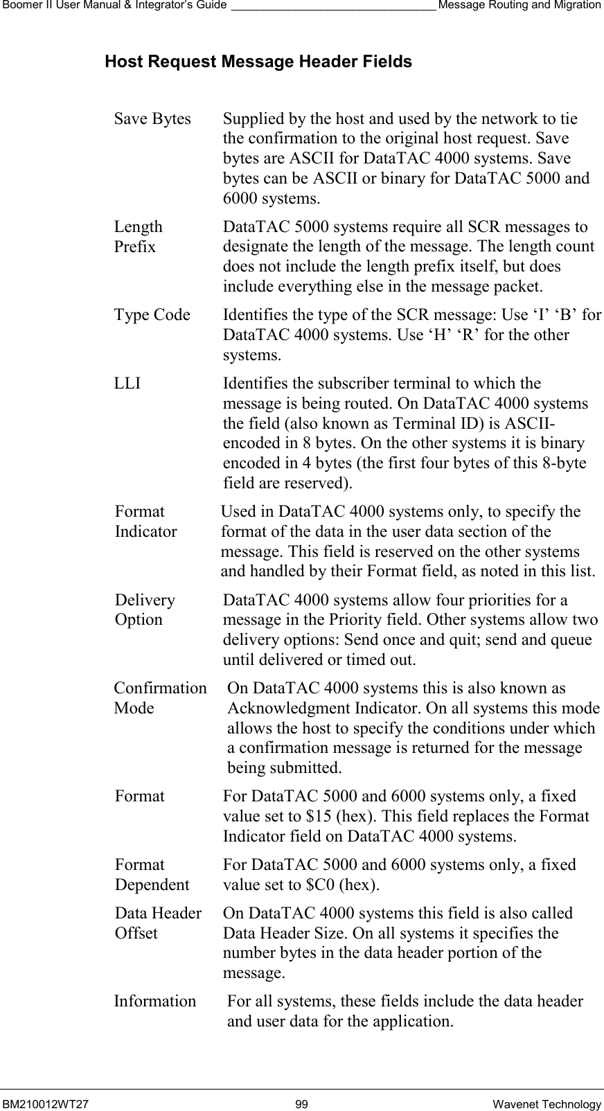
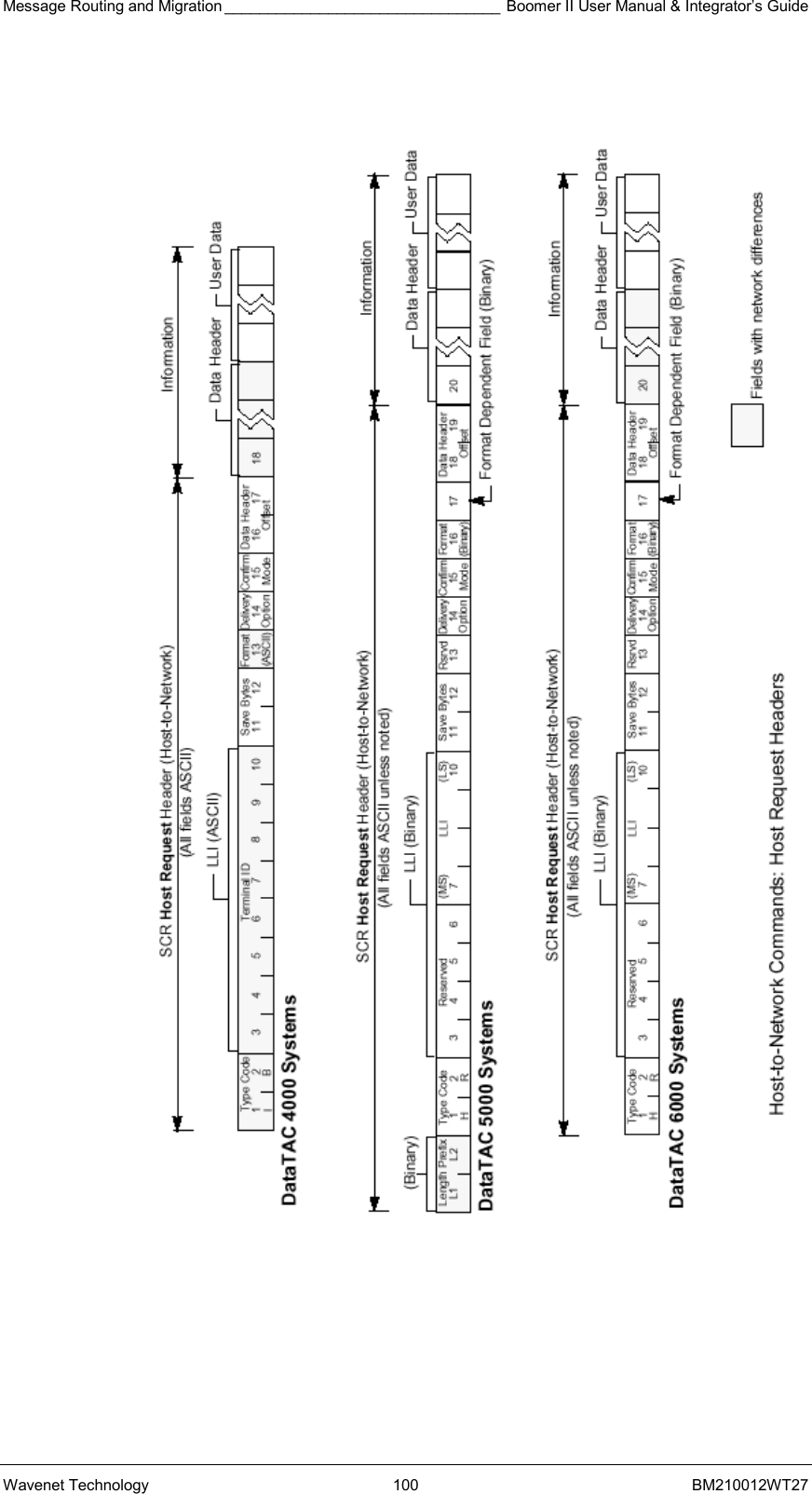
NCL INTERFACE ___________________________________________ Boomer II User Manual & Integrator’s Guide Wavenet Technology  128  BM210012WT27
Boomer II User Manual & Integrator’s Guide ______________________________________________ SDK SCRAPI BM210012WT27 129 Wavenet Technology Appendix B - Software Development Kit DataTAC networks allow wireless communication and are installed in many different countries around the world. The Wavenet Software Development Kit (SDK) has been developed to facilitate development of applications for these networks by providing a simple program interface for communicating with the network devices.  The SDK supports the following network types:   DataTAC® 4000 networks   DataTAC® 5000 networks   DataTAC® 6000 networks The SDK is made up of two major components:   Native Control Language Application Programmer's Interface (NCL API)   Standard Context Routing Application Programmer's Interface (SCR API) The NCL API is the wireless client component of the SDK. It provides routines for sending and receiving data using an NCL compliant Radio Packet Modem (RPM). The SCR API is the server component of the SDK. It provides routines for encoding and decoding of SCR protocol messages and is used for communicating with the network switch or radio network gateway (RNG). (Refer to Appendix C for details of sample programs). SDK Contents The SDK contains the following components:     Boomer II Integrators Guide (Rev 2.1).pdf   RSUSER RSUSER is a modem tool that runs in a DOS window. It will allow communication with the modem via a PC and the Boomer II Test Jig. Refer to the previous section on the Modem Test Jig for further information on the available commands. RSUSER provides a means for users to become familiar with the modem and essentially uses NCL protocol to communicate with the modem.   NCL_API:  This NCL_API requires the Microsoft Message Queue (MSMQ) service running on the target PC. MSMQ is included in Windows 2000 as part the operating system but this service needs to be activated manually. Please refer to Microsoft
SDK SCR-API ______________________________________________ Boomer II User Manual & Integrator’s Guide Wavenet Technology  130  BM210012WT27 documentation on how to activate the MSMQ service on your version of Windows. The NCL_API is built on Client-Server architecture. The NCL_API PortServer application allows multiple client applications simultaneous access to the modem via a single communications port. A sample Client Application 'ModemInfo' with full source code is also included in the NCL_API directories.    SCR_API: The Standard Context Routing Application Programmer's Interface (SCR API) is the server component of the SDK. The SCR API provides routines for encoding and decoding SCR messages for communication with the DataTAC network switch or radio network gateway (RNG). The sample application has been written to use an EICON X.25 card. To run over an X.25 connection, the sample application requires an EICON X.25 card, plus EICON WAN Services driver software. To modify and compile the sample application, or to write your own application, you will also need the EICON X.25 Development Tools for Win 32. Contact EICON Technology (www.eicon.com) for more information on these products.   \modemInfo\  A directory structure containing source files and executable for the sample ModemInfo Client application.   \PortServer\   A directory structure containing a serial port sever. The serial port server runs as a service on your PC and allows multiple Clients to access the modem via a serial port. The port server must be running for the Client applications to work. Note the port server has no user interface, and runs as a service. Run as PortServer comx:  Where "x" is the PC communication port the modem is attached to via a Boomer II Test Jig. If no command line parameter is specified, 'PortServer' assumes that  'com1' is to be used.   \VDD\  A directory structure for the VDD library containing functions required for client applications to communicate with the modem (i.e. Send, Receive etc) via MSMQ and the PortServer services. The VDD consists of the following files:   •  VDD.dll:   Dynamic Link Library. Ensure that a copy of this file is in the client's application path.  •  VDD.lib:   Library used by the linker when building client applications. •  Nclapi.h:  Header file containing the function prototypes exported by the DLL.
Boomer II User Manual & Integrator’s Guide ______________________________________________ SDK SCRAPI BM210012WT27 131 Wavenet Technology Please refer to Appendices B and C for guidance to how to use the Boomer II SDK. All code was developed using Microsoft Visual C++ Version 6.0, for Microsoft Windows WIN98/NT/2000. System Requirements This SDK requires the Microsoft Message Queue (MSMQ) service running on the target PC. MSMQ is included in Windows 2000 as part of the operating system but this service needs to be activated manually. Please refer to Microsoft documentation on how to activate the MSMQ service on Windows 2000. For all other versions of the Windows operating system, please inquire from Microsoft on how MSMQ can be installed and activated. Ensure that the PC has at least one available serial (RS-232) port before using this SDK. SDK Software Architecture The SDK is built on a client-server architecture. The server application allows multiple client applications simultaneous access to the modem The sample ‘ModemInfo’ application is an example of a client application. The ‘PortServer’ application acts as the server. Server Initialisation: Start the server application by running ‘PortServer.exe’. This server application does not have a user’s interface. The only way to ensure that it is running is to view the active processes on the Windows Task Manager. ‘PortServer.exe’ does take the desired serial port name as a  command line parameter. If no command line parameter is specified, ‘PortServer’ assumes that ‘com1’ is desired. If com2 is connected to the modem, run the server as following: PortServer com2VDD Library.  The VDD library contains all tools required for client-server communications by using the MSMQ service to deliver messages to the other party. All clients applications are required to open a session with the server application if it wants to communicate with the modem. By using the VDD library this process message delivery is transparent for the client.  NCL Application Programmer’s Interface The Native Control Language Application Programmer's Interface (NCL API) is the client component of the SDK. The NCL API provides routines for sending and receiving data messages through the DataTAC wireless network, using a radio packet modem (RPM). It also allows the client application to control configuration parameters of the RPM and to retrieve status information from the RPM. Implementation The NCL API is implemented as a DLL library of written in C++  for windows using Microsoft~ Visual C++ Version 6.0.  The NCL API communicates with PC or Pocket PC applications based
SDK SCR-API ______________________________________________ Boomer II User Manual & Integrator’s Guide Wavenet Technology  132  BM210012WT27 on the following model. The NCL API is supplied as a Virtual Device  Driver (VDD) for a PC (Win 98 or better) or a Pocket PC (Win CE  Version 3.0 or better). Multiple applications can access the RPM via  NCL encoded messages.     MSMQ  MSMQ IN N MSMQ IN 1 Layer 1 (Physical) Layer 2 (Data) )))Li k)  Layer 3  (Network) Level 4 (Transport ) Layer 6 (Presentation) Serial Port  to modem Message Router & NCL Interpreter Serial Port Drivers       TX Queue Layer 5 (Session)  Wavenet NCL API Model  Logical Architecture The following table lists the required functionality for the API per layer. The code forms a DLL, with only a subset of functions available for third party developers.  LAYER NAME  CONTENT  FUNCTION 7.  APPLICATION  Application specific data. Applications are to initialise a RX MSMQ (Microsoft Message Queuing system) queue and open a session with the VDD by passing the RX queue handler. 6. PRESENTATION LAYER  Unused   5. SESSION LAYER  Unused   4. TRANSPORT LAYER  Unused   3. NETWORK LAYER  Router MSMQ is run as a device driver on the Pocket PC and is run from power up (i.e. Non-suspend mode). The VDD will post events (RCV messages etc) to all application RX queues enabled for that event. Responses to application requests will be posted to the calling application RX queue.  The VDD process TX requests via a FIFO queue to the NCL Interpreter. The Host base routing or Peer-
Boomer II User Manual & Integrator’s Guide ______________________________________________ SDK SCRAPI BM210012WT27 133 Wavenet Technology LAYER NAME  CONTENT  FUNCTION to-Peer routing SDU formatting is contained in the NCL interpreter. 2.  DATA LINK LAYER  NCL Interpreter & Extender port – Serial Driver. Application NCL API function requests are processed via a FIFO queue. RPM responses or received data is tagged and encoded for the router as required Also the UART DLL that handles the extender port UART to modem communications resides in the link layer modules.. 1.  PHYSICAL / BIT TRANSFER LAYER   Extender Port to RPM.  9600, 8, 1, N on serial port and a wakeup line.  Wavenet’s current NCL API protocol stack is implemented with the hierarchical structure. All DLLs including MSMQ files are included in the install cabinet files for the VDD. Message Router The PC or PPC loads MSMQ as a device driver. Applications using the modem must open a session with VDD by calling ‘VDDOpen()’ which will create a private Receive MSMQ queue for the instance of the application (client). The name of this private queue will be sent to the serial port server (VDD) along with an open session request. The port server will in turn create a private MSMQ queue to receive data from the client. All Modem Events and response messages to be communicated between the VDD and the application will be via the receive queues. Transmit function requests from the applications (clients) are queued by the VDD and are processed as a FIFO buffer by the NCL interpreter. On Wakeup the VDD will be activated, if any applications receive queues are open the RX event will be posted to those queues. If no receive queues are active, the VDD will buffer the RX events and start up the registered on_wakeup applications. After the applications have successfully opened a VDD session the VDD will pass the RX events to those applications. NCL Interpreter The NCL Interpreter strips NCL API function calls from application messages, queue the calls and execute the calls on a FIFO basis. Received messages will be queued and matched against an appropriate request (if not an event), and passed to the router with the corresponding tags.  Link Layer The RPM communicates with a PC via a standard communications port and a user supplied RS232 to CMOS level device. For the Pocket PC  (PPC) the RPM communicates via the PPC extender port UART.  The PPC performs an auto detect and wakeup when an attached modem receives some data and the PPC is in suspend mode.
SDK SCR-API ______________________________________________ Boomer II User Manual & Integrator’s Guide Wavenet Technology  134  BM210012WT27 Application Interface   Opening a Session Applications are required to first open a session with the VDD by calling the API function ‘VDDOpen()’. All other API functions will return an error unless an open session with the VDD was established.   If successful this operation will result in the creation of two MSMQ queues for use by the client. One MSMQ will be used to send messages from the VDD to the client and the other for messages from the client to the VDD. Note that the client does not deal with MSMQ queues directly because all operations are wrapped in API calls.   Prototype: int VDDOpen(void)  Description: Opens a session with the VDD.   Input:   none   Output:    Return value = 0   Operation was successful   Return value  ≠ 0  Operation failed. Value specifies the error type    Close Session Applications can call this function to close its session with the VDD. An application should call this function before it terminates if a session was earlier established with the VDD.  The reason for this is to ensure that all created MSMQ queues for the client are deleted. This will prevent irrelevant/outdated messages from being posted to inactive MSMQ queues.  Prototype: int VDDClose(void);  Description: Close a session with the VDD.
Boomer II User Manual & Integrator’s Guide ______________________________________________ SDK SCRAPI BM210012WT27 135 Wavenet Technology Input:   None   Output:    Return value = 0   Operation was successful   Return value  ≠ 0  Operation failed. Value specifies the error type    Send Data to a Radio Host Applications can call this function to send data to a radio host. The Host ID will automatically be inserted into the data header of the SDU for message routing purposes.    Prototype: int nclSendData(word *usSduTag, byte *szHostId, byte ucIdLen, byte *ucData, int iDatLen, bool bResend);  Response:  The VDD will track the response with the Host ID and SDU tag will post the response to the corresponding RX queue for that session. The application is responsible for reading and processing the response on the RX queue. By calling ‘nclReceiveData()’.   Description: Send application data to the radio host identified by the host ID.   Input:   usSduTag  Pointer to a word where the SDU tag can be stored   szHostId  Pointer to a buffer specifying the Host identity. The Host ID is typically 3 bytes in length for DataTac systems. The NCL API will truncate Host ID’s longer than NCL_MAX_UH_LEN (63) bytes in length.   ucIdLen  Total length of the session ID   ucData  Pointer to the data to be sent   iDatLen  Length of the data to be sent   bResend  Resend flag must be set to false, except if the packet of data is being re-sent due to a failure of the previous send. Setting the flag to true prevents the possibility of receiving duplicate packets at the server application. This flag cannot be used for resending data prior to the previous packet.
SDK SCR-API ______________________________________________ Boomer II User Manual & Integrator’s Guide Wavenet Technology  136  BM210012WT27 Output:    Return value = 0   Operation was successful   Return value  ≠ 0  Operation failed. Value specifies the error type   usSduTag  Pointer to a word containing a reference of the corresponding SDU tag which was generated by the NCL API for this command to the RPM.    Receive Data From RPM Applications can call this function to obtain data sent from the RPM. This applies to both event and response type data from the RPM. Note this is the only way to obtain response data originating from the RPM as a result of issuing commands to it by means of other API functions described in this document. The return code of all API functions issuing commands to the modem only provides feedback about the posted command. It does not guarantee delivery to the RPM. It is thus imperative for applications to use ‘nclReceiveData()’ to obtain feedback directly from the RPM on commands sent to it. Responses to commands are asynchronous meaning multiple commands can be issued to the RPM before the application needs to look at all the responses.  This is the reason why every command provides the application with a copy of the unique SDU tag generated for the command. Every response message contains the same SDU tag of its associated command. The VDD uses the SDU tag to route response messages to the originating application (client). The  ‘nclReceiveData()’ function provides the SDU tag of the response message. Applications can use these tags to tie up responses with previously sent commands.  One notable exception exist when the SDU tag is equal to 65535 (FFFF hexadecimal). Only event messages contain an SDU tag equal to 65535. The received event/ response messages will be represented as an array of bytes which must be typed cast to a structure identified by returned structure ID.   The RCV_MSG_NOTIFICATION event will be handled by the VDD, which will read the messages from the RPM and pass the messages to all clients with open sessions.  Other Event types shall be posted to all clients with open sessions  registered for that event. If no applications are registered for that event the event will be disabled in the modem.  Prototype: int nclReceiveData(DWORD dwTimeOut, BYTE *ucStructId, WORD *usSduTag,  int *iBufLen, BYTE *ucBuf);  Description: Receive messages from the RPM.
Boomer II User Manual & Integrator’s Guide ______________________________________________ SDK SCRAPI BM210012WT27 137 Wavenet Technology  Input:   dwTimeOut  The time (in milliseconds) to wait for the next message. Use 0 to return immediately or FFFFFFFF (hexadecimal) to hang on indefinitely for a message. The calling thread will be suspended until a message arrive or the time-out period has elapsed, whichever occurs first.   ucStructId  Pointer to a byte where the structure ID can be stored.    usSduTag  Pointer to a word where the SDU tag can be stored   iBufLen  Pointer to a integer specifying the total size of ucBuf.   ucBuf  Pointer to the buffer (of size iBufLen) where receive data can be placed  Output:    Return value = 0   Operation was successful   Return value  ≠ 0  Operation failed. Value specifies the error type   ucStructId  This value identifies the structure of the data in ucBuf. See the following paragraphs for details.   usSduTag  Pointer to a word containing a reference of the corresponding SDU tag which was generated by the NCL API for this command to the RPM.   iBufLen  Size (in bytes) of the data in ucBuf. Note: Buffer lengths of 0 is possible – rely solely on the return value in such cases   ucBuf  Pointer to buffer containing the received data  /*** Define types for retrieving data from the RPM ***/  typedef unsigned char       BYTE; typedef unsigned short      WORD;  /*Parameter Structure IDs - Do not alter sequence*/ enum {   NCLNone_ID = 0,  NCLEvent_ID,  NCLProdId_ID,  NCLVersion_ID,  NCLRpmId_ID,   NCLConfigBlock_ID,    NCLStatusBlock_ID,    NCLChanBlock_ID,   NCLGroupLlis_ID,   NCLChannelTable_ID,    NCLWaveSettings_ID,  NCLWaveRadio_ID,  NCLWaveGen_ID,  NCLByte_ID,  NCLByte2_ID,  NCLWord_ID,  NCLMsg_ID,  NCLRaw_ID   /*additional structure IDs to be added here including vendor specific types */
SDK SCR-API ______________________________________________ Boomer II User Manual & Integrator’s Guide Wavenet Technology  138  BM210012WT27 };  /* Use 1 byte alignment for the following structures */ #pragma pack(1)   /* Product ID structure */ typedef struct NCLProdId {  BYTE hw_platform;  BYTE rf_protocol;  BYTE ncl_compliance;  BYTE release_level; }NCLProdId;  /* NCL version structure */ typedef struct NCLVersion {  char major[2];  char minor[2]; }NCLVersion;   /* RPM ID structure */ typedef struct NCLRpmId {  BYTE  b_val[4]; }NCLRpmId;   /* Config block structure */ typedef struct NCLConfigBlock {  NCLProdId  prod_id;  NCLVersion  sw_version;  NCLRpmId  rpm_id;  WORD   reserved;  WORD   max_data_size; }NCLConfigBlock;   /* Status block structure */ typedef struct NCLStatusBlock  {  BYTE   rx_status;  BYTE   tx_status;  BYTE   antenna;  BYTE   radio_in_range;  BYTE   flow_control;  BYTE   rcv_mode;  BYTE   event_states;  WORD   ob_msg_count;  WORD   ib_msg_count;  WORD   radio_channel; }NCLStatusBlock;   /* Channel block structure */ typedef struct NCLChanBlock {
Boomer II User Manual & Integrator’s Guide ______________________________________________ SDK SCRAPI BM210012WT27 139 Wavenet Technology  BYTE   radio_in_range;  WORD   radio_channel;  BYTE   attribute;  BYTE   protocol;  BYTE   rssi; }NCLChanBlock;  #define MAX_GROUP_LLIS     8 #define LLI_BYTE_WIDTH      8 #define NCL_NUM_CHANNELS  64  /* Group LLIs array */ typedef struct NCLGroupLlis {     BYTE  lli[MAX_GROUP_LLIS][LLI_BYTE_WIDTH];     BYTE  num; }NCLGroupLlis;   /* Channel Table */ typedef struct NCLChannelTable {     WORD      channel[NCL_NUM_CHANNELS];     BYTE            num; }NCLChannelTable;  /* Vendor Spesific: Wavenet Get Settings*/ typedef struct NCLWaveSettings {  BYTE   LLI[4];  BYTE   SerNum[16]; } NCLWaveSettings;  /* Vendor Spesific: Wavenet Get Radio Settings*/ typedef struct NCLWaveRadio {  BYTE   rssi[2];  BYTE   reserved1;  BYTE   reserved2;  BYTE   reserved3;  BYTE   reserved4;  BYTE   reserved5;  BYTE   reserved6;  BYTE   reserved7;  BYTE   reserved8;  BYTE   frequency[4];  BYTE   channel[2];  BYTE   base_id; } NCLWaveRadio;  /* Vendor Spesific: Wavenet Generic*/ typedef struct NCLWaveGen {  BYTE   byte[100]; } NCLWaveGen;  /* NCL status information structure */ typedef union NCLStatus {  NCLProdId  prod_id;  BYTE   vendor_id;  NCLVersion  sw_version;  NCLRpmId  rpm_id;
SDK SCR-API ______________________________________________ Boomer II User Manual & Integrator’s Guide Wavenet Technology  140  BM210012WT27  BYTE   rpm_vid[2];  NCLGroupLlis  rpm_gid;  WORD   max_data_size;  BYTE   rx_status;  BYTE   tx_status;  BYTE   antenna;  BYTE   radio_in_range;  WORD   ob_msg_count;  WORD   ib_msg_count;  BYTE   flow_control;  BYTE   rcv_mode;  BYTE   event_states;  WORD   radio_channel;  NCLChannelTable  chan_table;  NCLChannelTable dchan_table;  NCLConfigBlock config_block;  NCLStatusBlock status_block;  NCLChanBlock  chan_block;  BYTE   bat_level;  NCLWaveSettings wave_set;  NCLWaveRadio  wave_radio;  NCLWaveGen  wave_generic; }NCLStatus;  /* Event Type */ typedef struct NCLEventType {     BYTE   etype;     /* NCL_RCV_MSG_DATA  'A'  Received message data               */     /* NCL_MSG_NOTIFICATION     ‘B’  Received Message notification     */     /* NCL_TX_EVENT      'C'   Transmitter event                          */     /* NCL_RX_EVENT      'D'   Receiver event                              */ /* NCL_HW_EVENT      'E'   Hardware event                            */ /* NCL_RCV_ERR_EVENT    'F'   Unreceivable Message Event       */ /* NCL_CONTROL_EVENT    'G'   Control Event                                */      BYTE  EventCode;     /* NCL_MSG_NOTIFICATION_LEN  N- Number of buffered msgs to be read   */     /* NCL_TX_EVENT_KEYED  ‘1’  Transmitter keyed                         */ /* NCL_TX_EVENT_DEKEYED  ‘2’  Transmitter dekeyed                     */ /* NCL_RX_EVENT_INRANGE  ‘1’  RF in range                                   */ /* NCL_RX_EVENT_OUTRANGE ‘2’  RF out of range                             */ /* NCL_RX_EVENT_PSENAB  ‘3’  Power Save enabled                     */ /* NCL_RX_EVENT_PSDISAB  ‘4’  Power Save disabled                     */ /* NCL_HW_EVENT_STEST  ‘1’  Self Test Failed                             */ /* NCL_HW_EVENT_LBATT  ‘2’  Low battery                                    */ /* NCL_HW_EVENT_MFULL  ‘3’  Memory Full                                   */ /* NCL_HW_EVENT_BATOK  ‘4’  Battery Level OK                */ /* NCL_HW_EVENT_MEMOK  ‘5’  Memory Ok                       */ /* NCL_HW_EVENT_MEMOK  ‘6’  Device shutdown is imminent        */ /* NCL_RCV_ERR_EVENT_RTD  ‘1’  ACK required PDU received but TX disabled */                           /* NCL_CONTROL_EVENT_C  ‘1’  RPM / DTE connected                   */  }NCLEventType;   /* RCV_MSG_Data  */ #define NCL_MAX_DATA_SIZE    2048 #define NCL_MAX_UH_LEN      63  /* max length of user header */
Boomer II User Manual & Integrator’s Guide ______________________________________________ SDK SCRAPI BM210012WT27 141 Wavenet Technology  typedef struct NCLMsg  {     BYTE        is_message; /* If FALSE, only len and buf components are valid.  */     BYTE        sessionID[NCL_MAX_UH_LEN + 1]; /* NULL terminated */     BYTE        msg_type;   /* Used by NCL_DATATAC_5000 networks */     WORD      len;     BYTE        buf[NCL_MAX_DATA_SIZE]; } NCLMsg;                    /* End of 1 byte alignment */ #pragma pack()   Get RPM Status Information The application can call this function to obtain status information about the RPM. The following types of status information can be obtained:  Status Request (non vendor specific) Response Structure  Description NCL_R_CONFIG_BLOCK   NCLConfigBlock  Get RPM configuration block  NCL_R_STATUS_BLOCK   NCLStatusBlock  Get RPM status block  NCL_R_PROD_ID   NCLProdId  Get RPM product ID  NCL_R_SW_VERSION   NCLVersion  Get software version number  NCL_R_RPM_ID   NCLRpmId  Get RPM address  NCL_R_RPM_VID   NCLStatus.rpm_vid[2]  Get RPM VID address (MDC)  NCL_R_MAX_DATA_SIZE   NCLStatus.max_data_size  Get SDU data limit  NCL_R_RCV_MODE   NCLStatus.rcv_mode  Get mode of notification to DTE for received SDUs.  NCL_R_RX_STATUS   NCLStatus.rx_status  Get receiver enable status  NCL_R_TX_STATUS   NCLStatus.tx_status  Get transmitter enable status  NCL_R_ANTENNA   NCLStatus.antenna  Get antenna selection status  NCL_R_RADIO_IN_RANGE   NCLStatus.radio_in_range  Get radio in range status  NCL_R_OB_MSG_COUNT   NCLStatus.ob_msg_count  Get count of outbound   messages queued  NCL_R_IB_MSG_COUNT   NCLStatus.ib_msg_count  Get count of inbound  NCL_R_FLOW_CONTROL   NCLStatus.flow_control  Get flow control status  NCL_R_EVENT_STATES   NCLStatus.event_states  Get current event reporting  (enable/disable) state  NCL_R_RADIO_CHANNEL   NCLStatus.radio_channel  Get current radio channel  NCL_R_CHAN_TABLE   NCLChannelTable  Read radio channel table  NCL_R_CHAN_BLOCK   NCLChanBlock  Read the channel block NCL_R_BAT_LEVEL   NCLStatus.bat_level  Read the battery level NCL_R_RPM_GID   NCLGroupLlis  Get RPM group IDs NCL_R_VENDOR_ID   NCLStatus.vendor_id  Get vendor identification NCL_R_DCHAN_TABLE   NCLChannelTable  Read the D-channel table NCL_R_RF_STATISTICS   Specific to RF protocol used: RD-LAP [F] or MDC [G] Read the RF statistics
SDK SCR-API ______________________________________________ Boomer II User Manual & Integrator’s Guide Wavenet Technology  142  BM210012WT27   Status Request (Wavenet Technology specific) Response Structure  Description WN_GET_STATUS_RADIO  NCLWaveRadio  Get RPM Radio Status  WN_GET_STATUS_BATTERY  NCLWaveGen  Get RPM Battery Status WN_GET_STATUS_ONTIME  NCLWaveGen  Get RPM on-time status WN_GET_STATUS_CONFIG  NCLWaveGen  Get RPM configuration status   Prototype: int nclGetStatus (word *usSduTag, byte ucVendor, byte ucType, byte ucRequest);  Description: Command the RPM to send the requested status information.   Input:   usSduTag  Pointer to a word where the SDU tag can be stored   ucVendor Vendor identifier. Use: NCL_NO_VEND = 0 if not vendor specific or  NCL_VEND_WAVENET = ’F’ for Wavenet Technology specific requests    ucType  The type of status information to retrieve from the RPM (Used by Vendor specific requests). Set to zero for non-vendor requests or  WN_GET_STATUS = ‘?’ for Wavenet Technology specific requests   ucRequest  The requested status information, as listed in one of the appropriate tables above, to retrieve from the RPM.  Output:    Return value = 0   Operation was successful   Return value  ≠ 0  Operation failed. Value specifies the error type   usSduTag  Pointer to a word containing a reference of the corresponding SDU tag which was generated by the NCL API for this command to the RPM.  The response is posted to the corresponding RX queue associated with the VDD session ID. If the session ID is not recognized all active RX queues will be posted the response.
Boomer II User Manual & Integrator’s Guide ______________________________________________ SDK SCRAPI BM210012WT27 143 Wavenet Technology   Set Configuration ITEMS Within the RPM By default the modem will have the receiver and transmitter enabled and the RX notification event enabled. Modem Configuration items via NCL are TBA and will be restricted to service personnel.   Reset RPM The application can call this function to reset the RPM. There are several different levels of RPM reset commands that may be issued to the RPM, as listed below:   Reset Level  Description NCL_RESET_INBOUND   Flush the Inbound queue  NCL_RESET_OUTBOUND   Flush the Outbound queue NCL_RESET_BOTH   Flush both the Inbound and Outbound queues NCL_RESET_WARM  Warm start: flush queues, default Native settings, remain in Native mode NCL_RESET_TRANS   Not Supported NCL_RESET_FULL   Full reset: Power-on reset NCL_RESET_NCL   Reset NCL interpreter NCL_RESET_OFF   Power off the RPM  Prototype: int nclResetRPM (word *usSduTag, byte ucResetLevel);  Description: Command the RPM to perform a specified level reset   Input:   usSduTag  Pointer to a word where the SDU tag can be stored   ucResetLevel  The level of the Reset as listed in the above table  Output:    Return value = 0   Operation was successful   Return value  ≠ 0  Operation failed. Value specifies the error type   usSduTag  Pointer to a word containing a reference of the corresponding SDU tag which was generated by the NCL API for this command to the RPM.  The response is posted to the corresponding RX queue associated with the VDD session ID. If the session ID is not recognized all active RX queues will be posted the response.
SDK SCR-API ______________________________________________ Boomer II User Manual & Integrator’s Guide Wavenet Technology  144  BM210012WT27   Register Event Callback Function Since the RX events will be posted to private Receive MSMQ queues the VDD is not required to support callback functions. Applications can call the API function ‘nclReceiveData()’, to wait on response and event messages from the RPM on their on account. The API function ‘nclReceiveData()’ will return within the time-out period specified, so applications will not be hung-up indefinitely.    Enable / Disable Events The application can call this function to enable or disable individual event types being reported by the RPM. By default, only the Receive Message Data event is enabled (NCL_RCV_MSG_DATA). All other event types for an application are disabled unless they have been specifically enabled / disabled using this function. The NCL_RCV_MSG_NOTIF event is handled by the VDD, which will post the received messages to all active RX queues (that have NCL_RCV_MSG_DATA enabled) using the NCLRXDataID structure type.  Prototype: int nclSetEvent (word *usSduTag, byte ucType, byte ucSetting);  Description: Enable / Disable event reporting by the RPM for the specified event type.   Input:   iSessionID  VDD session ID   usSduTag  Pointer to a word where the SDU tag can be stored   ucType  The type of event to enable/disable: NCL_RCV_MSG_DATA    (Received message data)  NCL_TX_EVENT (Physical-level transmitter event) NCL_RX_EVENT (Physical-level receiver event) NCL_HW_EVENT  (Hardware event) NCL_RCV_ERR (Un-receivable message event) NCL_CONTROL  (Control event) NCL_VEND_EVENT  (Vendor specific event)   ucSetting  NCL_DISABLE     (Disable event reporting) NCL_ENABLE      (Enable event reporting)  Output:    Return value = 0   Operation was successful   Return value  ≠ 0  Operation failed. Value specifies the error type
Boomer II User Manual & Integrator’s Guide ______________________________________________ SDK SCRAPI BM210012WT27 145 Wavenet Technology   usSduTag  Pointer to a word containing a reference of the corresponding SDU tag which was generated by the NCL API for this command to the RPM.    Get Error Description The application can call this function to obtain a string representation for a specified error code.   Error Code  Value  Description NCL_ERR_NONE  0  No error has occurred NCL_ERR_SESSION_IS_CLOSED  -1  NCL API: Session has not been opened NCL_ERR_SESSION_IS_OPEN  -2  NCL API: Session is already open NCL_ERR_ENCODE    -3  NCL API: NCL Frame encoding error  NCL_ERR_DECODE    -4  NCL API: NCL Frame decoding error NCL_ERR_PARAM  -5  NCL API: Invalid parameter passed NCL_ERR_TIMEOUT  -6  NCL API: Time-out elapsed waiting for response NCL_ERR_MSMQ_OPEN  -7  NCL API: An error occurred opening a MSMQ NCL_ERR_MSMQ_CLOSE  -8  NCL API: An error occurred closing a MSMQ NCL_ERR_MSMQ_SEND  -9  NCL API: An error occurred sending a MSMQ NCL_ERR_MSMQ_RECEIVE  -10  NCL API: An error occurred receiving a MSMQ NCL_ERR_MSMQ_CREATE  -11  NCL API: An error occurred creating a MSMQ NCL_ERR_MSMQ_DELETE  -12  NCL API: An error occurred deleting a MSMQ NCL_ERR_MSMQ_NAME  -13  NCL API: An error occurred searching for a MSMQ NCL_ERR_MAX_CLIENTS  -14  NCL API: Maximum number of supported clients reached NCL_ERR_INVALID  'b'  NCL Syntax error: Invalid options  NCL_ERR_TOO_LONG  'c'  NCL Syntax error: Data too long NCL_ERR_ES_NAME  'd'  NCL Syntax error: Invalid name  NCL_ERR_NO_RESPONSE    'A'  Execution error: No response from network NCL_ERR_NO_ACK  'B'  Execution error: Negative ACK received  NCL_ERR_HOST_DOWN  'C'  Execution error: Host down NCL_ERR_NOT_REGISTERED  'D'  Execution error: RPM not registered  NCL_ERR_LOW_BATTERY   'E'  Execution error: Low battery - can't transmit NCL_ERR_IBQ_FULL  'F'  Execution error: RPM inbound queue full  NCL_ERR_TX_DISABLED  'G'  Execution error: Radio transmitter disabled  NCL_ERR_BUSY  'H'  Execution error: Resource unavailable  NCL_ERR_NOT_AVAILABLE  'I'  Execution error: Unimplemented services  NCL_ERR_HW_ERROR   'J'  Execution error: Generic NCL_ERR_INVALID_MODE  'K'  Execution error: Invalid mode of operation  NCL_ERR_NO_MESSAGES  'L'  Execution error: No outbound messages available NCL_ERR_MSGS_PENDING  'M'  Execution error: Pending inbound messages NCL_ERR_SW_ERROR  'N'  Execution error: Software error has been encountered NCL_ERR_OUT_OF_RANGE   'O’  Execution error: Cannot send data when out of
SDK SCR-API ______________________________________________ Boomer II User Manual & Integrator’s Guide Wavenet Technology  146  BM210012WT27 Error Code  Value  Description range NCL_ERR_PACKET_ERROR    'Z'  Execution error: SDU data corruption detected Error Not Listed  All other values Unknown error  Prototype: char * nclGetErrorDescription (int iErrorCode);  Description: Return a pointer to a character string describing the specified error code.   Input:   iErrorCode  Integer specifying the error code for which a string description is required.  Output:    WCHAR *   Pointer to a NULL terminated wide character (Unicode) string describing the error    Register Wakeup Application By default the VDD is executed on wakeup. In addition an application can register to be executed on wakeup via the VDD. On wakeup the VDD will post any Received data to the current active queues. If there are no active queues the VDD will execute the Registered applications. Once an application has initiated a successful VDD session (i.e. via ‘VDDOpen ()’ ) the VDD will post the Received data to the applications RX queue. A timeout (Wktm = 10 seconds) will be used to hold the data for an application to initialize and commence a VDD session before the data is discarded. The default application will be the Modem Information application as supplied as a sample application with the VDD.    Prototype: int nclRegWakeupApp (WCHAR *usAppName, WORD usWakeupReason);  Description: Register an application for wakeup when specified events occur.
Boomer II User Manual & Integrator’s Guide ______________________________________________ SDK SCRAPI BM210012WT27 147 Wavenet Technology Input:   usAppName  Pointer to a buffer specifying the full path name (Null terminated) of the application to execute on a wakeup.   usWakeupReason  Logical OR the required reasons for wakeup from the following values (exclude unwanted reasons): WAKE_MODEM_INSERTION – Wakeup application when modem is attached WAKE_MESSAGE_RECEIVED – Wakeup application when a message is received but no client applications are running  Output:    Return value = 0   Operation was successful   Return value  ≠ 0  Operation failed. Value specifies the error type    Deregister Wakeup Application The application can call this function to deregister an application that was previously registered to wakeup.    Prototype: int nclDeregWakeupApp (WCHAR *usAppName);  Description: Deregister a wakeup application.  Input:   usAppName  Pointer to a buffer specifying the full path name (Null terminated) of the application to execute on a wakeup.  Output:    Return value = 0   Operation was successful   Return value  ≠ 0  Operation failed. Value specifies the error type    Switch RPM On/Off The application can call this function to switch the RPM on or off.    Prototype: int nclSwitchRPMPower (word usSetting);  Description: Switch the RPM power to the desired setting.
SDK SCR-API ______________________________________________ Boomer II User Manual & Integrator’s Guide Wavenet Technology  148  BM210012WT27  Input:   usSetting  If this value is zero, the RPM should power down else it should power up  Output:    Return value = 0   Operation was successful   Return value  ≠ 0  Operation failed. Value specifies the error type    Send Generic NCL Command To RPM The application can call this function to send application specific commands to the RPM.    Prototype: int nclSendGenericCommand (WORD *usSduTag, BYTE ucLength, BYTE *ucParam);  Description: Send an NCL command to the RPM of which the payload contents consist of data from the specified buffer. Input:   usSduTag  Pointer to a word where the SDU tag can be stored   ucLength  Pointer to a byte specifying the total size of ucParam.   ucParam  Pointer to the buffer (of size ucLength) containing the data to be send to the RPM  Output:    Return value = 0   Operation was successful   Return value  ≠ 0  Operation failed. Value specifies the error type    Get Software Version The application can call this function obtain the software version of the server application or the VDD DLL.    Prototype: int VDDgetVersion (WORD* usVersion); Description: Obtain the software version of the specified software entity. Input:
Boomer II User Manual & Integrator’s Guide ______________________________________________ SDK SCRAPI BM210012WT27 149 Wavenet Technology   usVersion  Set this value to zero to request the VDD DLL version or to any other value to request the server application version  Output:    Return value = 0   Operation was successful   Return value  ≠ 0  Operation failed. Value specifies the error type   usVersion  The upper 8 bits contain the major version and the lower 8 bits contain the minor software version if the return value is zero  SCR Application Programmer’s Interface The Standard Context Routing Application Programmer's Interface (SCR API) is the server component of the SDK. The SCR API provides routines for encoding and decoding SCR messages for communication with the DataTAC® network switch or radio network gateway (RNG). Decoded SCR messages are stored in structures defined to represent SCR messages. Encoded messages are stored in memory buffers. To encode a message, an application will first set up a structure representing the desired SCR message. This structure is then passed to the encoding function, scr_Encode(), which encodes the message into a memory buffer. The application can then send this encoded message to the DataTAC network switch or RNG. To decode an SCR message received from the network switch, the application passes the received message buffer to the decode routine, scr_Decode(), which decodes the message into a structure containing the data from the message. Routines are also provided to convert some of the message codes into English language descriptions of the code. The SCR API does not contain routines for reading the SCR messages from the message switch interface or for sending encoded SCR messages to the message switch. The connection to the message switch is normally via an X.25 connection or a TCP/IP connection. When you are using an X.25 connection to the network switch or RNG, communication will be via an X.25 card. You will need to get an X.25 and appropriate drivers for this card. To develop your own application, you will also need the developer's kit for your X.25 card. The sample application has been written to use an EICON X.25 card. To run over an X.25 connection, the sample application requires an EICON X.25 card, plus EICON WAN Services driver software. To modify and compile the sample application, or to write your own application, you will also need the EICON X.25 Development Tools for Win 32. Contact EICON Technology (www.eicon.com) for more information on these products.
SDK SCR-API ______________________________________________ Boomer II User Manual & Integrator’s Guide Wavenet Technology  150  BM210012WT27 When you are using a TCP/IP connection to the network switch or RNG, communication will be via some form of TCP/IP link. This may be via an Ethernet card or through a modem connection running SLIP or PPP. The appropriate drivers will need to be configured for the Ethernet card, and TCP/IP will need to be configured as a network protocol. Contact your hardware supplier for more details on configuring the TCPm connection. To communicate through the TCP/IP connection, the sample application uses the standard Winsock interface provided with the Microsoft Windows operating system. Most Windows compilers come with a standard developer's kit to interface to the Winsock routines. Implementation The SCR API is implemented as a library of routines written in ANSI C and compiled for Windows NT using the Microsoft Visual C++ compiler. All default project settings were used to compile the .lib file. SCR Structures The SCR API makes use of several important structures to store the SCR messages. The main structure is the SCRMsg structure. This structure is a union of structures, each of which represents a single message type in the SCR protocol.  The SCRMsg structure is shown here. The msg_type field indicates which element of the union is valid. The appropriate value for the msg_type field is shown in the comments.  /* The SCR Message data structure. */ typedef struct SCRMsg {  int msg_type;  union{   SCRhrr r;   /*msg_type: SCR_HR*/   SCRar  ar;  /*msg_type: SCR_AR*/   SCRlr  lr;  /*msg_type: SCR_LR*/ SCRhc  hc;  /*msg_type: SCR_HC*/ SCRac  ac;  /*msg_type: SCR_AC*/ SCRlc  lc;  /*msg_type: SCR_LC*/ SCRmi  mi;  /*msg_type: SCR_MI*/ SCRci  ci;  /*msg_type: SCR_CI*/ SCRdi  di;  /*msg_type: SCR_DI*/ SCRrs  rs;  /*msg_type: SCR_RS*/ SCRrr  rr;  /*msg_type: SCR_RR*/ SCRib  ib;  /*msg_type: SCR_IB*/ SCRob  ob;  /*msg_type: SCR_OB*/ SCRab  ab;  /*msg_type: SCR_AB*/ SCRreqstat reqstat;   /*msg_type: SCR_REQ_STAT*/ SCRstatrsp statrsp;  /*msg_type: SCR_STAT_RSP*/ SCRtonet tonet;   /*msg_type: SCR_TO_NET*/ SCRfromnet fromnet;  /*msg_type: SCR_FROM_NET*/ SCRack  ack;  /*msg_type: SCR_ACK*/  } u; } SCRMsg;
Boomer II User Manual & Integrator’s Guide ______________________________________________ SDK SCRAPI BM210012WT27 151 Wavenet Technology Definitions for all SCR message structures can be found in the file scrapi.h. (SCR SDK) Network Independent Messages The SCR API provides several network independent message types. These message types represent basic functions within the SCR protocol that are applicable to all DataTAC network types. The SCR API encodes and decodes these message types as the appropriate message for the correct network type, as given in the call to the scr_Init() function. It is recommended that you use these network independent message types wherever possible, to enhance the portability of the code between different DataTAC network versions. The three network independent message types are listed here: SCR_FROM_NET  Generic From Network message. This is used for receiving data from a wireless device. Depending on the network setting, this corresponds to either a Basic Outbound (OB) message for DataTAC 4000 networks, or a Message Indication (MI) for DataTAC 5000 or 6000 networks. SCR_TO_NET  Generic To Network message. This is used for sending data to a wireless device. Depending on the network setting, this will be encoded as either a Basic Inbound (IB) message for DataTAC 4000 networks, or a Host Request (HR) message for DataTAC 5000 or 6000 networks. SCR_ACK  Generic Acknowledgment message. This is used to receive an acknowledgment for data sent to a wireless device. SCR_TO_NET messages may be passed to scr_Encode(), and they will be encoded as the appropriate message type for the current network, as set in the call to scr_Init(). When a received packet is decoded using scr_Decode(), it converts the received packet to an SCRMsg structure. The received messages are decoded for the current network type, and stored in the SCRMsg structure as their actual message type. However, the definition of the generic From Network message structure, SCRfromnet, is exactly the same as both the Message Indication (MI) message structure, SCRmi, and the Basic Outbound (OB) message structure, SCRob. Because of this, the decoded message structure may be interpreted as any of these structures. Similarly, the message type values SCR_FROM_NET, SCR_MI, and SCR_OB are defined to be the same value. Also, the message types SCRack, SCRhc, and SCRab are all the same, and the message-type constants SCR_ACK, SCR_HC, and SCR_AB are all the same, and so may be interpreted interchangeably.
SDK SCR-API ______________________________________________ Boomer II User Manual & Integrator’s Guide Wavenet Technology  152  BM210012WT27 Coupled with the interchangeable use of the message structures SCRack, SCRhc, and SCRab is the function scr_NakReasonText(). The response code field within the SCRack structure is network specific, but the scr_NakReasonText() function will interpret the response code appropriately for the network type specified to scr_Init() and will return a text description of the error code, or a NULL pointer if the code represents successful delivery. Network Specific Messages The SCR API defines network specific message structures for each of the network specific SCR message types. These messages apply only to particular versions of the DataTAC network. When a message is passed to the scr_Encode() routine, and that message is not valid for the specified network type, it is encoded as the corresponding message type for the network version specified to scr_Init() wherever possible. For example, if scr_Init() is used to set the network type to DataTAC 5000, and an SCR_IB message is passed to scr_Encode(), it will be encoded as a Host Request (HR) message. Also, due to the same structure definitions and equivalent message type constants being used across all network types for the From Network (OB and MI) and Acknowledgment (AB and HC) messages, the decoded structures may be interpreted as network specific structures, and this will still work on other network types. For example, if scr_Init() is used to set the network type to DataTAC 5000, and a SCR_MI message is received from the network and decoded, this decoded structure may be interpreted as an SCR_OB structure with no side effects.  DataTAC® 4000 Network Messages The following message types are specific to the DataTAC 4000 network: SCR_OB  Basic Outbound message for receiving data from a wireless device SCR_IB  Basic Inbound message for sending data to a wireless device SCR_AB  Basic Acknowledgment of data sent to a wireless device  DataTAC® 5000 Network Messages The following message types are extended SCR messages that are only used on the DataTAC 5000 network. SCR_LR Loopback Request SCR_LC  Loopback Confirmation (response to LR) SCR_CI Connect Indication
Boomer II User Manual & Integrator’s Guide ______________________________________________ SDK SCRAPI BM210012WT27 153 Wavenet Technology SCR_DI Disconnect Indication SCR_AR Activity Request SCR_AC  Activity Confirmation (response to AR) SCR_RS Receiver Suspend SCR_RR Receiver Resume  DataTAC® 5000 and DataTAC® 6000 Network Messages The following message types are common to the DataTAC 5000 and 6000 networks: SCR_MI  Message Indication message for receiving data from a wireless device. SCR_HR  Host Request message for sending data to a wireless device SCR_HC  Host Confirmation for acknowledgment of data sent to a wireless device Data Header All data messages (MI, HR, OB, IB, TO_NET, FROM_NET) contain a data header field. This field is used to route messages to the correct server from client RPM devices. The data header is also sometimes referred to as the session, and this is reflected in some of the NCL API function parameters. For example, the szHostId parameter in nclSendData and in  the data header for the nclReceiveData functions. This data header is represented in the SDK as a NULL terminated string. Refer to section Message Routing and Migration sub section SCR Header charts for the formatting of the header fields. How the use of the Data Header field varies between the network types is described below. For DataTAC 4000 and 6000 networks, a host slot is used to route data from the wireless client to the correct server. RPM devices can be configured with up to five host slots, each routed to a different server application. When the client application sends a message, the data header is used to specify which host slot to send on, and hence which server application the data will be sent to. The host slot is represented by a single ASCII digit from 1 to 5. This digit must be given as the last character of the data header. For example, a data header of I would route the information on host slot 1, whereas a data header of TE3 would route the data on host slot 3. For the DataTAC 5000 network, a 2-character session ID is used for routing data from the wireless client to the correct server. RPM devices may be configured with many sessions, each routed to different server applications. The session ID is made up of any two characters from A to Z or 0 to 9. When a client application sends data to a server
SDK SCR-API ______________________________________________ Boomer II User Manual & Integrator’s Guide Wavenet Technology  154  BM210012WT27 application, it must set the first two characters of the data header to the session number. For example, a data header of Al routes data on session A1, and a data header of TEI routes data on session TE. To simplify porting of applications between different network types, the use 3-character data headers, such as TEI. Using a data header of this format, DataTAC 4000 and 6000 networks look only at the last character of the data header and route on host slot 1, while a DataTAC 5000 network will look at the first two characters and route on session TE. This allows the same data header to be used on all network types. It is recommended that the data header is also set for messages from server to client. This is not critical for routing messages back to the client, but it is useful for the client to know on which session or host slot (and therefore from which host) the data came. SCR Functions   scr_Init() Prototype: int scr_Init(byte l_network_type);  Description: This routine initialises the library and sets the network type being used-DataTAC® 4000, 5000, or 6000. The network type affects the encoding and decoding of messages by validating that the message type is applicable to this network type. This network type is also used to correctly encode/decode the network independent message types SCR_FROM_NET, SCR_TO_NET, and SCR_ACK. Note: This function must be called before any other SCR API functions. The operation of all other functions depends on the network type given to this function. Input:   l_network_type  The network type to be used. Valid values are:  SCR_DATATAC_4000 SCR_DATATAC_5000 SCR_DATATAC_6000  Output:    Return value = 0   Operation was successful   Return value  ≠ 0  Operation failed. Value SCR_ERROR is returned to indicate an error  Example #include <scrapi.h>  main() {
Boomer II User Manual & Integrator’s Guide ______________________________________________ SDK SCRAPI BM210012WT27 155 Wavenet Technology int lrc;  lrc = scr_Init(SCR_DATATAC_4000); if (lrc == SCR_ERROR) { exit(0); }  /* perform other SCR operations */   . . .  }    scr_Encode() Prototype: int scr_Encode(byte *l_buf, SCRMsg *l_msg)  Description This routine encodes a SCRMsg structure into an SCR encoded data buffer. This routine transparently converts and encodes IB, OB, AB, HC, HR, and MI messages for the correct network type. For example, if scr_Init() has been used to set the network type to DataTAC 4000, and an MI message is passed to scr_Encode(), it will be encoded as an OB message. Input:   *l_buf  The buffer for the encoded message to be returned in. When calling this function, this parameter must point to an allocated buffer of at least SCR_MAX_LEN bytes. The encoded message is returned as a binary array. It is not a NULL terminated string.   *l_msg  An SCRMsg structure representing the message to be encoded. For a description of the SCRMsg structure, refer to "SCR Structures.  Output:    Return value = 0   Operation was successful and the encoded message is returned in l_buf.   Return value  ≠ 0  Operation failed. Value SCR_ERROR is returned to indicate an error  Example  #include <scrapi.h>  { SCRMsg lmsg;      /* SCR message struct */ byte ldata[200];    /* data to send to host */ byte lbuffer[SCR_MAX_LEN]; /* buffer for encoded SCR msg */ int llen;      /* length of encoded SCR msg */  .  .  .  strcpy((char *)ldata, "Hello world")
SDK SCR-API ______________________________________________ Boomer II User Manual & Integrator’s Guide Wavenet Technology  156  BM210012WT27   /* initialize message structure */ lmsg.msg_type = SCR_TO_NET;   /* send data to client device */ lmsg.u.tonet.lli = 0xEE021234;  /* set device LLI to send to */ lmsg.u.tonet.ack = SCR_TONET_ACK_NONE;  /* no acknowledgment */ lmsg.u.tonet.data_header = “BB1”; /* Note: On a DataTAC 4000 or 6000 network, this message */ /* will be routed on host slot 1. On a DataTAC 5000 */ /* network, the message will be routed on session 'BB. '*/ /* See Section “Data Header” for further details. */ lmsg.u.tonet.data.data = ldata; lmsg.u.tonet.data.len = strlen(ldata);  llen = scr_Encode(lbuffer, &lmsg); if (llen != SCR_ERROR) { /* send encoded message to network */ x25_send(. . . [buffer, lien, . . .) } else { /* report an error */ .  .  . }  .  .  . }    scr_Decode() Prototype: int scr_Decode(int l_len, byte *l_buf, SCRMsg *l_msg) Description This routine is used to decode an SCR message from a received buffer and produce an SCRMsg structure representing the received message. When this routine returns successfully, some memory may have been allocated within the SCRMsg structure. scr_FreeDecoding() should always be called after a successful scr_Decode() to free any memory that may have been allocated. When scr_Decode() returns SCR_ERROR or 0, scr_FreeDecoding() should not be called. Input:   l_len  The length of the data contained in l_buf.   *l_buf  The buffer containing received SCR data   *l_msg  The decoded SCRMsg is returned is l_msg. When calling this function, this parameter must point to an allocated SCRMsg structure. Refer to "SCR Structures".  Output:    Return value = 0   Operation was successful but the buffer contains only a partial SCR message  in l_msg.   Return value  < 0  Operation failed. Value SCR_ERROR is returned to indicate an
Boomer II User Manual & Integrator’s Guide ______________________________________________ SDK SCRAPI BM210012WT27 157 Wavenet Technology error   Return value  > 0  Operation was successful .and the decoded message is returned in l_msg.  Example  #include <scrapi.h>  { SCRMsg lmsg;    /* SCR message struct */ byte   lbuffer[SCR_MAX_LEN];/*buffer for received SCR msg */ int  llen;      /* length of received SCR msg */ int  lused;     /* return code from scr_Decode */  .  .  .  /* receive data into lbuffer */ llen = x25recv( .  .  . lbuffer, .  .  .);  .  .  .  lused = scr_Decode(llen, lbuffer, &lmsg); if (lused > 0) { /* process message */  .  .  .  scr_FreeDecoding(lmsg);  /* free decoded message */  } else if (lused == 0) { /* incomplete message received */ } else { /* report an.error */     .  .  .  } }    scr_FreeDecoding() Prototype: void scr_FreeDecoding(SCRMsg *l_msg) Description This routine is used to free any memory allocated inside an SCRMsg structure by a successful call to scr_Decode(). All calls to scr_Decode() that return a successfully decoded SCR message (the return value is a positive value) must be followed by a call to scr_FreeDecoding(), after the caller has fully processed the decoded message. If scr_FreeDecoding() is not called, memory leaks will occur.  Note: The SCRMsg structure itself is not freed. Only allocated memory within this structure is freed. After scr_FreeDecoding() has been called, all pointers within the SCRMsg structure will be invalid. Input:
SDK SCR-API ______________________________________________ Boomer II User Manual & Integrator’s Guide Wavenet Technology  158  BM210012WT27   *l_msg  The SCRMsg structure to have its internal memory allocations freed. Note that the SCRMsg structure itself is not freed.  Output: None Example Refer to the example for the function scr_Decode() on the previous page.    scr_EncodeLogin() Prototype: int scr_EncodeLogin(byte *l_buf, char *l_hostid, char *l_passwd)  Description For DataTAC® 5000 Networks Only. This function is used to encode the RNG login packet that is sent to the RNG when the connection is first established. Input:   *l_buf  The buffer for the encoded login packet to be returned in. When calling this function, this parameter must point to an allocated buffer of at least SCR_MAX_LEN bytes.   *l_hostid  The DataTAC host login or host id   *l_passwd  The DataTAC host password   Output:    Return value = 0   Operation failed. The Network Type is not set to DataTAC 5000.    Return value  < 0  Operation failed. Value SCR_ERROR is returned to indicate an error   Return value  > 0  Operation was successful and the number of bytes is returned in l_buf.  Example #include <scrapi.h> { byte  lbuffer[SCR_MAX_LEN]; /*buffer for SCR login packet*/ int  llen;      /*length of SCR login packet*/    .  .  .  x25call( .  .  . );   /*make the connection to the RNG*/  llen = scr_EncodeLogin(buffer, 'LOGIN', 'PASSWORD'); if (llen == SCR_ERROR) { /*report an error*/ .  .  .  } else if (llen > 0) {  /*for non-DataTAC 5000 networks,'/
Boomer II User Manual & Integrator’s Guide ______________________________________________ SDK SCRAPI BM210012WT27 159 Wavenet Technology   /*llen will be zero, so we do not */   /*need to send the login message. */  /* For DataTAC S000, send encoded login message to RNG */ x25_send(. . . [buffer, lien, . . .)  }     .  .  .  }    scr_Print() Prototype: void scr_Print(FILE *l_fp, SCRMsg *lmsg)  Description This routine prints an ASCII representation of the SCR message structure to the given file. This is intended to be used for debugging or tracing purposes. Input:   *l_fp  The file pointer to write the message details to.   *l_msg  The message structure to print.  Output: None  Example  #include <scrapi.h> { SCRMsg lmsg;      /* SCR message struct */ FILE *lfp;      /* file to dump message to */  .  .  .  /* receive a message and decode it into lmsg */  .  .  .  lfp = fopen(“debug.trc”, "a"); if (lfp != (FILE *)NULL) { fprintf(lfp, “\nReceived the following message:\n"); scr_Print(lfp, &lmsg); fclose(lfp); }  /* process message */   .  .  . }  Sample Output The output from the scr_Print() function shows the message type, followed by all the appropriate fields from the message structure.
SDK SCR-API ______________________________________________ Boomer II User Manual & Integrator’s Guide Wavenet Technology  160  BM210012WT27 Shown here are several examples of possible output from the scr_Print() function: FROM_NET Message The FROM_NET message is printed as an OB message for a DataTAC 4000 network. *** OB message *** LLI 80051234 Data header - BB1 Data – 0 54 68 69 73 20 69 73 20 73 6F 6D 65 20 64 61 74 This is some 10 61 2E                      data. For DataTAC 5000 and DataTAC 6000 networks, a FROM_NET message is printed as an MI message. *** MI message *** LLI 80051234 Data header - BB1 Data – 0 54 68 69 73 20 69 73 20 73 6F 6D 65 20 64 61 74 This is some 10 61 2E                     data. TO_NET Message *** TO_NET message *** LLI 87654321 Save bytes – AA Acknowledgment - SCR_TONET_ACK_REMOTE Data header - BB1 Data – 0 54 68 69 73 20 69 73 20 73 6F 6D 65 20 64 61 74 This is some 10 61 2E                     data. ACK Message For DataTAC 5000 or DataTAC 6000 networks, an ACK message is printed as an HC message. *** HC message *** LLI 87654321 Save bytes – AA Response - 78 - MT out of range or powered off For the DataTAC 4000 network, an ACK message is printed as an AB message. *** AB message *** LLI 87654321 Save bytes – AA Response - 78 - No response from wireless device
Boomer II User Manual & Integrator’s Guide ______________________________________________ SDK SCRAPI BM210012WT27 161 Wavenet Technology   scr_NakReasonText()  Prototype: char *scr_NakReasonText(char *l_reason_code)  Description This routine converts a response code from an HC or AB message into a text string describing that code. The returned pointer is a pointer to a static text string within the library. This string must not be overwritten or freed. This string pointer will stay valid for the duration of the program's execution. The text strings correspond to the text given in the DataTAC 5000 System Host Application Programmer's Manual. This routine can also be used to perform a network independent test for successful delivery by checking for a NULL return value from this function. Input:   *l_reason code  The response code from the Ack/AB/HC message.  Output:    Return NULL  Operation successful delivery of the message.    Return !NULL  Operation failed. Value a char pointer to a text string buffer containing an English description for the meaning of the given response code.  Example  #include <scrapi.h>  { SCRMsg lmsg;      /* SCR message struct */ char *lreason;    /* reason code string */  .  .  .  /* receive a message and decode it into lmsg */  .  .  .  if (lmsg.msg_type == SCR_ACK) { lreason = scr_NakReasonText(lmsg.u.ack.response_code)  if (lreason == (char *)NULL) { printf(“Successful delivery of message\n”); } else { printf(“Failed delivery to LLI %08X - reason ‘%s'\n", lmsg.u.ack.lli, lreason); } } }
SDK SCR-API ______________________________________________ Boomer II User Manual & Integrator’s Guide Wavenet Technology  162  BM210012WT27   scr_ACReasonText() Prototype: char *scr_ACReasonText(char *I_reason_code)  Description For the DataTAC 5000 Network Only.  This routine converts a reason code from an Activity Confirmation (AC) message into a text string describing that code. The returned pointer is a pointer to a static text string within the library. This string must not be overwritten or freed. This string pointer stays valid for the duration of the program's execution. The text strings correspond to the text given in the DataTAC 5000 System Host Application Programmer's Manual. Input:   *l_reason code  The reason code from the AC message  Output:    Return !NULL  Operation successful. Value a char pointer to a text string buffer containing an English description for the meaning of the given response code.   Return NULL  Operation failed.  Example #include <scrapi.h>  {  SCRMsg lmsg;      /* SCR message struct */ char *lreason;    /* reason code string */  .  .  .  /* receive a message and decode it into lmsg */  .  .  .  if (lmsg.msg_type == SCR_AC) { lreason = scr_ACReasonText(lmsg.u.ac.reason_code); if (lreason != (char *)NULL) { printf(“Activity Confirmation LLI %08X - reason '%s'\n”, lmsg.u.ac.lli, lreason); } }   }    scr_DIReasonText() Prototype: char *scr_DIReasonText(char *l_reason_code)  Description
Boomer II User Manual & Integrator’s Guide ______________________________________________ SDK SCRAPI BM210012WT27 163 Wavenet Technology For DataTAC 5000 Dynamic Routed Sessions Only  This routine converts a reason code from a Disconnect Indication (DI) message into a text string describing that code. The returned pointer is a pointer to a static text string within the library. This string must not be overwritten or freed. This string pointer stays valid for the duration of the program's execution. The text strings correspond to the text given in the DataTAC 5000 System Host Application Programmer's Manual.  Input:   *l_reason code  The reason code from the DI message  Output:    Return !NULL  Operation successful. Value a char pointer to a text string buffer containing an English description for the meaning of the given response code.   Return NULL  Operation failed.  Example  #include <scrapi.h>  { SCRMsg lmsg;    /* SCR message struct */ char *lreason;      /* reason code string */  .  .  .  /* receive a message and decode it into lmsg */  .  .  .  if (lmsg.msg_type == SCR_DI) { lreason = scr_DIReasonText(lmsg.u.di.reason_code); if (lreason != (char *)NULL) { printf(“Disconnection - LLI %08X – reason '%s'\n”, lmag.u.di.lli, lreason); } } }
SDK SCR-API ______________________________________________ Boomer II User Manual & Integrator’s Guide Wavenet Technology  164  BM210012WT27
Boomer II User Manual & Integrator’s Guide ________________________________Appendix C – Sample Programs BM210012WT27 165 Wavenet Technology Appendix C – Sample programs Sample programs are provided with the SDK. The purpose of these sample programs is to show how a complete working client server application can be built using the SDK NCL API with the client program and the SDK SCR API with the server program. These sample programs demonstrate how to write a simple application that allows a wireless client to send data to a central server application and receive responses back from the central server application. The sample programs are not intended to be a functional application, but are intended to serve as a guide to writing applications and can be used as a basis for developing more complex applications. The information given in this section is intended to supplement the source code for the applications by providing a high-level overview of the source code. In the following sections, the client and server applications are described separately. Client Application The client application is called ModemInfo and uses the NCL API to interface to the DataTAC® network. The sample client program retrieves the modem’s current status, and enables the user to send and receive messages on the current channel the device is registered to.
Appendix C – Sample Programs________________________________ Boomer II User Manual & Integrator’s Guide Wavenet Technology  166  BM210012WT27 The Settings tab displays the modems current profile (i.e. Channel list, RD –Lap version, etc), whether the modem is on or off, the modems power save mode, and (if supported), its vibrator mode.   The Status tab displays the modem’s current channel (if registered) and its RSSI level. If the device is not registered, it will be in scan mode, scanning the channels from the channel list in its current profile.    The Versions tab displays the devices LLI, serial number, hardware platform and software version.
Boomer II User Manual & Integrator’s Guide ________________________________Appendix C – Sample Programs BM210012WT27 167 Wavenet Technology   The Messages tab allows a user to send and receive messages from the channel the device is currently registered on.    The About tab displays the version number of ModemInfo, copyright information, and the web address of Wavenet Technology.
Appendix C – Sample Programs________________________________ Boomer II User Manual & Integrator’s Guide Wavenet Technology  168  BM210012WT27 Server Application The server program is a Windows NT command line program that connects to the DataTAC® network switch and waits to receive data from wireless client devices. Any data received from wireless clients is echoed back to the same client on the same session. The server program can handle simultaneous connections from multiple clients. All activity indications (data transfer, connections and disconnections) are logged to the screen. The server program operates without requiring any user input. Communications to the RNG are established either via a TCP/IP or an X.25 connection, based on command line parameters. The server program is implemented in a single module: server.c. The server program uses SCR API to decode, encode, and interpret the messages from the network. The server program contains code to communicate with the network switch or RNG via either X.25 or TCP/IP. The X.25 connection code is written using the EICON X.25 Developer's Tools for Win32. To run the application over an X.25 connection, you must have an X.25 connection to the switch, as well as an EICON X.25 card plus EICON WAN Services drivers for this card. To run the sample application via TCP1IP, you must have a TCP/IP connection to the network switch. For help in getting this connection set up, contact your DataTAC network operator. The following pseudo code outlines the implementation of the main() function.  main () { Initialize application variables Set default values for user configurable parameters  Process command line and update parameters Initialize X.25 API or Winsock DLL (connection to RNG)  Initialize SCR API using scr_Init() Establish a connection to the DataTAC network  while (!terminate){ Read data from the network Handle Message zHandleMessage() }  Terminate connection to RNG Clean up }  Initialisation and Login zEstablishConnection() establishes the connection to the RNG, using either TCP/IP or X.25. When either a DataTAC(D 4000 or DataTAC 6000 network is used, this is all that is needed for the server to connect to the DataTAC network. When a DataTAC 5000 network is being used, the server application must login to the RNG to identify itself. The login message is encoded
Boomer II User Manual & Integrator’s Guide ________________________________Appendix C – Sample Programs BM210012WT27 169 Wavenet Technology using scr_EncodeLogin() with the host ID and password as specified by the command line parameters. The encoded login message is then sent to the RNG. Before the program exits, the connection to the RNG is closed. No special SCR processing is needed here. Data Transfer zSendData() is a function that sends data to the RNG, using TCP/IP or X.25 as appropriate. zReceiveData() is a similar function used to receive data from the RNG. These two routines hide the low-level details of the X.25 or TCP/IP connection to the DataTAC network. When the server application receives a message from the DataTAC network, using zReceiveData(), the message is passed to zHandleMessage(). This routine uses scr_Decode() to decode the incoming data, and then uses a switch statement to process the message. All data transfer within the server program is interpreted using the DataTAC network independent data message types, such as SCR_FROM_NET and SCR_TO_NET messages. This makes the code applicable to all DataTAC network versions and reduces the problems in porting an application from one DataTAC network type to another. The server application also handles message types SCR_LR, SCR_CI, and SCR_DI, which are specific to the DataTAC 5000 network. These message types will not be received on DataTAC 4000 or DataTAC 6000 networks, and therefore will not affect the operation of the program. All messages received from the DataTAC network result in a message being output to the screen to indicate that the message was received. Some message types, such as SCR_ACK or SCR_CI, require no further processing other than the output of a message. Other message types, such as SCR_FROM_NET or SCR_LR, require a response message to be sent to the DataTAC network. This is handled by formatting the response within the switch statement, and this response is sent to the DataTAC network at the end of the zHandleMessage() function. The following pseudo code gives an overview of the implementation of zHandleMessage().  zHandleMessage(msg) { scr_Decode (msg);   /* decode the message */  if (error decoding) { Report SCR decoding error return }  switch (Message Type){   /* examine the message type*/ case SCR_LR:   /* loopback request*/ /* this message is only applicable */ Prepare message "LC" /* to DataTAC 5000 networks*/ break;  case SCR_ACK:  /* Host msg delivery Confirmation*/
Appendix C – Sample Programs________________________________ Boomer II User Manual & Integrator’s Guide Wavenet Technology  170  BM210012WT27  scr_NakReasonText();  /* returns NULL if no error occurred */ if (an error occurred){ Print reason text } else{ Report successful delivery of message } break;  case SCR_FROM_NET:  /* Received inbound message*/ prepare message "TO_NET"  /*echo data back to the client*/  break;  case SCR_CI:  /* Connect indication DataTAC 5000 only */ Report 'LLI x has connected' break;  case SCR_DI:  /* Disconnect indication DataTAC 5000 only */ Report 'LLI x has disconnected' break;  default:  /* Unknown message type*/ Report 'Unhandled message type' break; }   scr_FreeDecoding ();  /*free dynamically allocated buffers in API*/ /*when it decoded the current message*/  if ( a Response has to be sent ){ scr_Encode (); /*encode the response message*/ If (encoded successfully){ Send data to the network } else{ Report 'SCR encoding error' } }   }
Boomer II User Manual & Integrator’s Guide _______________________________ APPENDIX D – Wavenet Loader BM210012WT27 171 Wavenet Technology Appendix D - Wavenet Application Loader The Application Loader software is used to upgrade the resident software installed on your Wavenet OEM modem.  For optimum performance ensure that you are using the latest application version. This appendix, for your convenience, explains the procedure for updating the Application Loader software and has a troubleshooting section to assist with any problems. Please refer to the Application Loader User Manual to ensure you have the latest information. Updating Application Loader Software on Your Modem The Application Loader software may be used for all Wavenet modems. The procedure is the same for all modems but some of the screens may differ in appearance. Follow the procedure below to check the software version currently loaded on your modem and if necessary, to upload the modem application. 1.  Connect the Boomer II to the Test Jig as described on page 22. 2.  Connect the Data Communications Modem connector to the Boomer II Test Jig’s PC connector. 3.  Connect the Data Communications PC connector to a COM (serial) port on your computer. Note that the Data Comms PC connector is a 9-pin plug. If your computer has a 25-pin serial port you will need a 9-pin to 25-pin adapter. 4.  Switch the modem on. 5.  Switch your PC on. 6.  From the PC, open the appropriate Application Loader (Apploader) file for your modem.  The letter(s) preceding the three numerical characters at the end of the Apploader file name denotes which modem the file is appropriate for, BM2 for the Boomer II OEM modem. The three numerical characters at the end of the file name show the version number of the application software, i.e.  408 is software version 4.08 and  233 is software version 2.33 If you select the incorrect Apploader file for your modem the following typical message will be displayed.
APPENDIX D – Wavenet Loader _______________________________ Boomer II User Manual & Integrator’s Guide Wavenet Technology  172  BM210012WT27  Note: The message shown above will appear if you are attempting to upgrade using ApploaderM408.exe with a BM2 modem. 7.  The following screen is typically displayed.    8.  Select the appropriate PC communications port to which the modem is connected. 9.  If the program recognises that the version of Application you are attempting to install is later than the version currently installed, the Download Application button will become enabled. A message is displayed in the status bar advising that the application software versions differ and requesting that you press the Download Application button to update. If the program recognises that the version of Application you are attempting to install is earlier than the version currently installed, the Download Application button will remain disabled. A message is displayed in the status bar advising that the application software version on the modem is up to date and requesting that you exit the program. 10. Click   to update the Application software. A progress bar is displayed informing you of the progress of the update, and the modems TX led will flash as the modem is being loaded. 11. After the application has been updated, the modem is automatically switched off. A message is displayed prompting you to switch the modem on again.   Select the appropriate com port on your PC that the modem is connected to. Click the Download Application button to download the latest version. Displays the current version of Application software on your modem. Displays the new application available. Status bar.
Boomer II User Manual & Integrator’s Guide _______________________________ APPENDIX D – Wavenet Loader BM210012WT27 173 Wavenet Technology 12. Click    and the download window will read the modems application version and redisplay it.     13. A message is then displayed in the status bar, informing you that that the application software on the modem is up to date. 14. Click   to exit the program. This will automatically reset the modem. Troubleshooting You shouldn’t encounter any problems updating the Application Loader software, however the following messages may appear.   This message will appear if the modem is disconnected during the download. Ensure that all the connections between the PC and the modem are secure, check the battery connections, ensure the modem is switched on and follow the instructions in the message to try again.   This message will appear if the modem is disconnected whilst running the Application Loader. Ensure that all the connections between the PC and the modem are secure, check the battery connections and ensure the modem is switched on.
APPENDIX D – Wavenet Loader _______________________________ Boomer II User Manual & Integrator’s Guide Wavenet Technology  174  BM210012WT27    This message (or similar) will appear if you have attempted to upgrade your modem with the incorrect Application Loader file. The letter preceding the three numerical characters at the end of the Apploader file name denotes which modem the file is appropriate for, i.e. BM2 for the Boomer II OEM modem.
Boomer II User Manual & Integrator’s Guide ________________________APPENDIX E - Numeric Conversion Chart BM210012WT27 175 Wavenet Technology Appendix E - Numeric Conversion Chart Binary/Octal/Decimal/Hex/C/ASCII Conversion Table Binary  Oct Dec Hex C  ASCII  Definition  Binary  Oct Dec Hex C  ASCII 00000000 000 0  00 C NUL  Null, or all zeros  01000000 100 64 40 P @ 00000001 001 1  01 C SOH  Start of Heading  01000001 101 65 41 UX A 00000010 002 2  02 C STX  Start of Text  01000010 102 66 42 UX B 00000011 003 3  03 C ETX  End of Text  01000011 103 67 43 UX C 00000100 004 4  04 C EOT  End of Transmission  01000100 104 68 44 UX D 00000101 005 5  05 C ENQ  Enquiry  01000101 105 69 45 UX E 00000110 006 6  06 C ACK  Acknowledge  01000110 106 70 46 UX F 00000111 007 7  07 C BEL  Bell  01000111 107 71 47 U G 00001000 010 8  08 C BS  Backspace  01001000 110 72 48 U H 00001001  011 9  09  CS HT  Horizontal Tab  01001001 111 73  49  U  I 00001010  012 10  0A  CS LF  Line Feed  01001010 112 74  4A  U  J 00001011  013 11  0B  CS VT  Vertical Tab  01001011 113 75  4B  U  K 00001100  014 12  0C  CS FF  Form Feed  01001100 114 76  4C  U  L 00001101  015 13  0D  CS CR  Carriage Return  01001101 115 77  4D  U  M 00001110 016 14 0E C SO  Shift Out  01001110 116 78 4E U N 00001111 017 15 0F C SI  Shift In  01001111 117 79 4F U O 00010000 020 16 10 C DLE  Data Link Escape  01010000 120 80 50 U P 00010001 021 17 11 C DC1  Device Control 1 (XON) 01010001 121 81 51 U Q 00010010 022 18 12 C DC2  Device Control 2  01010010 122 82 52 U R 00010011 023 19 13 C DC3  Device Control 3 (XOFF) 01010011 123 83 53 U S 00010100 024 20 14 C DC4  Device Control 4  01010100 124 84 54 U T 00010101 025 21 15 C NAK  Negative Acknowledge 01010101 125 85 55 U U 00010110 026 22 16 C SYN  Synchronous Idle  01010110 126 86 56 U V 00010111  027 23  17  C  ETB  End Transmission Block 01010111 127 87  57  U  W 00011000 030 24 18 C CAN  Cancel  01011000 130 88 58 U X 00011001 031 25 19 C EM  End of Medium  01011001 131 89 59 U Y 00011010 032 26 1A C SUB  Substitute  01011010 132 90 5A U Z 00011011 033 27 1B C ESC  Escape  01011011 133 91 5B P [ 00011100 034 28 1C C FS  File Separator  01011100 134 92 5C P \ 00011101 035 29 1D C GS  Group Separator  01011101 135 93 5D P ] 00011110 036 30 1E C RS  Record Separator  01011110 136 94 5E P ^ 00011111 037 31 1F C US  Unit Separator  01011111 137 95 5F P _ 00100000 040 32 20 S SP  Space  01100000 140 96 60 P ` 00100001 041 33 21 P !    01100001 141 97 61 LX a 00100010 042 34 22 P "    01100010 142 98 62 LX b 00100011 043 35 23 P #    01100011 143 99 63 LX c 00100100 044 36 24  P $    01100100 144 100 64 LX d 00100101 045 37 25 P %    01100101 145 101 65 LX e 00100110 046 38 26 P &    01100110 146 102 66 LX f 00100111 047 39 27 P '    01100111 147 103 67 L  g 00101000 050 40 28 P (     01101000 150 104 68 L  h 00101001 051 41 29 P )    01101001 151 105 69 L  i 00101010 052 42 2A P *    01101010 152 106 6A L  j 00101011 053 43 2B P +    01101011 153 107 6B L k 00101100 054 44 2C P ,    01101100 154 108 6C L l 00101101 055 45 2D P -    01101101 155 109 6D L  m 00101110 056 46 2E P .    01101110 156 110 6E L n 00101111 057 47 2F P /    01101111 157 111 6F L o 00110000  060 48  30  NX 0    01110000 160 112 70  L  p 00110001  061 49  31  NX 1    01110001 161 113 71  L  q 00110010  062 50  32  NX 2    01110010 162 114 72  L  r 00110011  063 51  33  NX 3    01110011 163 115 73  L  s 00110100  064 52  34  NX 4    01110100 164 116 74  L  t 00110101  065 53  35  NX 5    01110101 165 117 75  L  u 00110110  066 54  36  NX 6    01110110 166 118 76  L  v 00110111  067 55  37  NX 7    01110111 167 119 77  L  w 00111000  070 56  38  NX 8    01111000 170 120 78  L  x 00111001  071 57  39  NX 9    01111001 171 121 79  L  y 00111010 072 58 3A P :    01111010 172 122 7A L z 00111011 073 59 3B P ;    01111011 173 123 7B P { 00111100 074 60 3C P <    01111100 174 124 7C P | 00111101 075 61 3D P =    01111101 175 125 7D P } 00111110 076 62 3E P >    01111110 176 126 7E P ~ 00111111 077 63 3F P ?    01111111 177 127 7F C DEL
APPENDIX E - Numeric Conversion Chart________________________ Boomer II User Manual & Integrator’s Guide Wavenet Technology  176  BM210012WT27
Boomer II User Manual & Integrator’s Guide __________________________________ APPENDIX F - Specifications BM210012WT27 177 Wavenet Technology Appendix F - Specifications Physical Properties Weight  < 50g Size (L x W x H)  70mm x 52mm x 9mm    Communication Protocols Modem to radio network protocol  RD-LAP 3.1, 3.2, 3.3 and MDC 3.3 Modem to terminal (e.g. handheld) protocol  NCL 1.2    Environmental Conditions Operating temperature  -30°C to +60°C Storage temperature  -40°C to 70°C Relative Humidity  0 to 95%    Ports Data Interface Port  TTL compatible serial port,  9600 baud RF Connector  MMCX female, 50Ω.  Straight connection or right angle    LED Indicators Power   Green  flashes when scanning On, when locked Off, when the Boomer II is off Transmit  Red  flashes when transmitting Receive  Green  flashes when receiving    Power Voltage  3.8V nominal (3.4 to 4.2V range) Transmit  < 1.6 A (2.2 A if mismatched antenna) Receive  < 85 mA Standby  < 4.4 mA  (Add 1.2 mA if LED’s enabled) Off current consumption  100 µA (nominal) Transmit Duration  32 ms (minimum) 7 seconds RD-LAP (maximum) 30% (maximum) Duty Cycle Power Supply Ripple  < 15 mV peak to peak
APPENDIX F - Specifications __________________________________ Boomer II User Manual & Integrator’s Guide Wavenet Technology  178  BM210012WT27 Synthesiser Frequency range  806 – 825MHz (A),  890 – 902MHz (B) Channel spacing  25kHz (A) 12.5kHz (B) Frequency Error (-30º ~ +60ºC) ±1.5ppm (<1300Hz) (A) ±0.8ppm (750Hz) (B) Transmitter Frequency range  806 – 825MHz (A),  896 – 902MHz (B) Channel spacing  25kHz (A) 12.5kHz (B) Data rate  MDC 4.8kbps (A) RDLAP 9.6kbps (A) RDLAP 19.2kbps (A) RDLAP 9.6kbps (B) Modulation  2-Level FSK MDC 4.8 2.5kHz deviation (A) 4-Level FSK RDLAP 9.6 3.9kHz deviation (A) 4-Level FSK RDLAP 19.2 5.6kHz deviation (A) 4-Level FSK RDLAP 9.6 2.5kHz deviation (B) RF output power (at 50Ω antenna port)  1.8W nominal (2W maximum) Transmit Duty Cycle (over 5 min)  10% default  30% (maximum)  Turn on time  < 5ms Spurious emission  < - 30dBm Adjacent channel power  < - 55dBc at 25kHz channels (A) < - 45dBc at 12.5kHz channels (B) Receiver Frequency range  851 – 870MHz (A) 935 – 941MHz (B) Channel spacing  25kHz (A) 12.5kHz (B) Sensitivity  < -111dBm at 5% PER RD-LAP 19.2 < -114dBm at 5% PER MDC Spurious emission (receive mode)  < -57dBm Channel selectivity  > 50dB (5kHz dev 1kHz tone) (A) > 50dB (2.5kHz dev 1kHz tone) (B) Spurious rejection  > 70dB Image rejection  > 60dB RSSI Reading  -120dBm ~ -45dBm
Boomer II User Manual & Integrator’s Guide ______________________________________APPENDIX H - Glossary BM210012WT27 179 Wavenet Technology Appendix H - Glossary ACK  Acknowledgment ADC  Analog-to-digital converter ALC  Automatic level control ANSI  American National Standards Institute AOC  Automatic output control ASIC  Application-specific integrated circuit ATE  Automatic test equipment BGA  Ball grid array BER  Bit error rate BNC  A type of connector used with coaxial cable Bps  Bits per second BSC  Base station controller (for a network) CCR  Type of miniature RF connector CHRONOS  Enhanced pendulum IC CLK  Clock CMOS  Complementary metal oxide silicon CNTL  Control COM  Communications (port) CPU  Central processing unit CQA  Customer quality assurance CNTL  Control (key) CSA  California Safety Authority DAC  Digital-to-analog converter DB  Decibel DBc  Decibels relative to carrier DBm  Decibels mean; levels relative to 1 mW DCD  Detailed circuit description Debounce  Protection against feedback voltage Desense  Loss of sensitivity from high ambient noise DISC  Discriminator DOS  Disc operating system DTE  Data terminal equipment, the user device DTR  Data terminal ready DTU  Device under test DVM  Digital volt meter EEPROM  Electrically erasable, programmable read-only memory EIA  Electronic Industries Association (U.S.) EMA  Embedded memory access (mode) EMI  Electromagnetic interference EPC  File name suffix for modem configuration files EPROM  Erasable, programmable, read-only memory ERP  Effective radiated power ESD  Electrostatic discharge ESN  Electronic serial number FCC  Federal Communications Commission (U.S.) FET  Field effect transistor FIFO  First in, first out FNE  Fixed network equipment FPC  Flexible printed circuit
APPENDIX H - Glossary______________________________________ Boomer II User Manual & Integrator’s Guide Wavenet Technology  180  BM210012WT27 FracN  Fractional division synthesizer IC FRU  Field-replaceable unit FSK  Frequency shift keying GaAs  Gallium arsenide, a semi-conducting material GND  Ground GPIB  A type of ATE interface GTEM  Gigahertz transverse electromagnetic HCT  High-speed CMOS technology Host  The computer platform, or DTE HP  Hewlett Packard I/O  Input/Output IB  Inbound IC  Integrated circuit or Industry Canada Inbound  Direction of wireless data originating from the host and/or modem to the fixed network equipment IP  Internet protocol IR  Infrared LC  Inductor-capacitor LED  Light-emitting diode Li-ion  Lithium ion (battery technology) LLI  Logical link identifier; unit ID LNA  Low noise amplifier MDC  Mobile data communications protocol (Motorola) MFR  Multiple-frequency reuse MPS  Maintenance Programming Software NAK  Negative acknowledgment NatSim  Native Mode Simulation (software utility) NCL  Native Control Language (Motorola) NiCad / NiCd  Nickel-cadmium (battery technology) NiMH  Nickel-Metal-Hydride (battery technology) NPN  Type of bipolar transistor NSI  Network systems integration OB  Outbound OEM  Original Equipment Manufacturer op-amp  Operational amplifier OSMT  Type of miniature RF connector Outbound  Direction of wireless data originating from the fixed network destined for either the host application(s) or the modem itself PCA  Printed circuit assembly (populated board) PCB  Printed circuit board (bare board) PC Card  A PCMCIA product PCMCIA  Personal Computer Memory Card International Association PDA  Personal data assistant PDU  Packet data unit PIC  Personal information communicator PLL  Phase-locked loop p/n  Part number PMIT  Packet modem integration test POST  Power-on self test Ppm  Parts per million QFP  Quad flat pack
Boomer II User Manual & Integrator’s Guide ______________________________________APPENDIX H - Glossary BM210012WT27 181 Wavenet Technology R&D  Research and development RAM  Random-access memory Rayleigh  A measure of multi-path fading depth of a signal RC  Resistor-capacitor RD-LAP  Radio Data-Link Access Procedure RF  Radio frequency RFI  Radio-frequency interference RGxxx  Cabling designation number RMA  Return material authorization RNC  Radio network controller RPM  Radio packet modem RS-232  The EIA standard for a serial data interface RSSI  Received signal strength indicator RTU  Radio Training Utility Rx  Receive or reception SAP0  A specific service access point SAR  Specific Absorption Rate Schottky diode  A diode with low forward voltage drop and fast switching SCR  Standard context routing SDK  Software developer’s kit SDU  Service data unit SFR  Single-frequency reuse SINAD  Ratio (measured in dB) of signal to noise-plus-distortion SMA  Sub-miniature connector SMB  Sub-miniature connector SNR  Signal-to-noise ratio SPDT  Single pole, double throw (switch) SPI  Serial peripheral interface SRAM  Static random-access memory (static RAM) TBD  To be determined TNC  Industry standard connector type Transorb  Transient absorber TTO  Transmitter turn-on time Tx  Transmit or transmission UART  Universal asynchronous receiver / transmitter UL  Underwriters Laboratories VCC  Voltage common collector VCO  Voltage controlled oscillator VDD  Voltage direct drain Vpp  Voltage peak to peak VSWR  Voltage standing-wave ratio WDG  Wireless Data Group (Motorola) Wireline  Communications over a direct, physical link XIP  Execute in place ZIF  Zero insertion force
APPENDIX H - Glossary______________________________________ Boomer II User Manual & Integrator’s Guide Wavenet Technology  182  BM210012WT27

Navigation menu