Volansys Technologies pvt MKW41Z VT-MKW41Z User Manual Proposal
Volansys Technologies pvt ltd VT-MKW41Z Proposal
UserManual.wiki
>
Volansys Technologies pvt
>
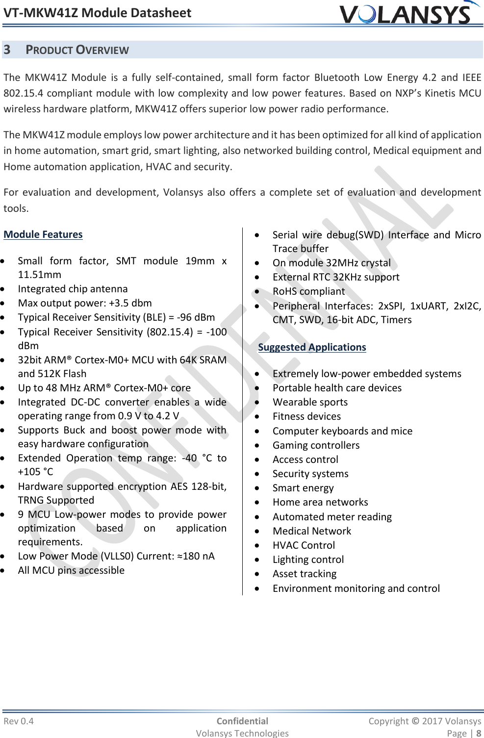
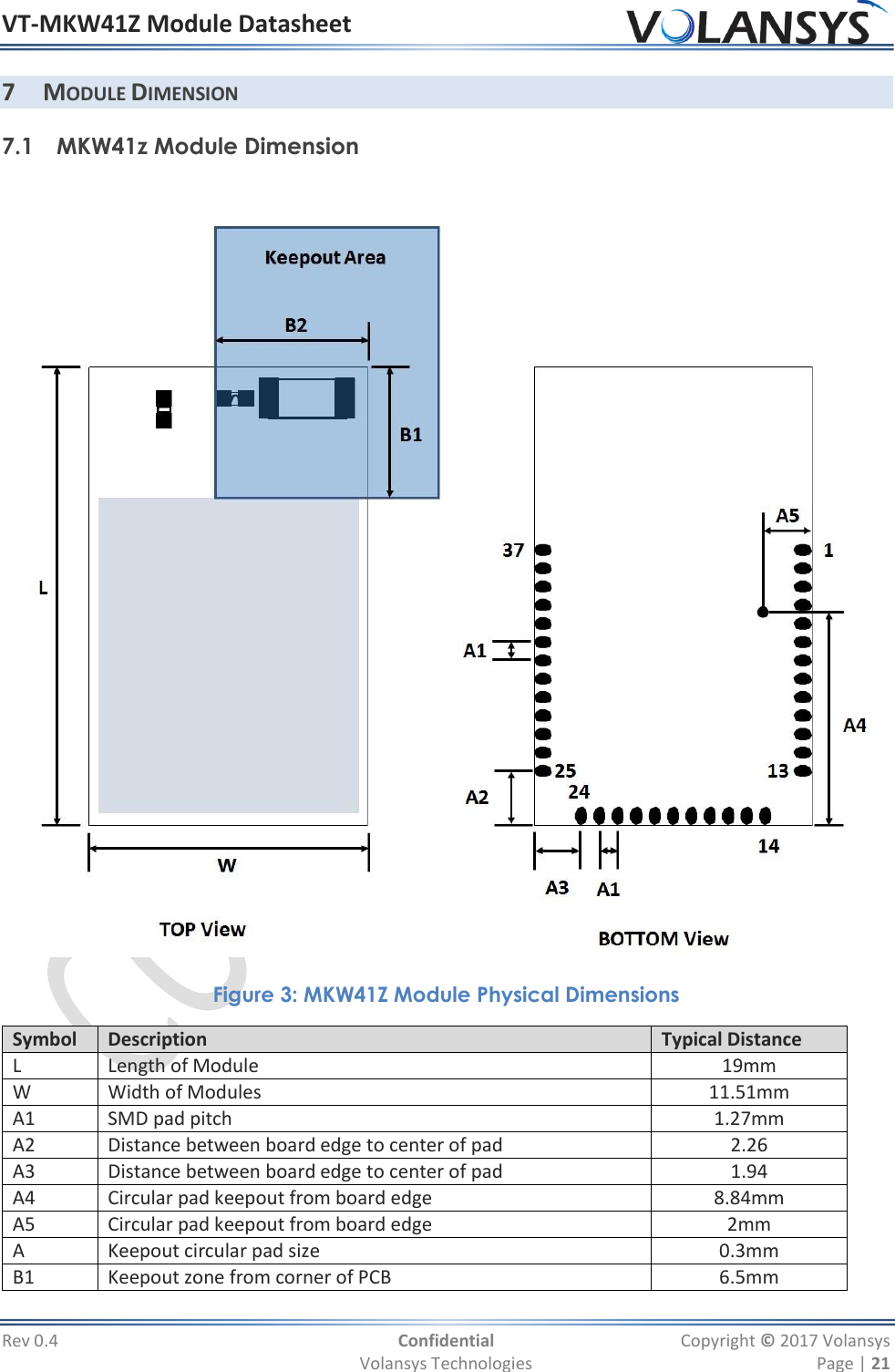
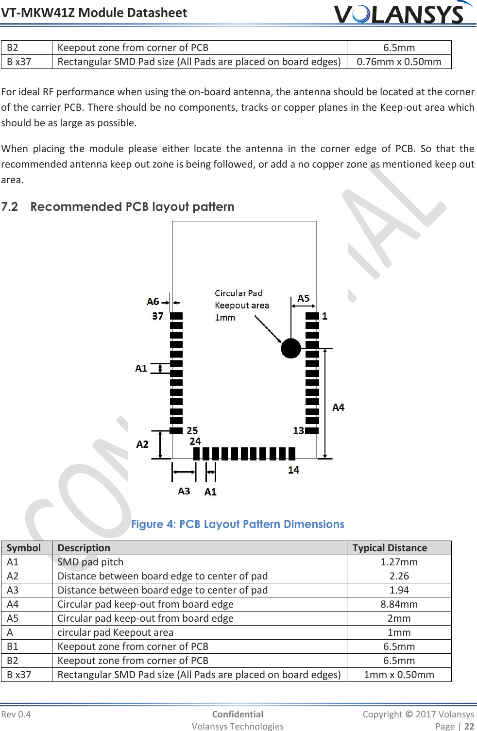
MKW41Z User Manual
Users Manual
Navigation menu
Upload a User Manual
Namespaces
Wiki Guide
HTML
PDF
Info
Views
User Manual
Discussion / Help
Navigation
![VT-MKW41Z Module Datasheet Rev 0.4 Confidential Copyright © 2017 Volansys Volansys Technologies Page | 26 this device does not cause harmful interference. This Class B digital apparatus complies with Canadian ICES‐003 (Cet appareil numérique de la Classe B conforme à la norme NMB‐003 du Canada). This equipment(IC:22256-MKW41Z) complies with IC radiation exposure limits set forth for an uncontrolled environment. This equipment should be installed and operated with minimum distance of 20 cm between the radiator and your body. This transmitter must not be co-located or operating in conjunction with any other antenna or transmitter. Le présent appareil est conforme aux CNR d'Industrie Canada applicables aux appareils radio exempts de licence. L'exploitation est autorisée aux deux conditions suivantes : (1) l'appareil ne doit pas produire de brouillage, et (2) l'utilisateur de l'appareil doit accepter tout brouillage radioélectrique subi, même si le brouillage est susceptible d'en compromettre le fonctionnement. Cet équipement (IC: 22256-MKW41Z) est conforme aux limites IC d'exposition aux radiations définies pour un environnement non contrôlé. Cet équipement doit être installé et utilisé avec une distance minimale de 20 cm entre le radiateur et votre corps. Cet émetteur ne doit pas être situé ou opérant en conjonction avec une autre antenne ou émetteur. 9.5 CE Regulatory Max RF power: BLE(2402-2480MHz): 3.8dBm Thread(2400-2483.5MHz): 3.1dBm RF exposure information: The Maximum Permissible Exposure (MPE) level has been calculated based on a distance of d=20 cm between the device and the human body. To maintain compliance with RF exposure requirement, use product that maintain a 20cm distance between the device and human body. Regulatory Conformance: Hereby, VOLANSYS TECHNOLOGIES PVT. LTD. that the radio equipment type [VT-KW41Z] is in compliance with Directive 2014/53/EU. EU declaration of conformity is available at the following internet address: www.volansys.com Notice: Observe the national local regulations in the location where the device is to be used. This device may be restricted for use in some or all member states of the European Union (EU)](https://usermanual.wiki/Volansys-Technologies-pvt/MKW41Z/User-Guide-3431650-Page-26.png)