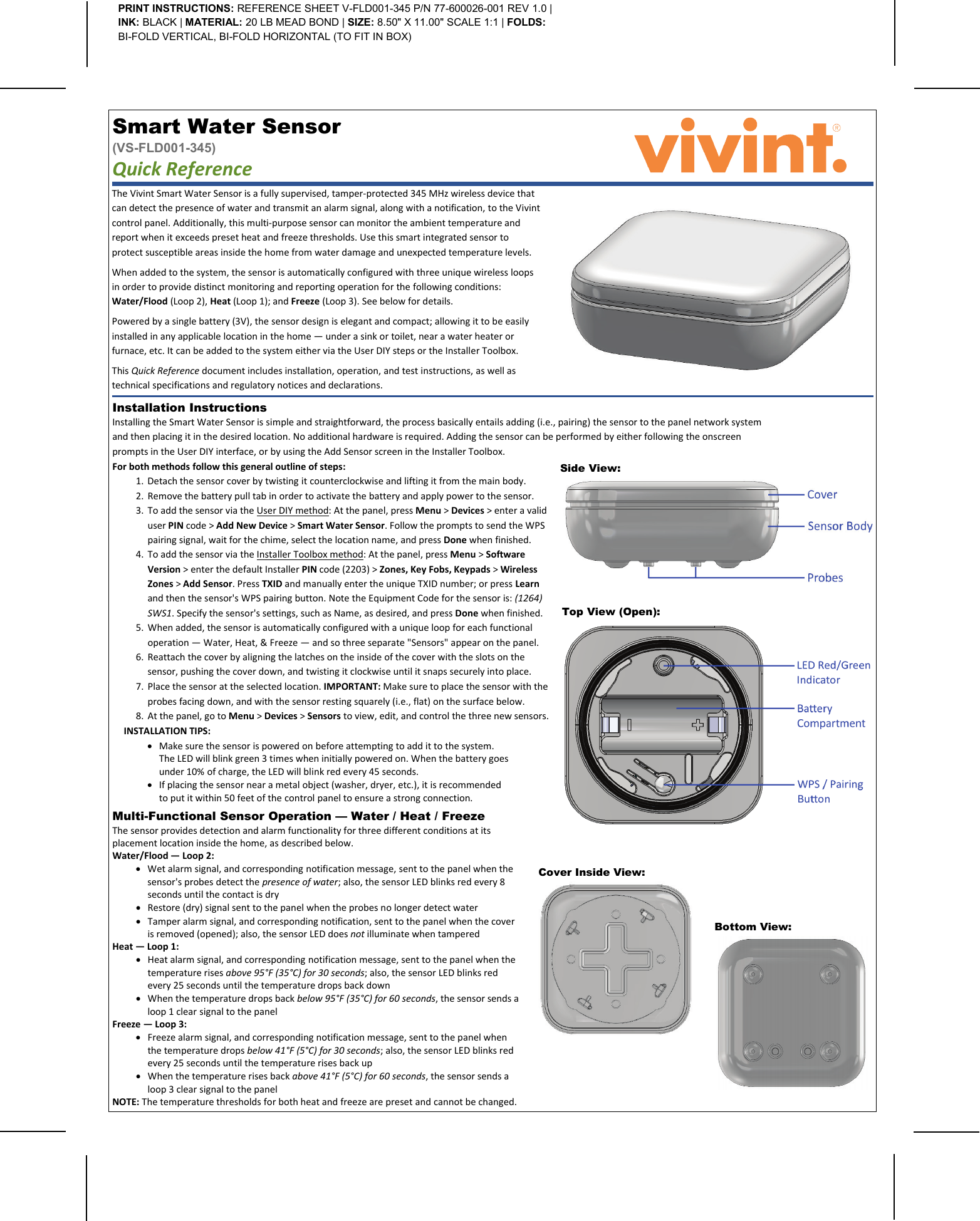
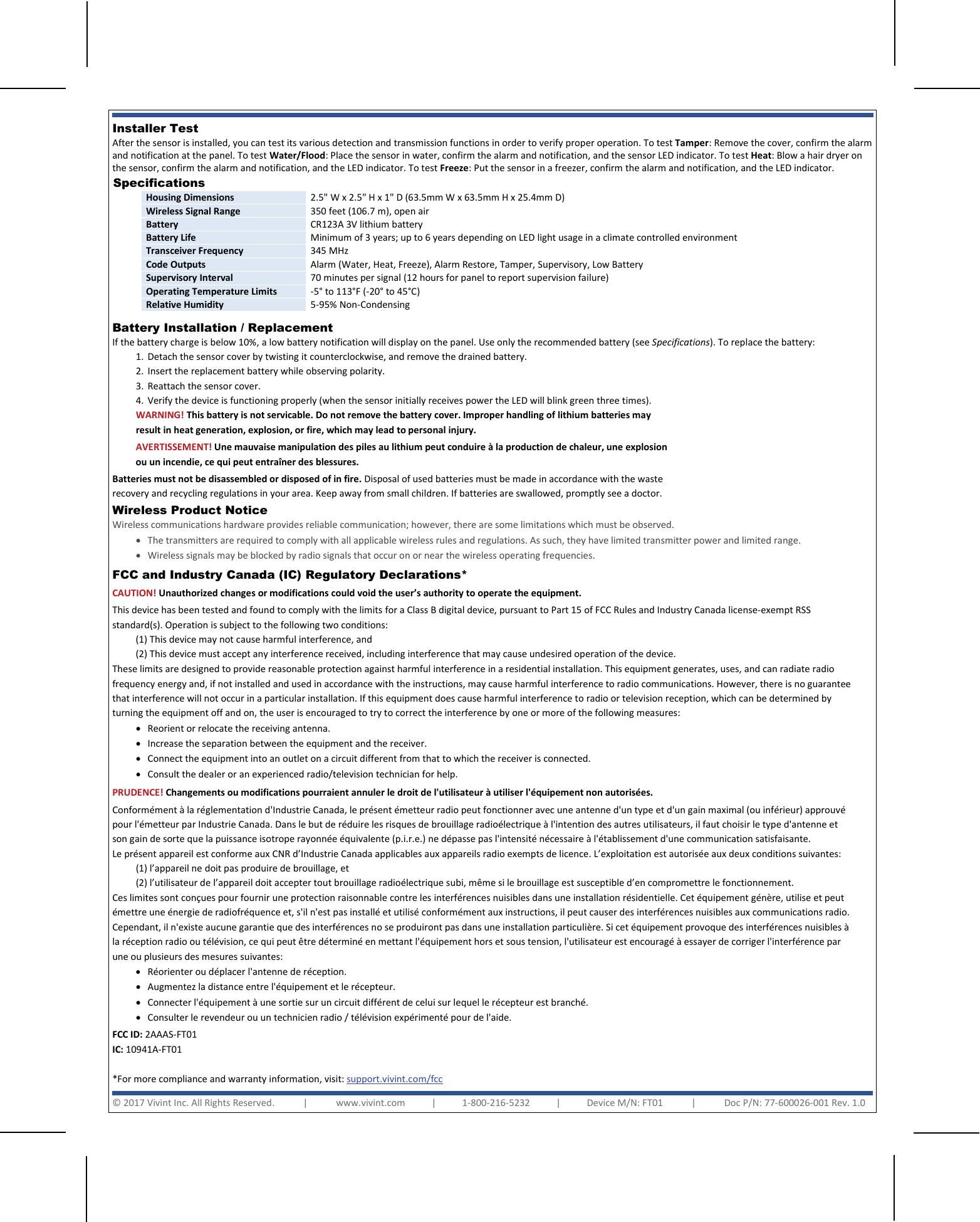
Vivint FT01 Temperature and water sensor User Manual

Vivint. Inc. Temperature and water sensor

User Manual

  Cover Inside View:   Installation Instructions  Installing the Smart Water Sensor is simple and straightforward, the process basically entails adding (i.e., pairing) the sensor to the panel network system and then placing it in the desired location. No additional hardware is required. Adding the sensor can be performed by either following the onscreen prompts in the User DIY interface, or by using the Add Sensor screen in the Installer Toolbox.     The Vivint Smart Water Sensor is a fully supervised, tamper-protected 345 MHz wireless device that can detect the presence of water and transmit an alarm signal, along with a notification, to the Vivint control panel. Additionally, this multi-purpose sensor can monitor the ambient temperature and report when it exceeds preset heat and freeze thresholds. Use this smart integrated sensor to protect susceptible areas inside the home from water damage and unexpected temperature levels. When added to the system, the sensor is automatically configured with three unique wireless loops in order to provide distinct monitoring and reporting operation for the following conditions: Water/Flood (Loop 2), Heat (Loop 1); and Freeze (Loop 3). See below for details. Powered by a single battery (3V), the sensor design is elegant and compact; allowing it to be easily installed in any applicable location in the home — under a sink or toilet, near a water heater or furnace, etc. It can be added to the system either via the User DIY steps or the Installer Toolbox. This Quick Reference document includes installation, operation, and test instructions, as well as technical specifications and regulatory notices and declarations. Smart Water Sensor  (VS-FLD001-345) Quick Reference   PRINT INSTRUCTIONS: REFERENCE SHEET V-FLD001-345 P/N 77-600026-001 REV 1.0 | INK: BLACK | MATERIAL: 20 LB MEAD BOND | SIZE: 8.50" X 11.00" SCALE 1:1 | FOLDS: BI-FOLD VERTICAL, BI-FOLD HORIZONTAL (TO FIT IN BOX) Side View:   For both methods follow this general outline of steps: 1. Detach the sensor cover by twisting it counterclockwise and lifting it from the main body. 2. Remove the battery pull tab in order to activate the battery and apply power to the sensor. 3. To add the sensor via the User DIY method: At the panel, press Menu > Devices > enter a valid user PIN code > Add New Device > Smart Water Sensor. Follow the prompts to send the WPS pairing signal, wait for the chime, select the location name, and press Done when finished. 4. To add the sensor via the Installer Toolbox method: At the panel, press Menu > Software Version > enter the default Installer PIN code (2203) > Zones, Key Fobs, Keypads > Wireless Zones > Add Sensor. Press TXID and manually enter the unique TXID number; or press Learn and then the sensor's WPS pairing button. Note the Equipment Code for the sensor is: (1264) SWS1. Specify the sensor's settings, such as Name, as desired, and press Done when finished. 5. When added, the sensor is automatically configured with a unique loop for each functional operation — Water, Heat, & Freeze — and so three separate "Sensors" appear on the panel. 6. Reattach the cover by aligning the latches on the inside of the cover with the slots on the sensor, pushing the cover down, and twisting it clockwise until it snaps securely into place. 7. Place the sensor at the selected location. IMPORTANT: Make sure to place the sensor with the probes facing down, and with the sensor resting squarely (i.e., flat) on the surface below. 8. At the panel, go to Menu > Devices > Sensors to view, edit, and control the three new sensors. INSTALLATION TIPS: • Make sure the sensor is powered on before attempting to add it to the system. The LED will blink green 3 times when initially powered on. When the battery goes under 10% of charge, the LED will blink red every 45 seconds. • If placing the sensor near a metal object (washer, dryer, etc.), it is recommended to put it within 50 feet of the control panel to ensure a strong connection.  Top View (Open):   Bottom View:   Multi-Functional Sensor Operation — Water / Heat / Freeze  The sensor provides detection and alarm functionality for three different conditions at its placement location inside the home, as described below. Water/Flood — Loop 2: • Wet alarm signal, and corresponding notification message, sent to the panel when the sensor's probes detect the presence of water; also, the sensor LED blinks red every 8 seconds until the contact is dry • Restore (dry) signal sent to the panel when the probes no longer detect water • Tamper alarm signal, and corresponding notification, sent to the panel when the cover is removed (opened); also, the sensor LED does not illuminate when tampered Heat — Loop 1: • Heat alarm signal, and corresponding notification message, sent to the panel when the temperature rises above 95°F (35°C) for 30 seconds; also, the sensor LED blinks red every 25 seconds until the temperature drops back down • When the temperature drops back below 95°F (35°C) for 60 seconds, the sensor sends a loop 1 clear signal to the panel Freeze — Loop 3: • Freeze alarm signal, and corresponding notification message, sent to the panel when the temperature drops below 41°F (5°C) for 30 seconds; also, the sensor LED blinks red every 25 seconds until the temperature rises back up • When the temperature rises back above 41°F (5°C) for 60 seconds, the sensor sends a loop 3 clear signal to the panel NOTE: The temperature thresholds for both heat and freeze are preset and cannot be changed.
   Installer Test  After the sensor is installed, you can test its various detection and transmission functions in order to verify proper operation. To test Tamper: Remove the cover, confirm the alarm and notification at the panel. To test Water/Flood: Place the sensor in water, confirm the alarm and notification, and the sensor LED indicator. To test Heat: Blow a hair dryer on the sensor, confirm the alarm and notification, and the LED indicator. To test Freeze: Put the sensor in a freezer, confirm the alarm and notification, and the LED indicator. Specifications  Housing Dimensions 2.5" W x 2.5" H x 1" D (63.5mm W x 63.5mm H x 25.4mm D) Wireless Signal Range 350 feet (106.7 m), open air Battery CR123A 3V lithium battery Battery Life Minimum of 3 years; up to 6 years depending on LED light usage in a climate controlled environment Transceiver Frequency 345 MHz Code Outputs Alarm (Water, Heat, Freeze), Alarm Restore, Tamper, Supervisory, Low Battery  Supervisory Interval 70 minutes per signal (12 hours for panel to report supervision failure) Operating Temperature Limits -5° to 113°F (-20° to 45°C) Relative Humidity 5-95% Non-Condensing  Battery Installation / Replacement If the battery charge is below 10%, a low battery notification will display on the panel. Use only the recommended battery (see Specifications). To replace the battery: 1. Detach the sensor cover by twisting it counterclockwise, and remove the drained battery. 2. Insert the replacement battery while observing polarity. 3. Reattach the sensor cover. 4. Verify the device is functioning properly (when the sensor initially receives power the LED will blink green three times). FCC and Industry Canada (IC) Regulatory Declarations*  CAUTION! Unauthorized changes or modifications could void the user’s authority to operate the equipment. This device has been tested and found to comply with the limits for a Class B digital device, pursuant to Part 15 of FCC Rules and Industry Canada license-exempt RSS standard(s). Operation is subject to the following two conditions: (1) This device may not cause harmful interference, and (2) This device must accept any interference received, including interference that may cause undesired operation of the device. These limits are designed to provide reasonable protection against harmful interference in a residential installation. This equipment generates, uses, and can radiate radio frequency energy and, if not installed and used in accordance with the instructions, may cause harmful interference to radio communications. However, there is no guarantee that interference will not occur in a particular installation. If this equipment does cause harmful interference to radio or television reception, which can be determined by turning the equipment off and on, the user is encouraged to try to correct the interference by one or more of the following measures:  • Reorient or relocate the receiving antenna.  • Increase the separation between the equipment and the receiver.  • Connect the equipment into an outlet on a circuit different from that to which the receiver is connected.  • Consult the dealer or an experienced radio/television technician for help. PRUDENCE! Changements ou modifications pourraient annuler le droit de l'utilisateur à utiliser l'équipement non autorisées. Conformément à la réglementation d'Industrie Canada, le présent émetteur radio peut fonctionner avec une antenne d'un type et d'un gain maximal (ou inférieur) approuvé pour l'émetteur par Industrie Canada. Dans le but de réduire les risques de brouillage radioélectrique à l'intention des autres utilisateurs, il faut choisir le type d'antenne et son gain de sorte que la puissance isotrope rayonnée équivalente (p.i.r.e.) ne dépasse pas l'intensité nécessaire à l'établissement d'une communication satisfaisante. Le présent appareil est conforme aux CNR d’Industrie Canada applicables aux appareils radio exempts de licence. L’exploitation est autorisée aux deux conditions suivantes: (1) l’appareil ne doit pas produire de brouillage, et  (2) l’utilisateur de l’appareil doit accepter tout brouillage radioélectrique subi, même si le brouillage est susceptible d’en compromettre le fonctionnement. Ces limites sont conçues pour fournir une protection raisonnable contre les interférences nuisibles dans une installation résidentielle. Cet équipement génère, utilise et peut émettre une énergie de radiofréquence et, s'il n'est pas installé et utilisé conformément aux instructions, il peut causer des interférences nuisibles aux communications radio. Cependant, il n'existe aucune garantie que des interférences no se produiront pas dans une installation particulière. Si cet équipement provoque des interférences nuisibles à la réception radio ou télévision, ce qui peut être déterminé en mettant l'équipement hors et sous tension, l'utilisateur est encouragé à essayer de corriger l'interférence par une ou plusieurs des mesures suivantes:  • Réorienter ou déplacer l'antenne de réception.  • Augmentez la distance entre l'équipement et le récepteur.  • Connecter l'équipement à une sortie sur un circuit différent de celui sur lequel le récepteur est branché. • Consulter le revendeur ou un technicien radio / télévision expérimenté pour de l'aide. FCC ID: 2AAAS-FT01  IC: 10941A-FT01  *For more compliance and warranty information, visit: support.vivint.com/fcc WARNING! This battery is not servicable. Do not remove the battery cover. Improper handling of lithium batteries may result in heat generation, explosion, or fire, which may lead to personal injury. AVERTISSEMENT! Une mauvaise manipulation des piles au lithium peut conduire à la production de chaleur, une explosion ou un incendie, ce qui peut entraîner des blessures. Batteries must not be disassembled or disposed of in fire. Disposal of used batteries must be made in accordance with the waste recovery and recycling regulations in your area. Keep away from small children. If batteries are swallowed, promptly see a doctor. © 2017 Vivint Inc. All Rights Reserved.            |            www.vivint.com           |           1-800-216-5232           |           Device M/N: FT01            |            Doc P/N: 77-600026-001 Rev. 1.0  Wireless Product Notice  Wireless communications hardware provides reliable communication; however, there are some limitations which must be observed. • The transmitters are required to comply with all applicable wireless rules and regulations. As such, they have limited transmitter power and limited range. • Wireless signals may be blocked by radio signals that occur on or near the wireless operating frequencies.

Navigation menu