Vivint DW01 Security Signaling Equipment User Manual
Vivint. Inc. Security Signaling Equipment Users Manual
UserManual.wiki
>
Vivint
>
DW01 User Manual
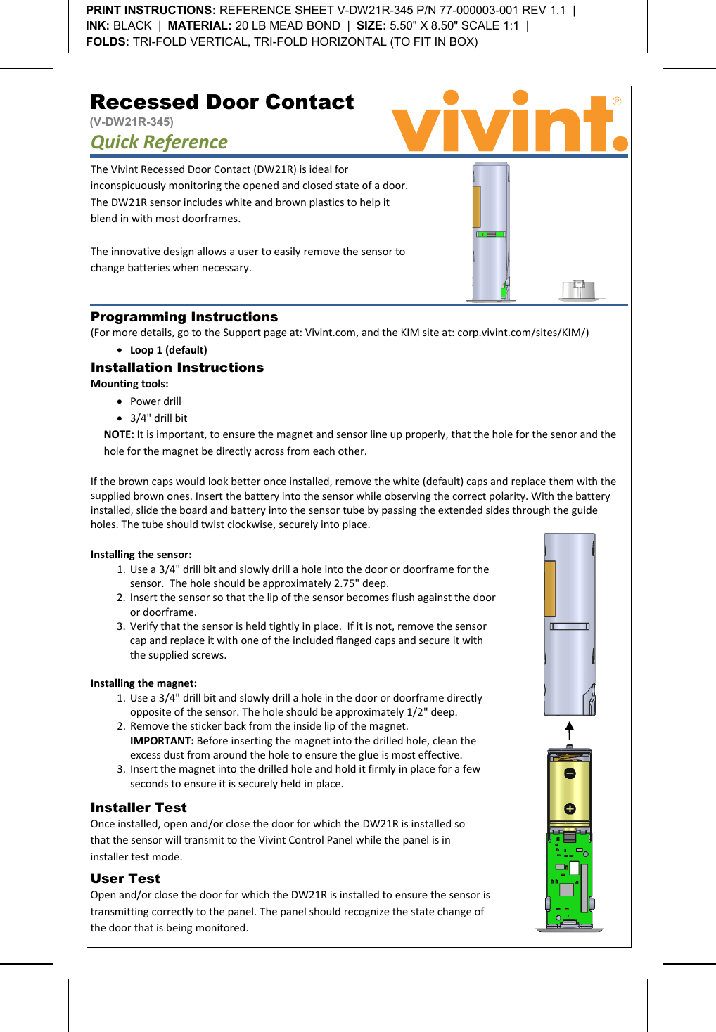
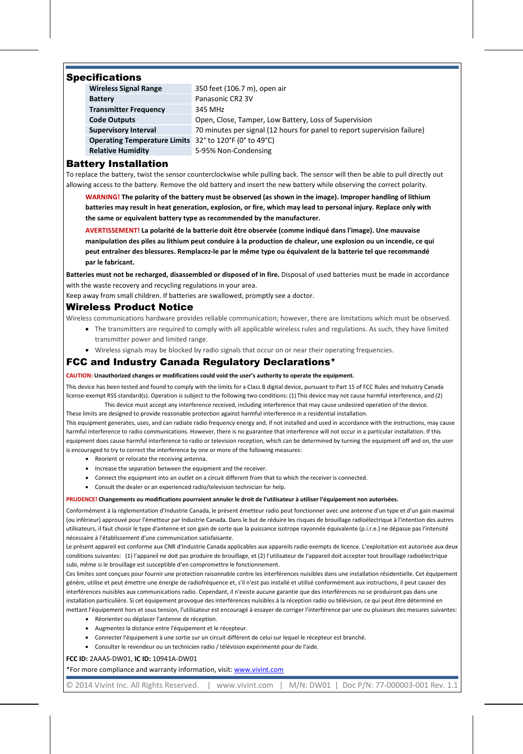
Users Manual
Navigation menu
Upload a User Manual
Namespaces
Wiki Guide
HTML
PDF
Info
Views
User Manual
Discussion / Help
Navigation