Visionary RDX RADIATION DETECTION DEVICE User Manual V019231 05AD Rad DX Manualx
Visionary Products, Inc. RADIATION DETECTION DEVICE V019231 05AD Rad DX Manualx
UserManual.wiki
>
Visionary
>
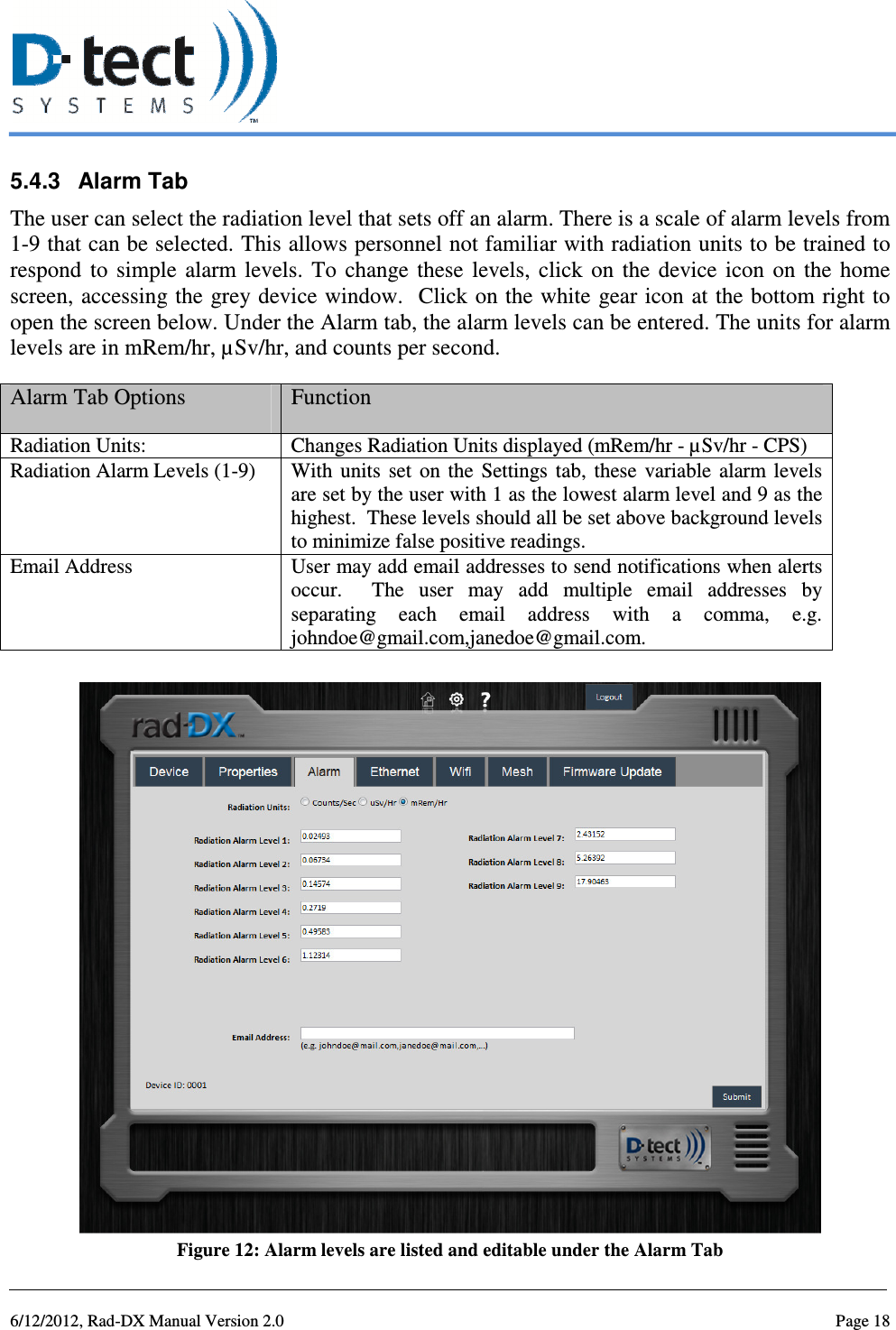
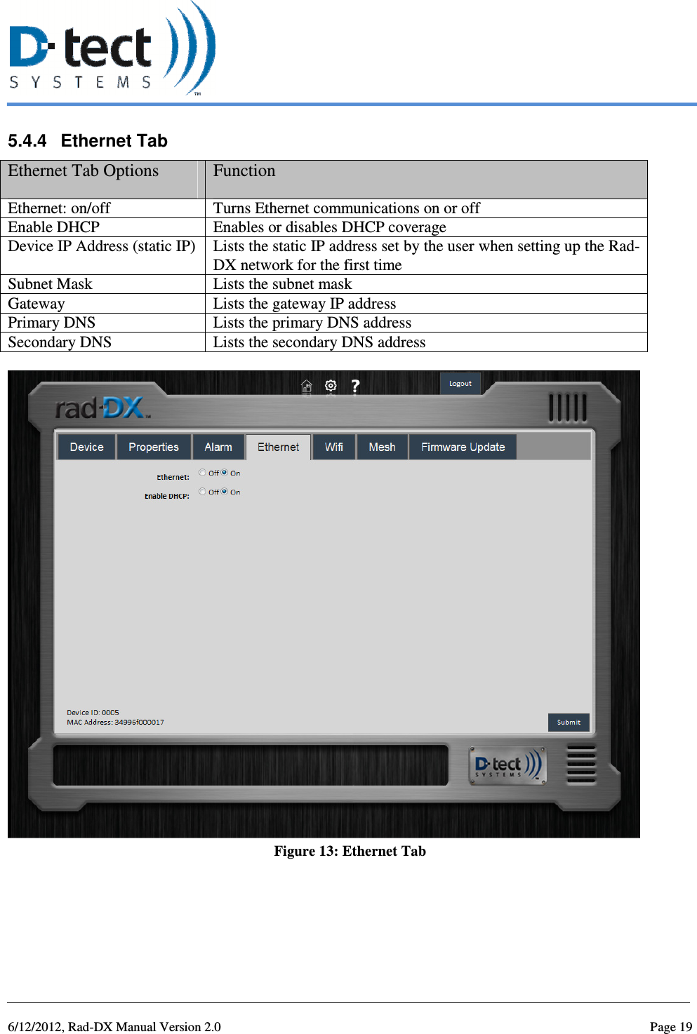
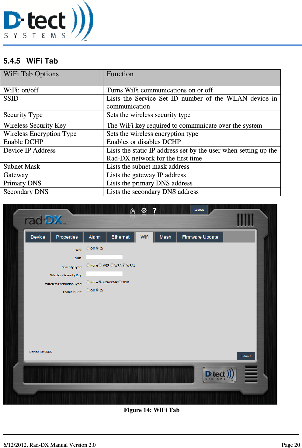
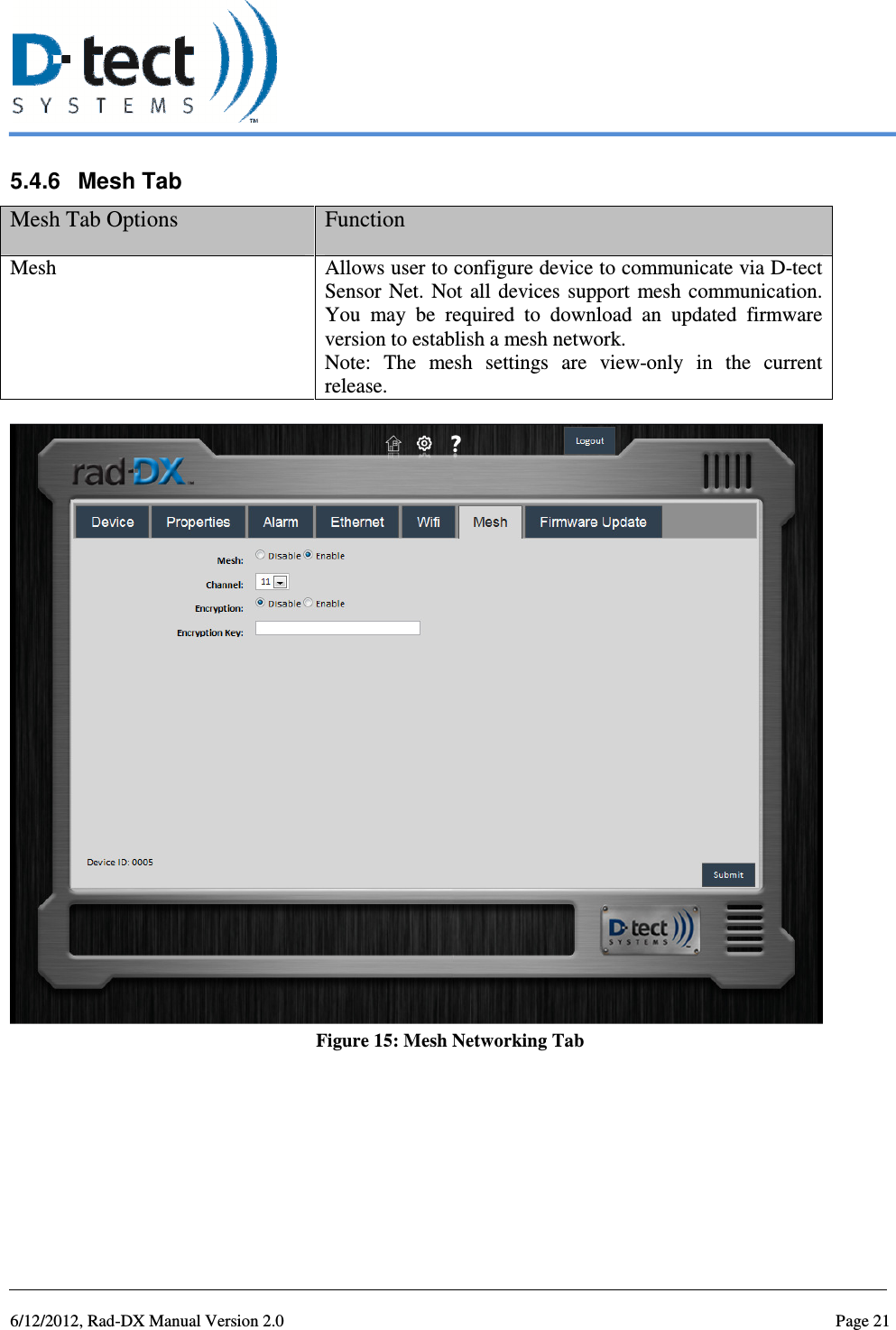
RDX User Manual
Users Manual
Navigation menu
Upload a User Manual
Namespaces
Wiki Guide
HTML
PDF
Info
Views
User Manual
Discussion / Help
Navigation