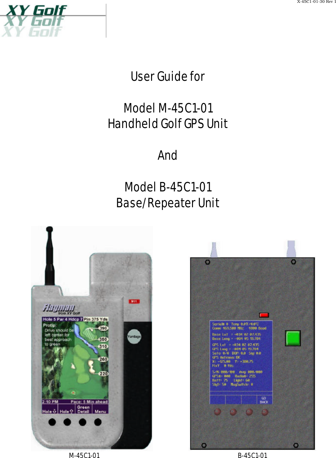
VXT M-45C1-01 Hand Held Radio User Manual

VXT, L.L.C. Hand Held Radio Users Manual

Users Manual

X-45C1-01-30 Rev 1       User Guide for  Model M-45C1-01  Handheld Golf GPS Unit  And  Model B-45C1-01  Base/Repeater Unit        M-45C1-01 B-45C1-01
X-45C1-01-30 Rev 1     1I.  Introduction  This guide covers operation of XY Golf’s Handheld Golf GPS unit and Base/Repeater Unit. The operation of either unit is very similar. Specific functionality of the units is defined by software, which utilizes a standard soft-key menu system to access various parameters and functions.  NOTE: "THIS EQUIPMENT COMPLIES WITH PART 90 OF THE FCC RULES. ANY CHANGES OR MODIFICATIONS NOT EXPRESSLY APPROVED BY THE MANUFACTURER COULD VOID THE USER'S AUTHORITY TO OPERATE THE EQUIPMENT."   II. Usage  The M-45C-01, Hand Held Unit (HHU) is designed to be used by a golfer. It relies on GPS and predefined data to provided assistance to the golfer in the form of distance data, shot advice, and other information.  During usage the unit ordinarily resides in a cradle attached to a golf cart or golf bag. The golfer will typically pick up hold the unit and refer to it before making each shot and then place it back in the cradle.   The B-45C-01, Base/Repeater Unit (BSU), is designed to operate as a fixed unit in either of two modes. In Base Mode, it serves as the communication controller for all HHUs and Repeaters within a specific area (typically a single golf course). It also provides Differential GPS (DGPS) correction data to HHUs to enhance their positional accuracy.   In Repeater Mode, the B-45C-01 is used to extend the radio coverage of the BSU. This may be needed if the size of a particular installation is unusually large, or there are obstacles like hills or large buildings blocking radio coverage to specific areas.   A typical Base/Repeater installation utilizes an outdoor fix-mounted antenna no higher than 30 feet above ground level. Appropriate FCC Licensing or Authorization is required prior to station operation.  III. Operation  This section describes the operation of the units. Since the many options are enabled or disabled via a separate database, the actual menu options available may be slightly different than those shown here. This document will show all options that are currently available.
X-45C1-01-30 Rev 1     2A. Main Menu  When the unit is initially powered up or reset the main menu will appear as shown in Figure 1. The actual screen may appear differently than the one shown here, or may not appear at all, depending on options set in the unit initialization database.    Figure 1. Main Menu  1)  Play Course 2)  Settings 3)  System Menu 4)  FCC Menu
X-45C1-01-30 Rev 1     3 I.  FCC Menu The FCC Menu contains all of the controls required for Part 15 and Part 90 FCC testing.  This screen is only accessible in special in-house firmware builds and is not available to the end user. The FCC Menu is shown below.     Figure 9. FCC Menu  Five Modes are available here: Receive, CW, Continuous Data, Radio Off, and Normal Operation. Additionally, the operator may set the frequency of the radio to one of three points: The lower and upper band limits of the radio, and the center of the band.  A mode may be activated by highlighting it using the Down/Up soft-keys, then pressing the Enter soft key. The mode may be deactivated by pressing the Enter soft key again.   NOTE: A status line near the bottom of the display will show the current mode of operation.  1)  Radio Receive Activating this function will place the Transceiver in Receive mode at the currently selected frequency.
X-45C1-01-30 Rev 1     42)  Radio CW Activating this mode will cause the transceiver to key-up. No data will be applied to modulate the signal. This function will time out after approximately 3 minutes to protect the transceiver. The unit will revert to Receive Mode after the time-out.  CAUTION: The transceiver is designed to operate at a maximum 50% Transmit/Receive duty cycle. Overheating and equipment failure may occur if the Radio CW mode is repeatedly activated.   3)  Transmit Data Activating the Transmit Data mode will cause the unit to continuously transmit an ASCII data pattern. This function will time out after approximately 3 minutes to protect the transceiver. The unit will revert to Receive Mode after the time-out.  CAUTION: The transceiver is designed to operate at a maximum 50% Transmit/Receive duty cycle. Overheating and equipment failure may occur if the Transmit Data mode is repeatedly activated.   4)  Radio Off This mode will shut off the power supplies to both the Transmitter and Receiver sections of the transceiver.    5)  Normal Operation Normal Operation Mode will cause the unit to behave as it normally does during operation. This involves transmitting an approximately 90-byte message at regular intervals, then reverting back to receive. The message intervals are as follows:   Model Application  Typical Message Interval     M-45C1-01 Handheld Golfer Unit twice per minute     B-45C1-01 Base/Repeater Unit once per second
X-45C1-01-30 Rev 1     56)  Set Frequency This feature allows the user to set the transceiver frequency to any of three points. The unit will initially be set to the center of the radio band (Mid Freq.) upon power-up. The current frequency will be displayed on a status line near the bottom of the display whenever this item is selected. Pressing the Enter soft key causes the frequency to switch to the next frequency. The Set Frequency function may be used while the unit is in any of the above modes (Receive, Transmit, Normal, etc.).   J. Radio Menu  The Radio Menu contains all of the software-adjustable parameters related to the data radio and radio communication. This screen is only accessible in special in-house firmware builds and is not available to the end user. The Radio Menu is shown in Figure 10 below.     Figure 10. Radio Menu  1)  Adjust Pot This adjustment controls the DC bias that is applied to receive data signal (from the transceiver) before it enters the threshold detector. Typical adjustment procedures involve injecting a very low-level, modulated signal into the receiver and adjusting this control for minimum bit error rate.  2)  Adjust Flatness This function may be used to adjust modulation flatness. This alignment is typically performed by monitoring the modulated signal on spectrum analyzer
X-45C1-01-30 Rev 1     6and adjusting this parameter for optimum spectral symmetry. Please refer to the transceiver technical manual for further information.  3)  Adjust TX D/A This adjustment may be used to fine-tune the transmit frequency. Typically, this alignment is accomplished by placing the unit in CW Mode and monitoring the signal with a frequency counter to ensure that the transmitter is correctly tuned. Please refer to the transceiver technical manual for further information.   4)  RX/CW/Data/Off This feature may be used to switch transceiver though various operational modes.   CAUTION: The transceiver is designed to operate at a maximum 50% Transmit/Receive duty cycle. Overheating and equipment failure may occur if the CW or Data modes are left on for extended periods of time.   5)  Change Frequency This function allows the operator to set the current transmit/receive frequency. The frequency will adjust in steps of 50 kHz to 500 kHz depending on the unit configuration database settings.  6)  Change Baud This feature allows the operator to toggle between 4800 and 9600 Baud.

Navigation menu