VTech Telecommunications 80-7597-01 WiFi Gateway User Manual 2
VTech Telecommunications Ltd WiFi Gateway 2
UserManual.wiki
>
VTech Telecommunications
>
80-7597-01 User Manual
>
User Manual 2
Contents
1.
User Manual 1
2.
User Manual 2
3.
User Manual 3
User Manual 2
Navigation menu
Upload a User Manual
Namespaces
Wiki Guide
HTML
PDF
Info
Views
User Manual
Discussion / Help
Navigation
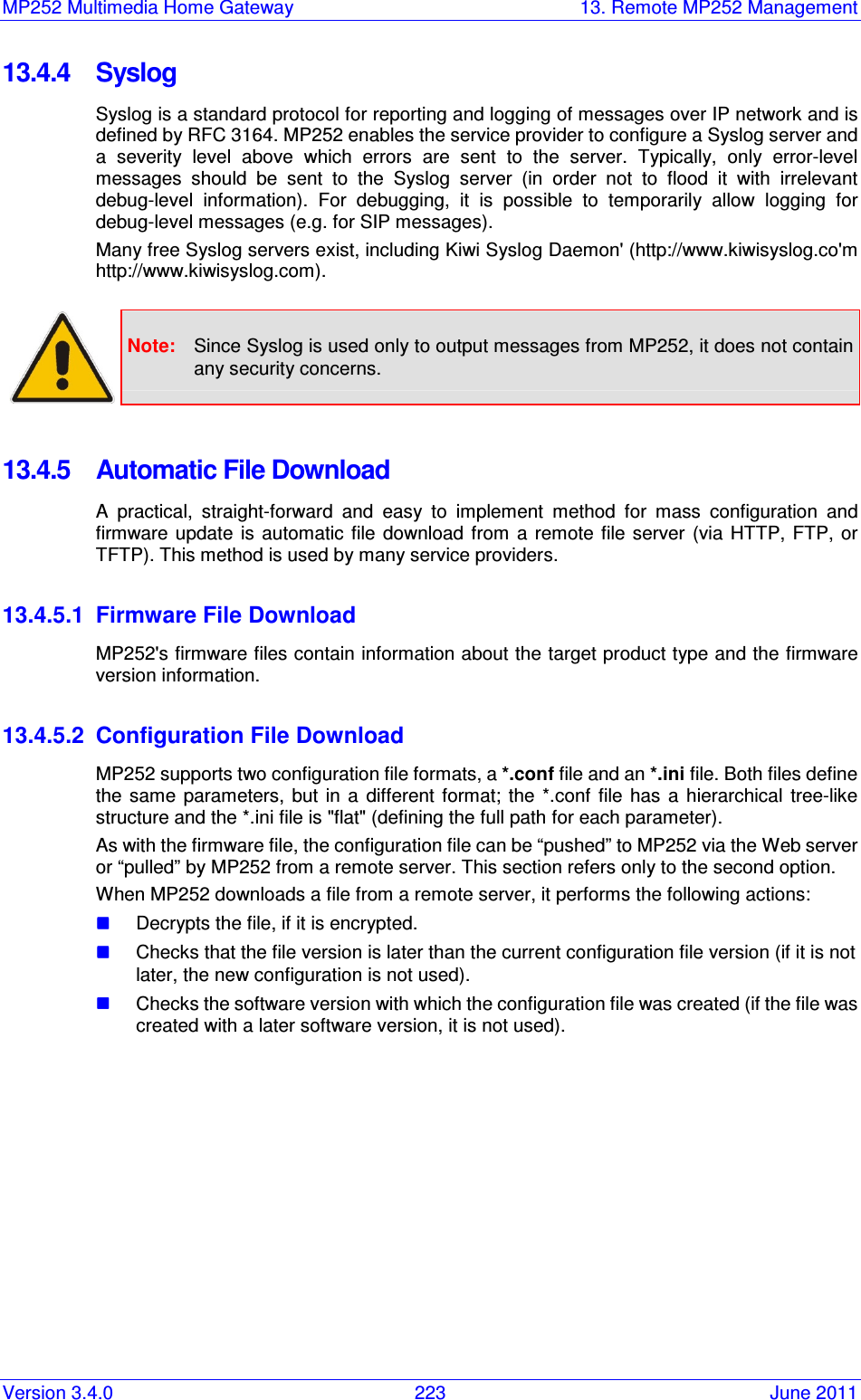
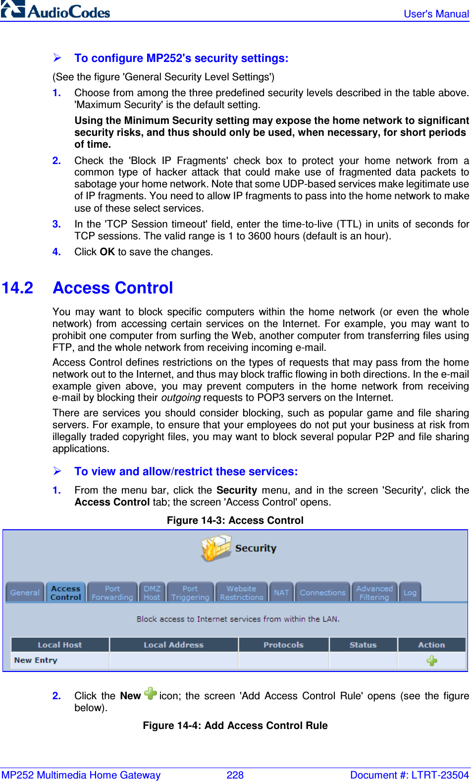
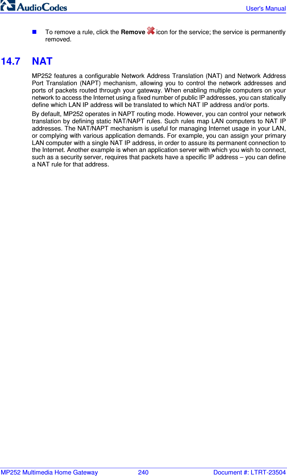
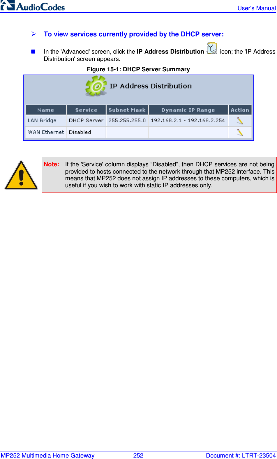
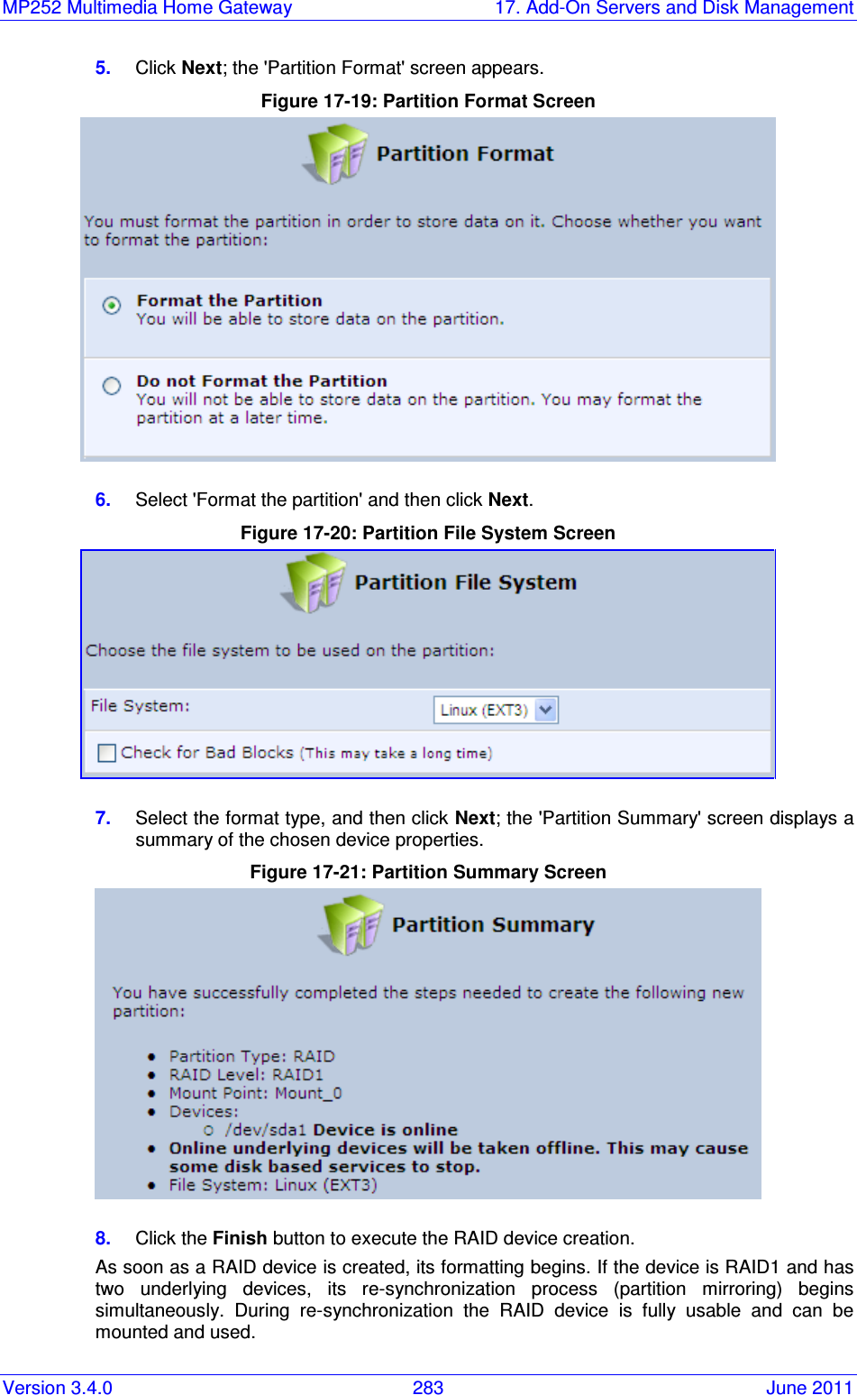
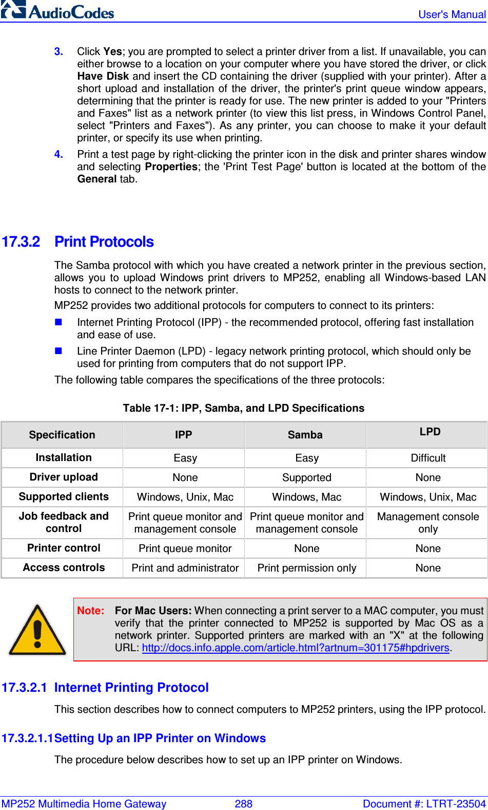

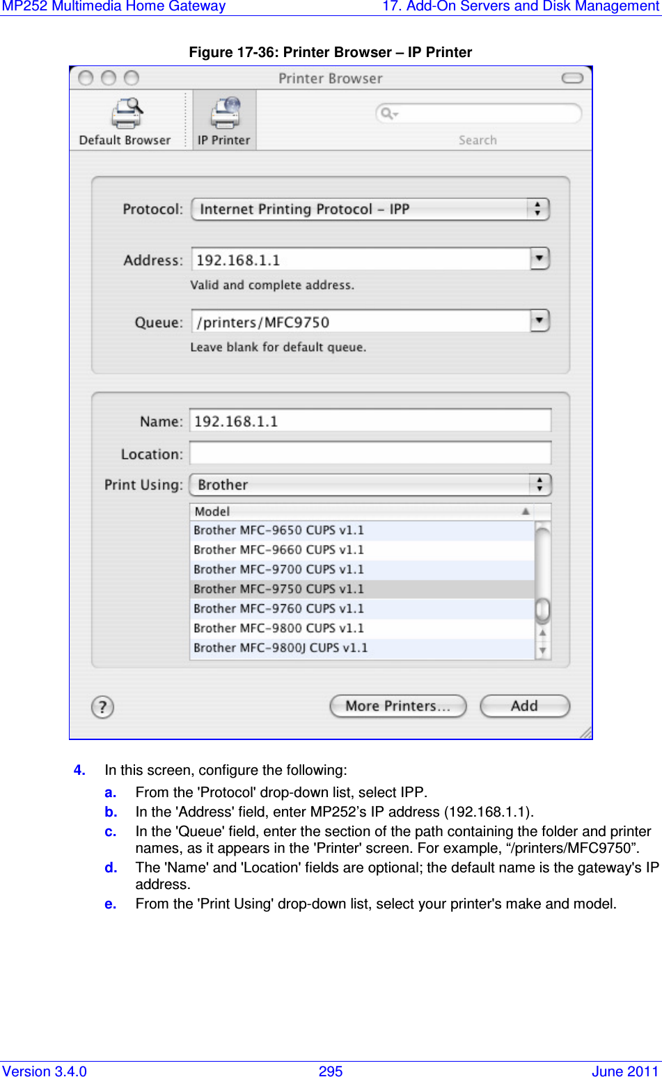
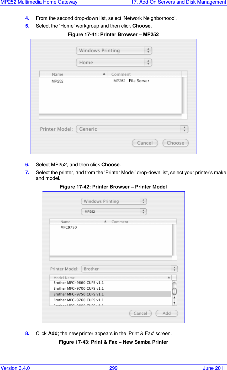
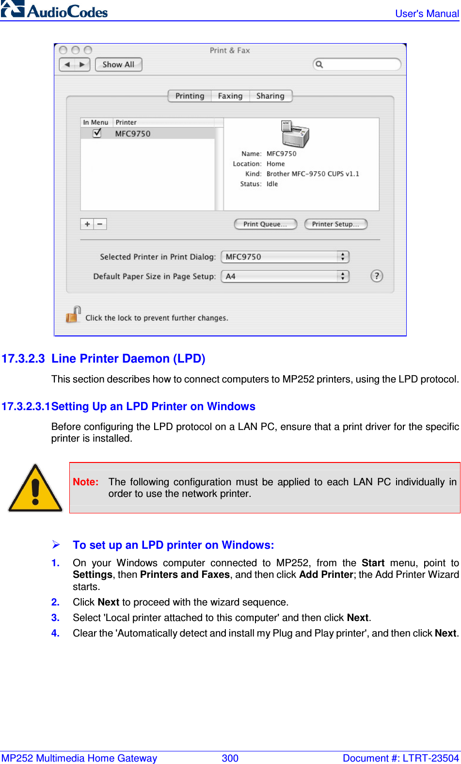
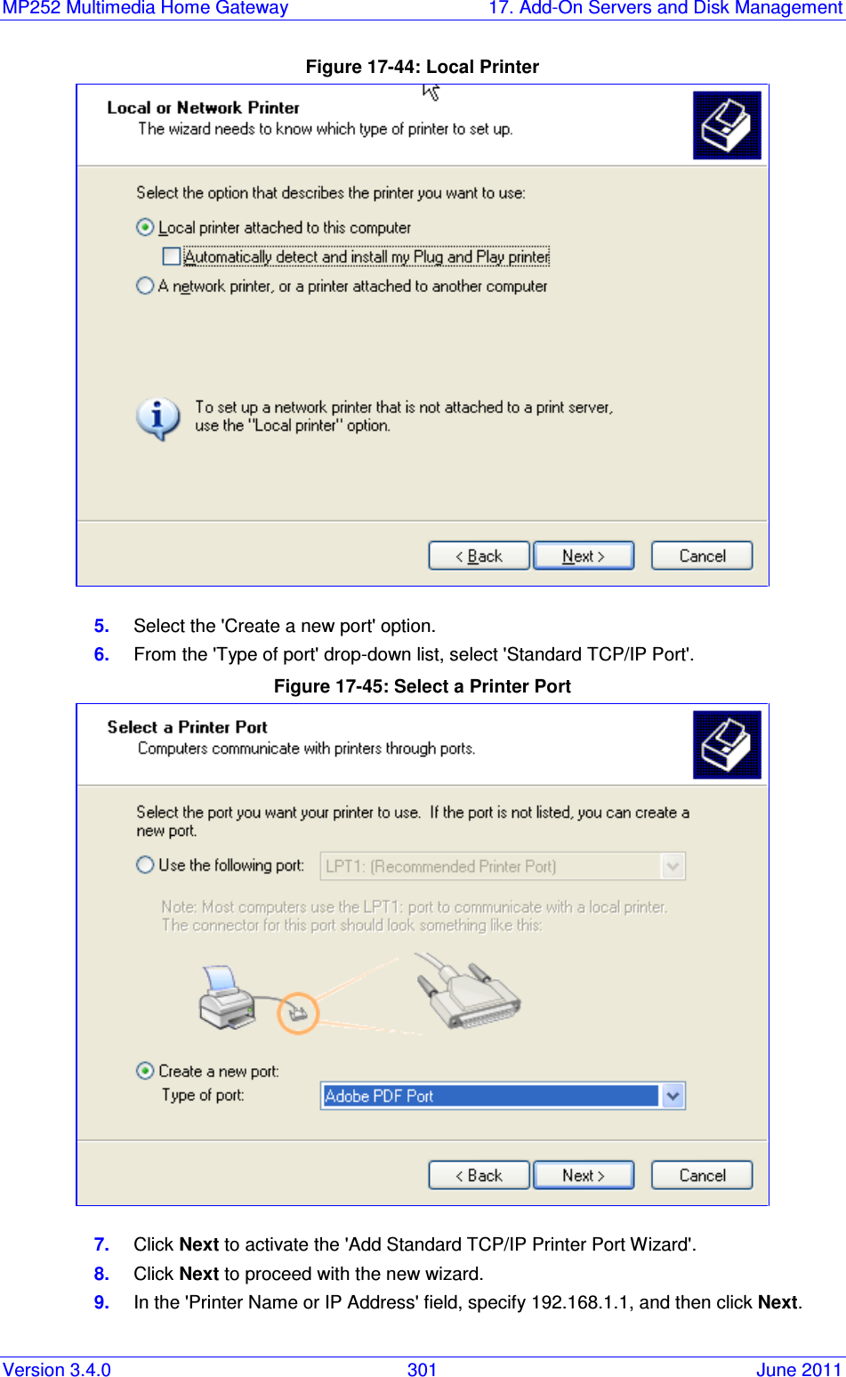
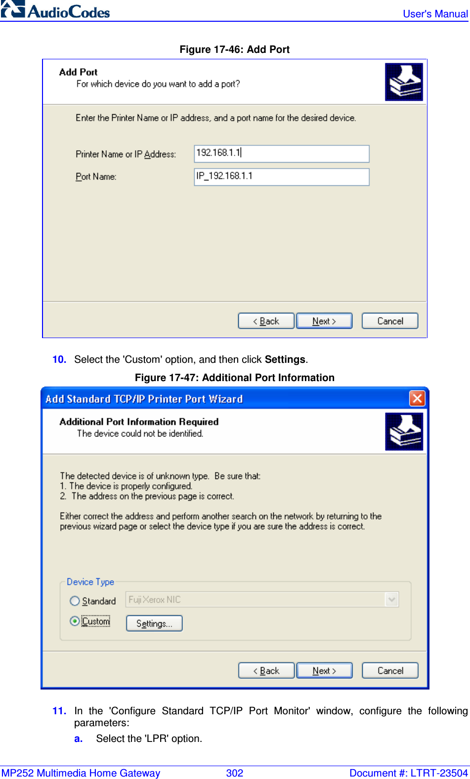
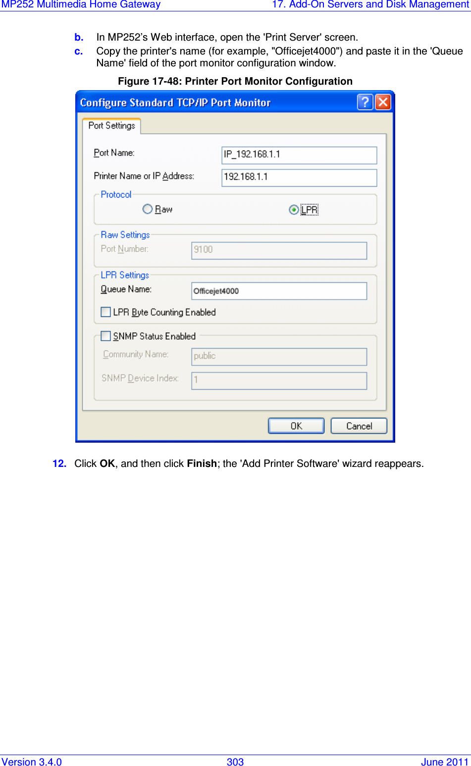
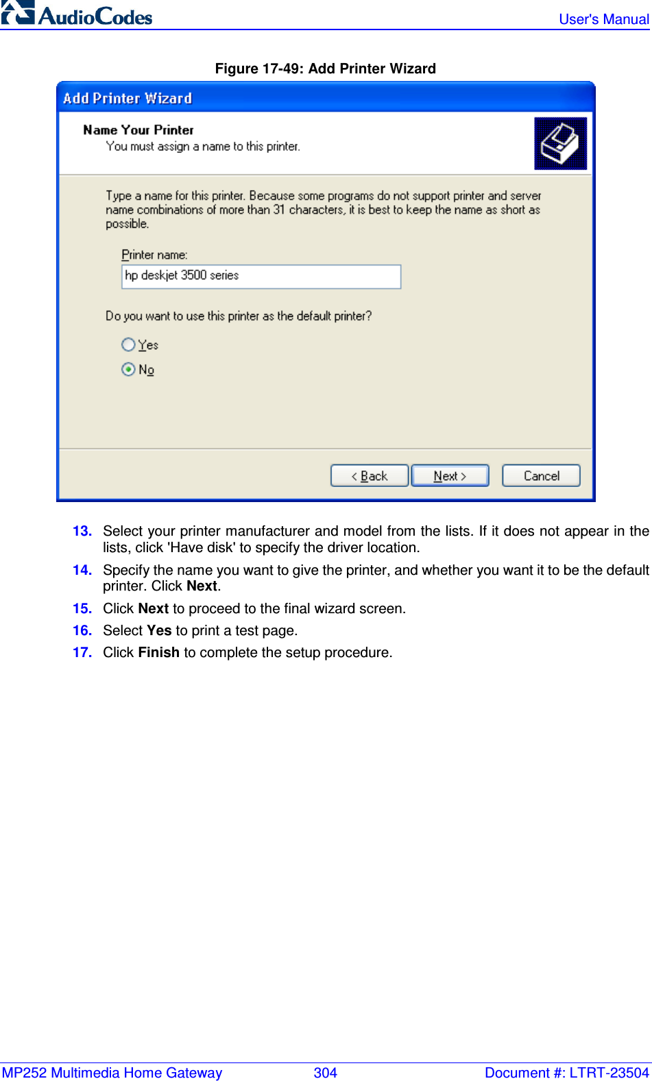
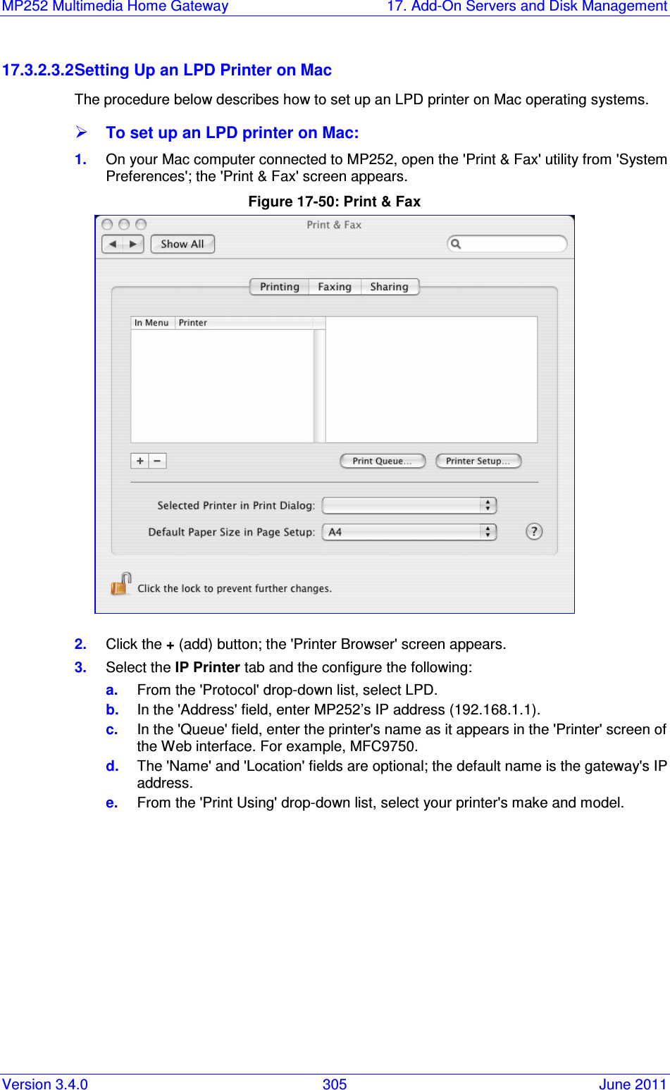
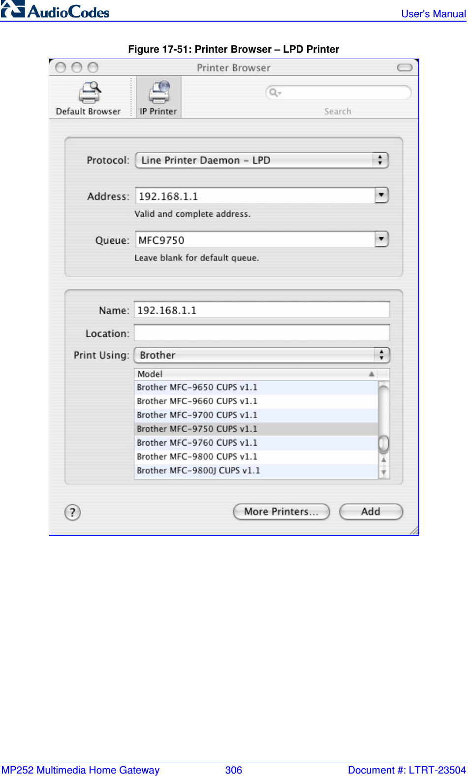
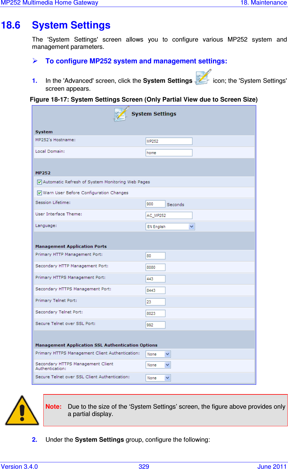
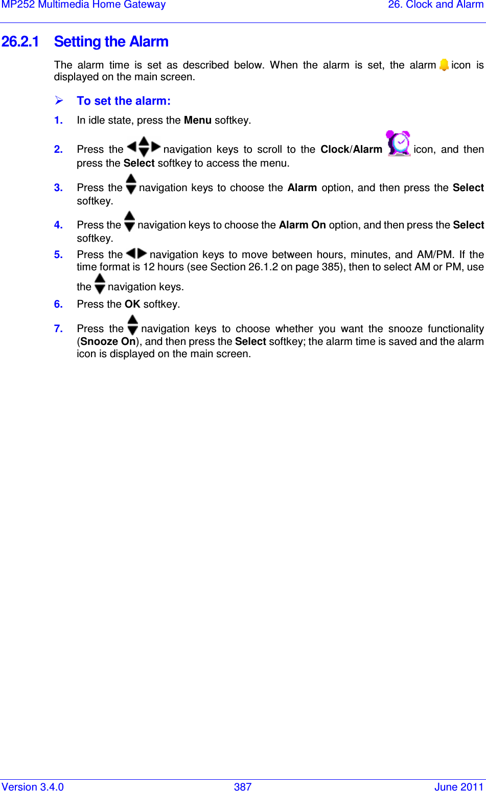
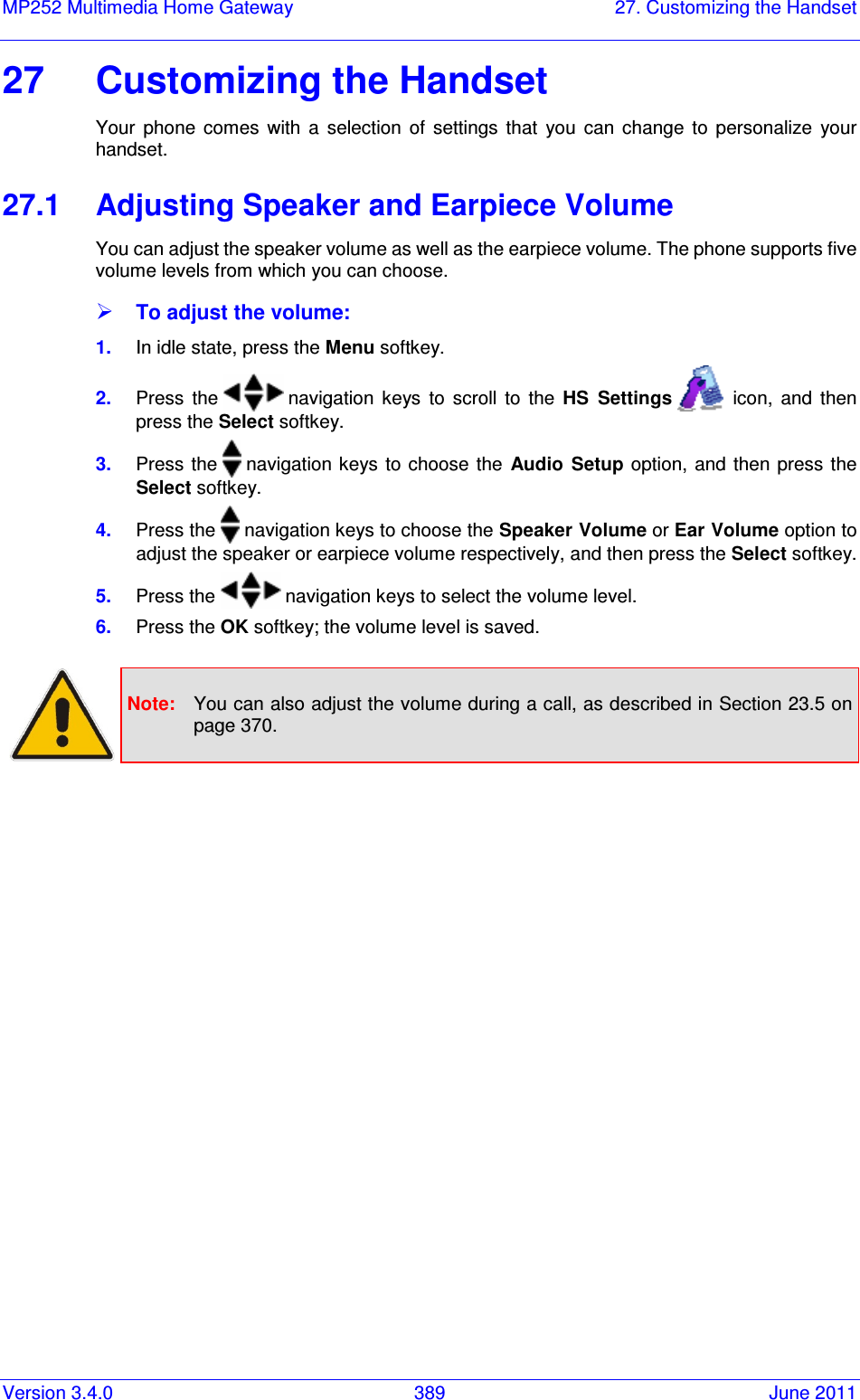
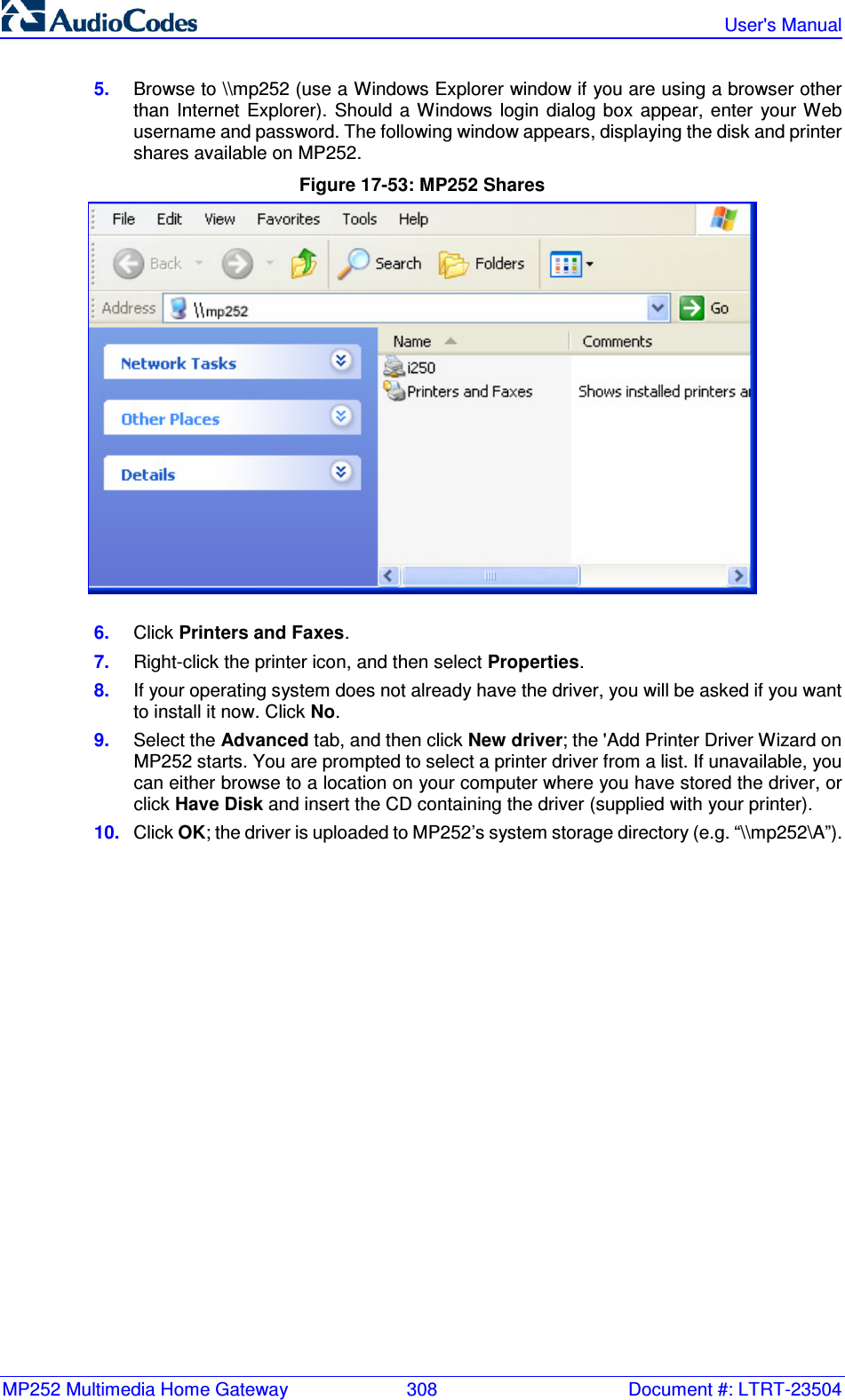
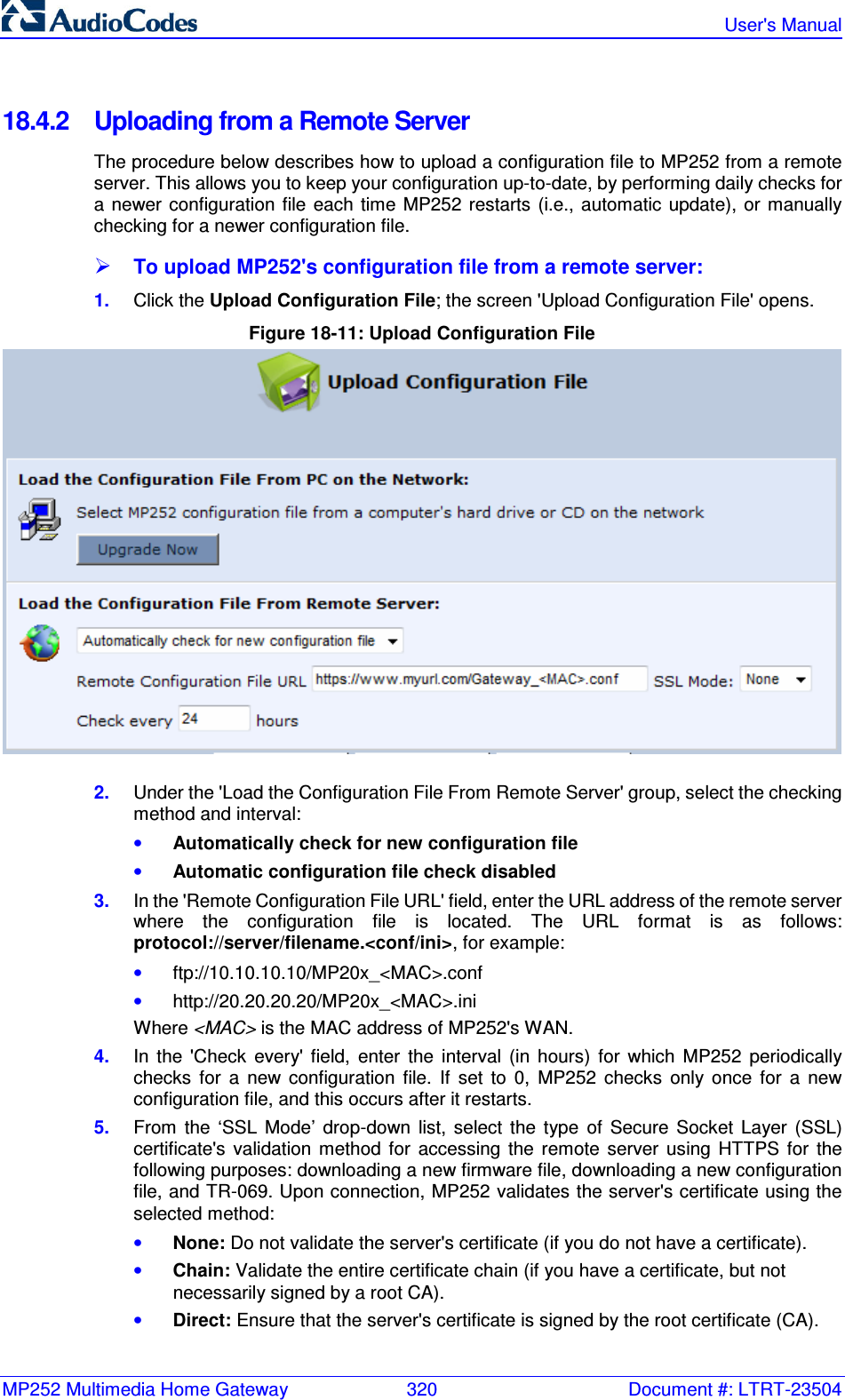
![MP252 Multimedia Home Gateway 17. Add-On Servers and Disk Management Version 3.4.0 307 June 2011 4. Click Add; the new printer appears in the 'Print & Fax' screen. Figure 17-52: Print & Fax – New LPD Printer 17.3.3 Storing and Using Printer Drivers As explained earlier in this chapter, to use a shared printer connected to MP252, a driver for the printer must be installed on the LAN computer from which the print job is to be sent. You can use the MP252 file server to store printer drivers. The drivers should be uploaded from a Windows computer and stored in the system storage area that you have created on one of the disk partitions. The printer can then be installed on other LAN computers using the driver stored on MP252. To upload the driver files to MP252: 1. From Window's Start menu, click Run, and then type "cmd" to open a command shell. 2. At the prompt, type net use to view the list of shares and their status. 3. Type net use /del \\mp252\share-B to delete the specific network mapping entry. Alternatively, you can use net use /del * to delete all network mapping entries. 4. Type net use * \\openrg\print$ [Admin's password] [/user:admin]. This ensures that you are logged into the print server using the Admin user and have the permissions to upload files.](https://usermanual.wiki/VTech-Telecommunications/80-7597-01.User-Manual-2/User-Guide-1590998-Page-107.png)
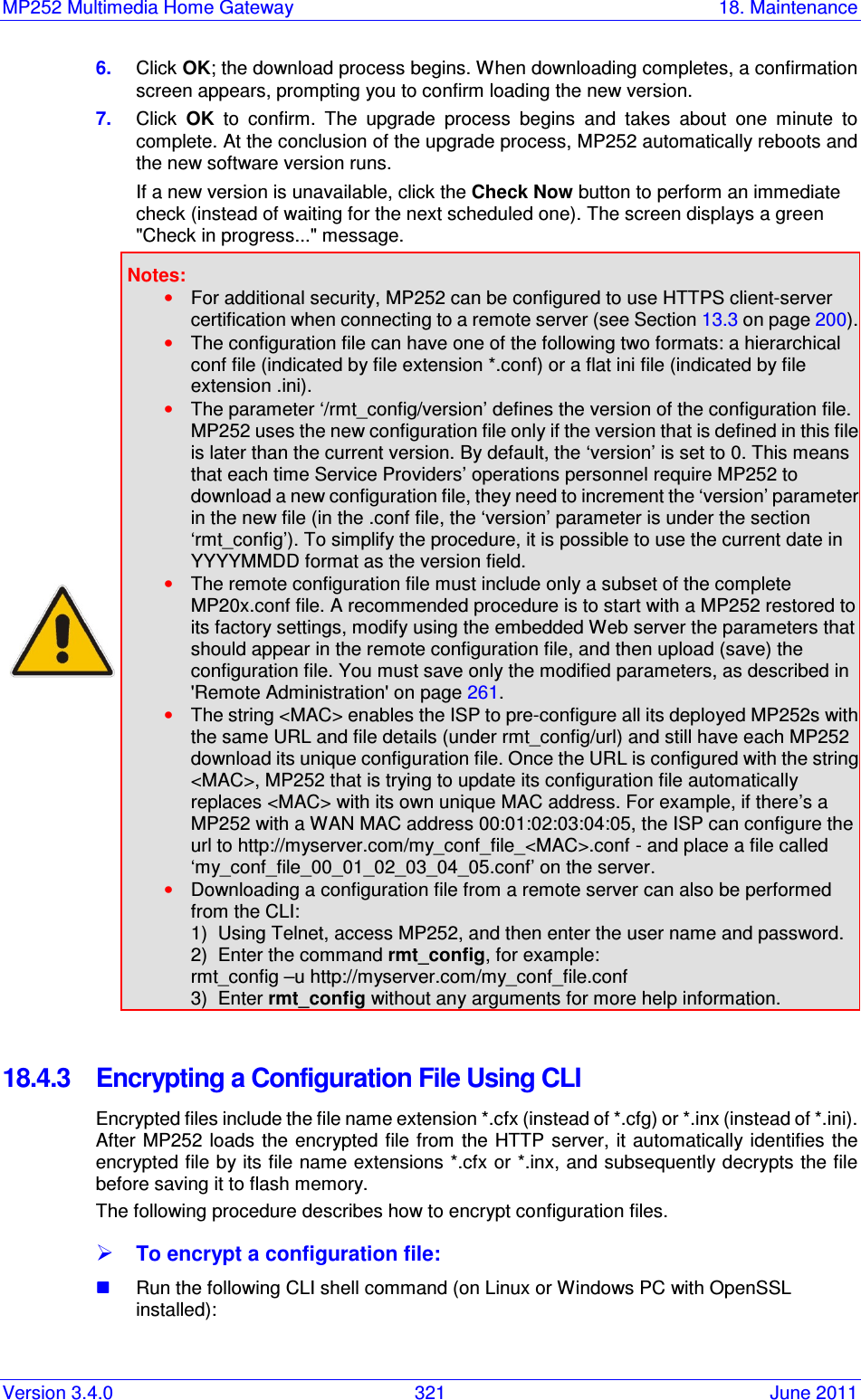
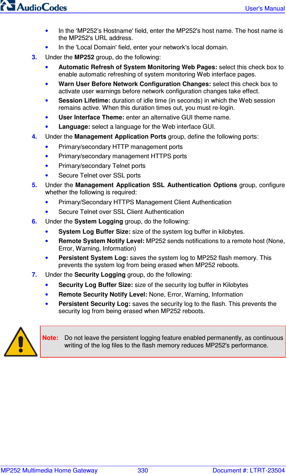
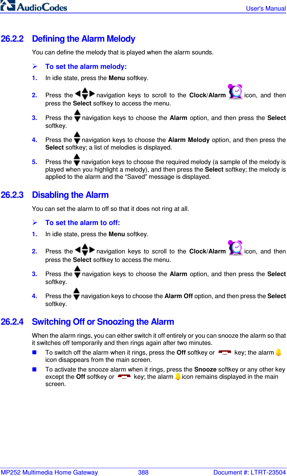
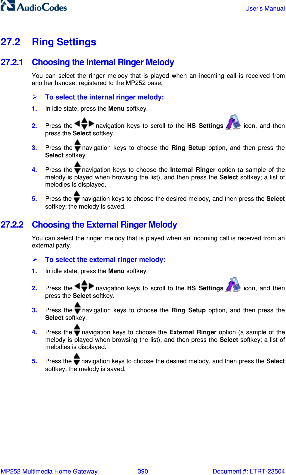
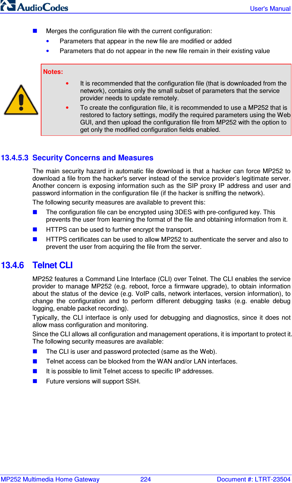
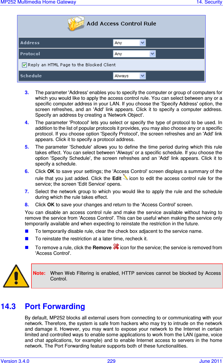
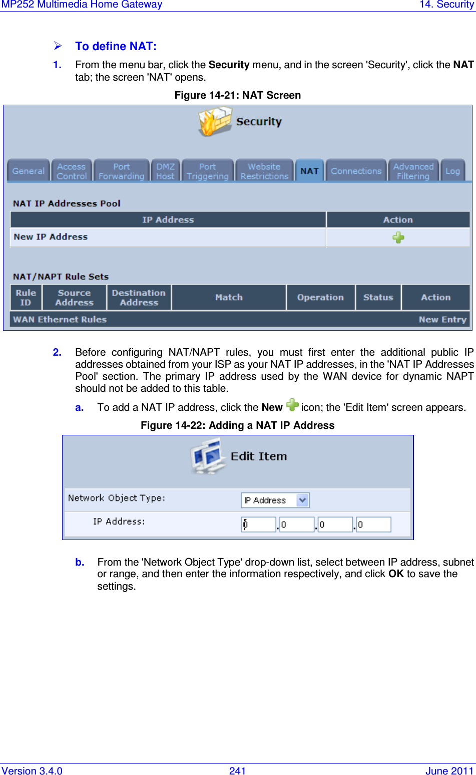
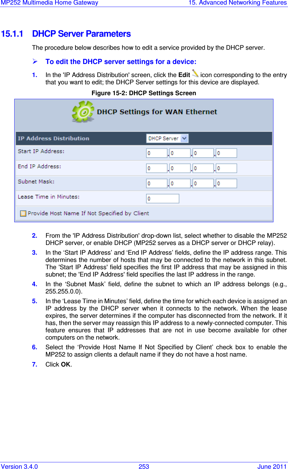
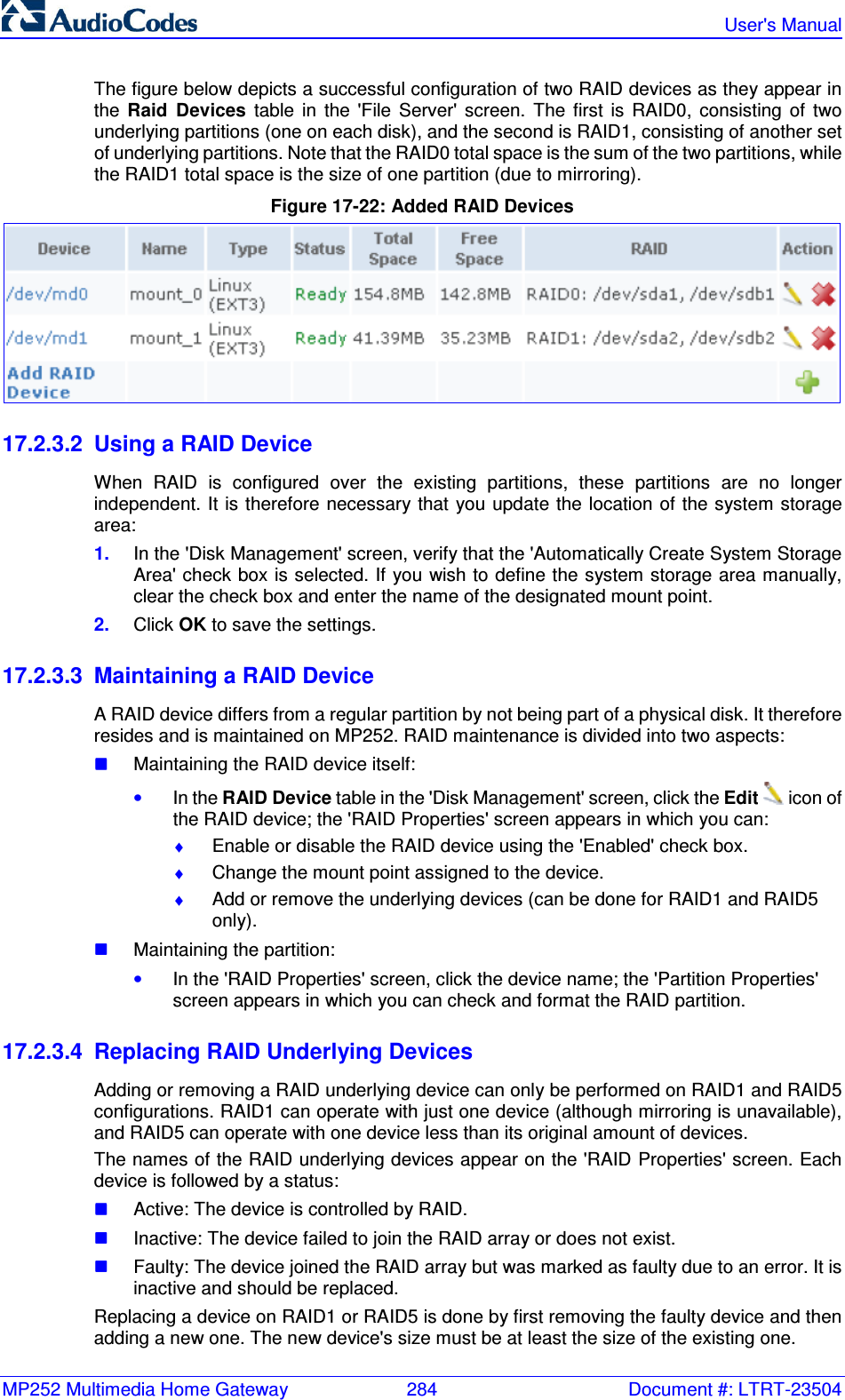
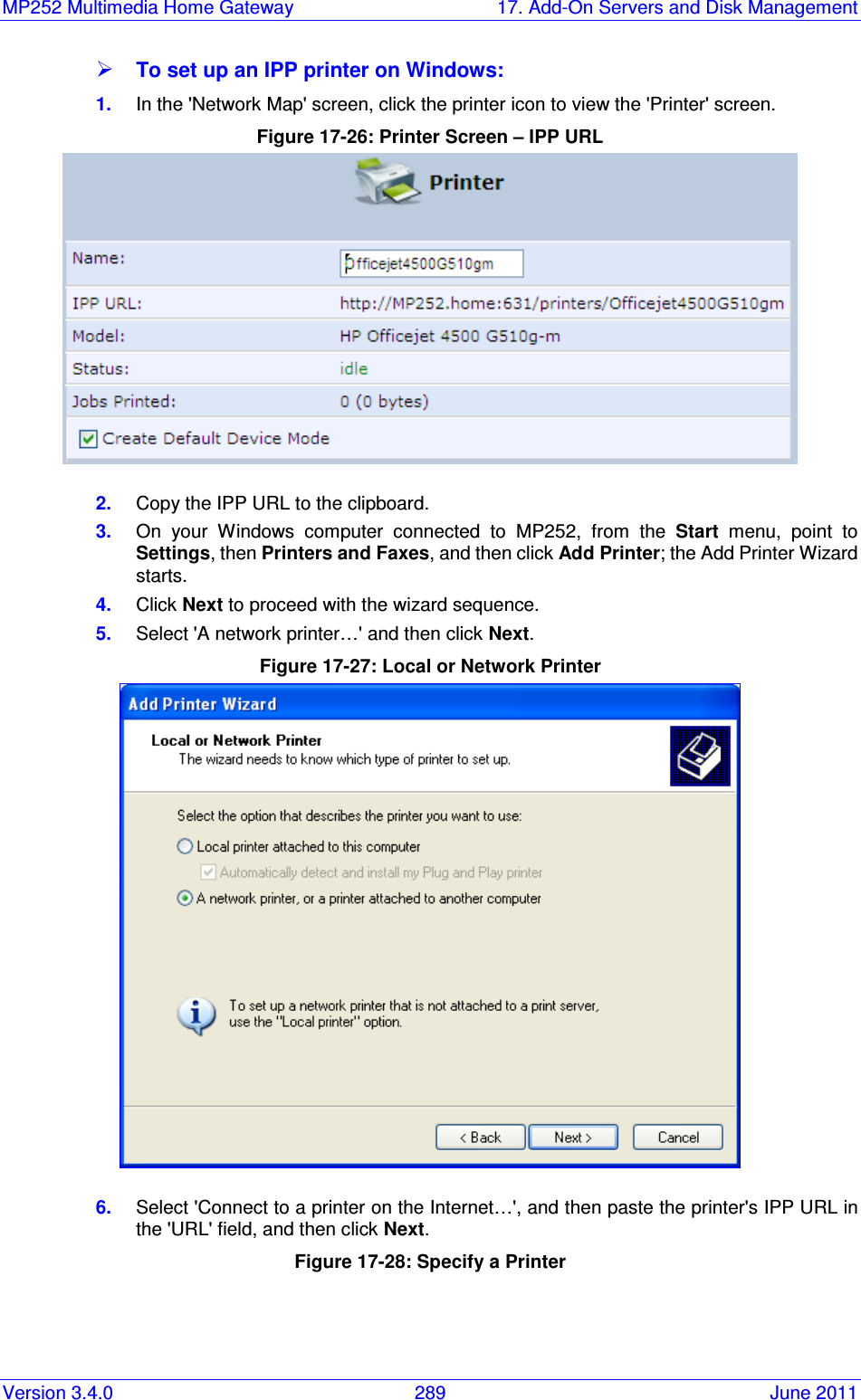
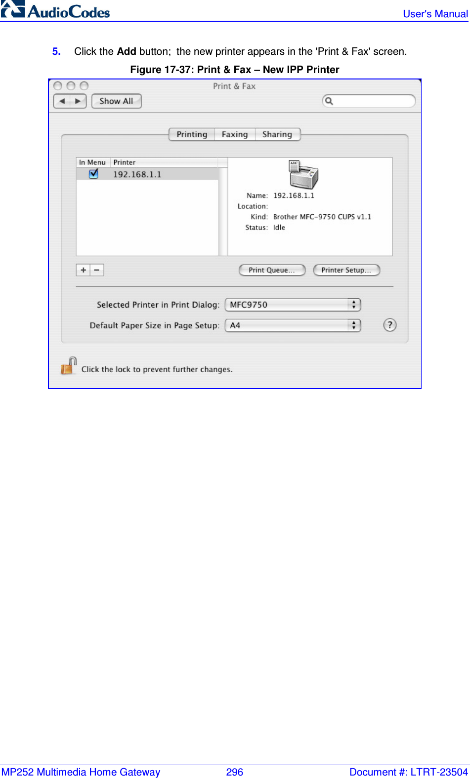
![MP252 Multimedia Home Gateway 322 Document #: LTRT-23504 User's Manual openssl des3 -in <original file> -out <encrypted file> -k <password> -S <salt value> Where, • <original file> is the original clear-text configuration file (*.cfg or *.ini file). • <encrypted file> is the output file (an encrypted *.cfx or *.inx file). • <password> is the password that is used to encrypt the file. • <salt value> is the 8 bytes of a special key value that is combined with the password. The format is 16 hexadecimal digits [0-9,A-F]. An example of this command is shown below: openssl des3 -in c:\temp\try_enc_conf.cfg -out c:\temp\try_enc_conf.cfx -k MyPassword123456 -S 0123456789ABCDEF Notes: • You can choose any <salt value> – MP252 does not have to know about it. • A password can be pre-configured in MP252, using the following CLI command: rg_conf_set_obscure /rmt_config/password <password> • You can also define the password in a configuration file that you download from the server. • If you don’t define a password in the configuration file, a default password is used. Different default passwords are defined per customer, according to the config-file url hostname.](https://usermanual.wiki/VTech-Telecommunications/80-7597-01.User-Manual-2/User-Guide-1590998-Page-122.png)