VEGA Americas PULS616263 VEGAPULS 61/62/63 Radar Sensor User Manual Part 90
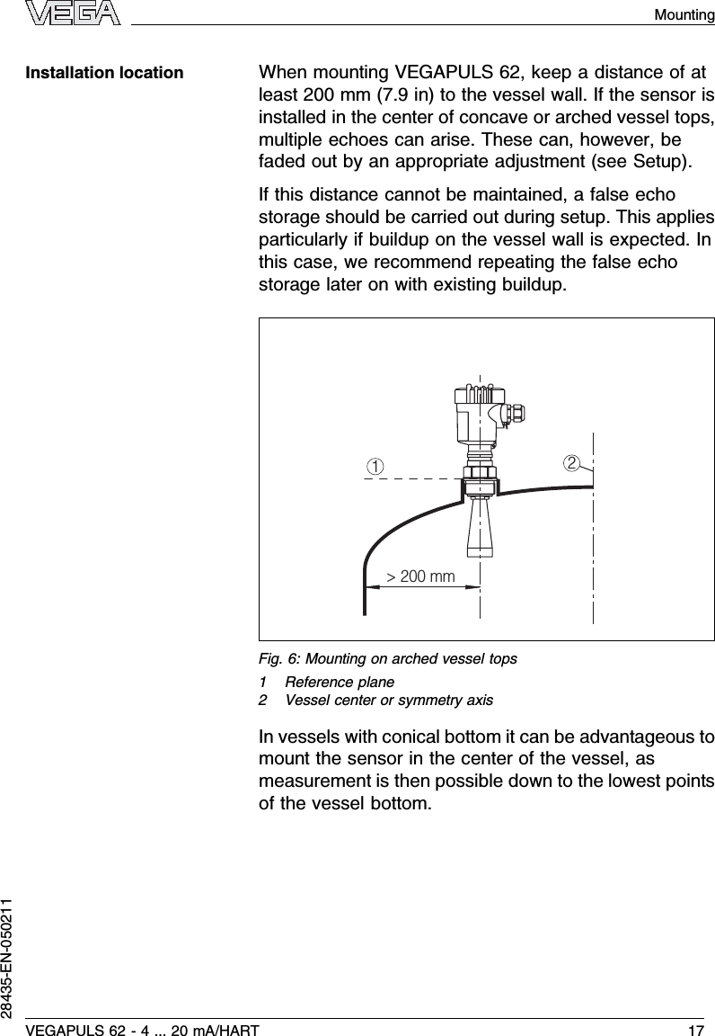
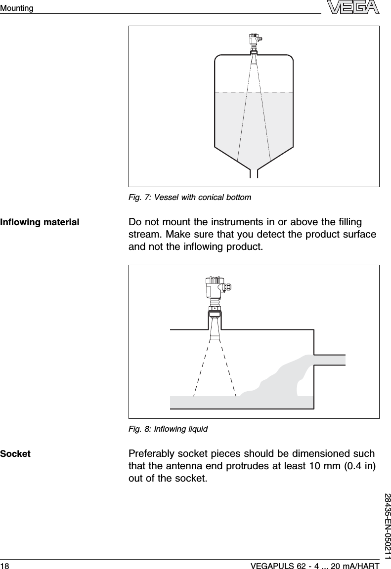
VEGA Americas Inc. VEGAPULS 61/62/63 Radar Sensor Part 90
UserManual.wiki
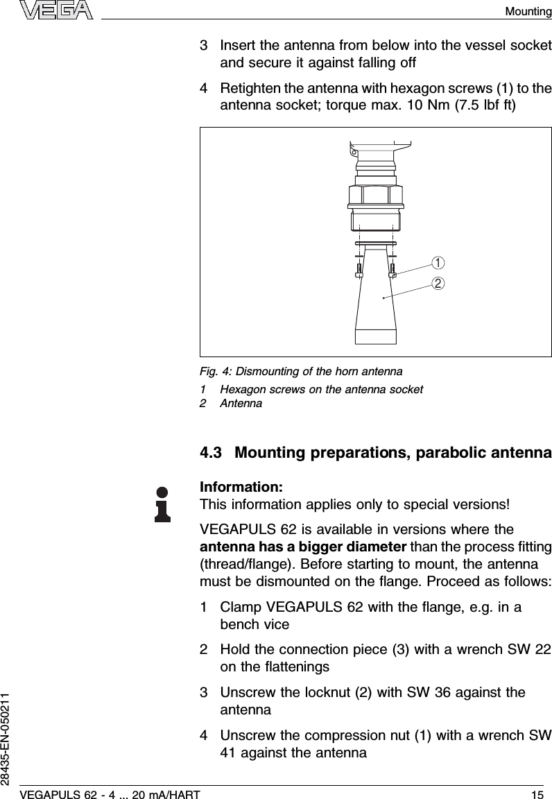
>
VEGA Americas
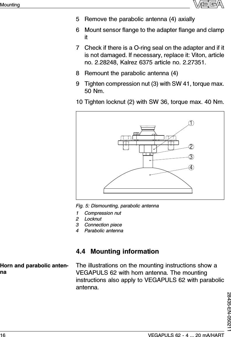
>
PULS616263 User Manual
>
Manuals
Contents
1.
Users Manual
2.
Manuals
Manuals
Navigation menu
Upload a User Manual
Namespaces
Wiki Guide
HTML
PDF
Info
Views
User Manual
Discussion / Help
Navigation
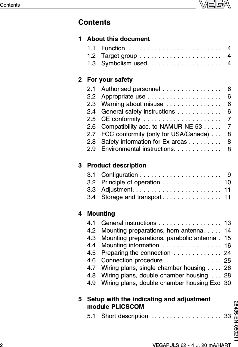
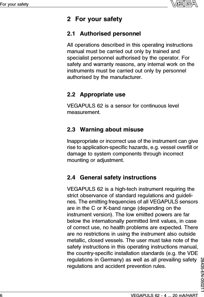

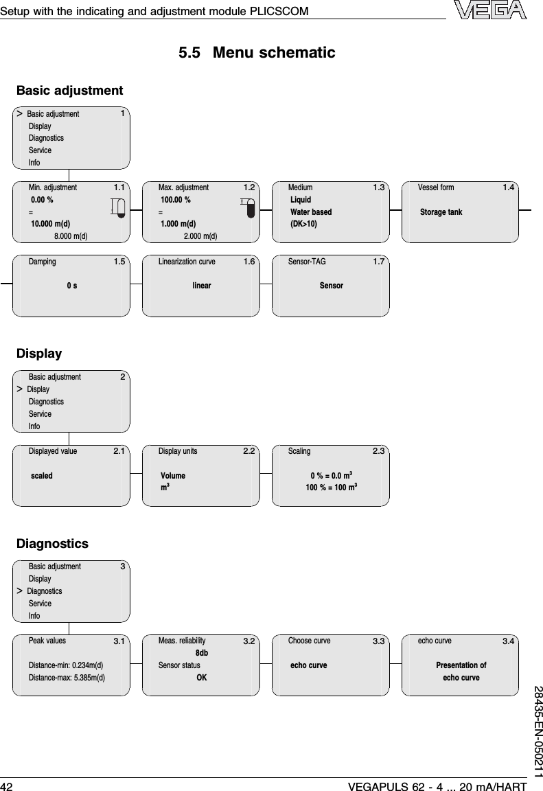
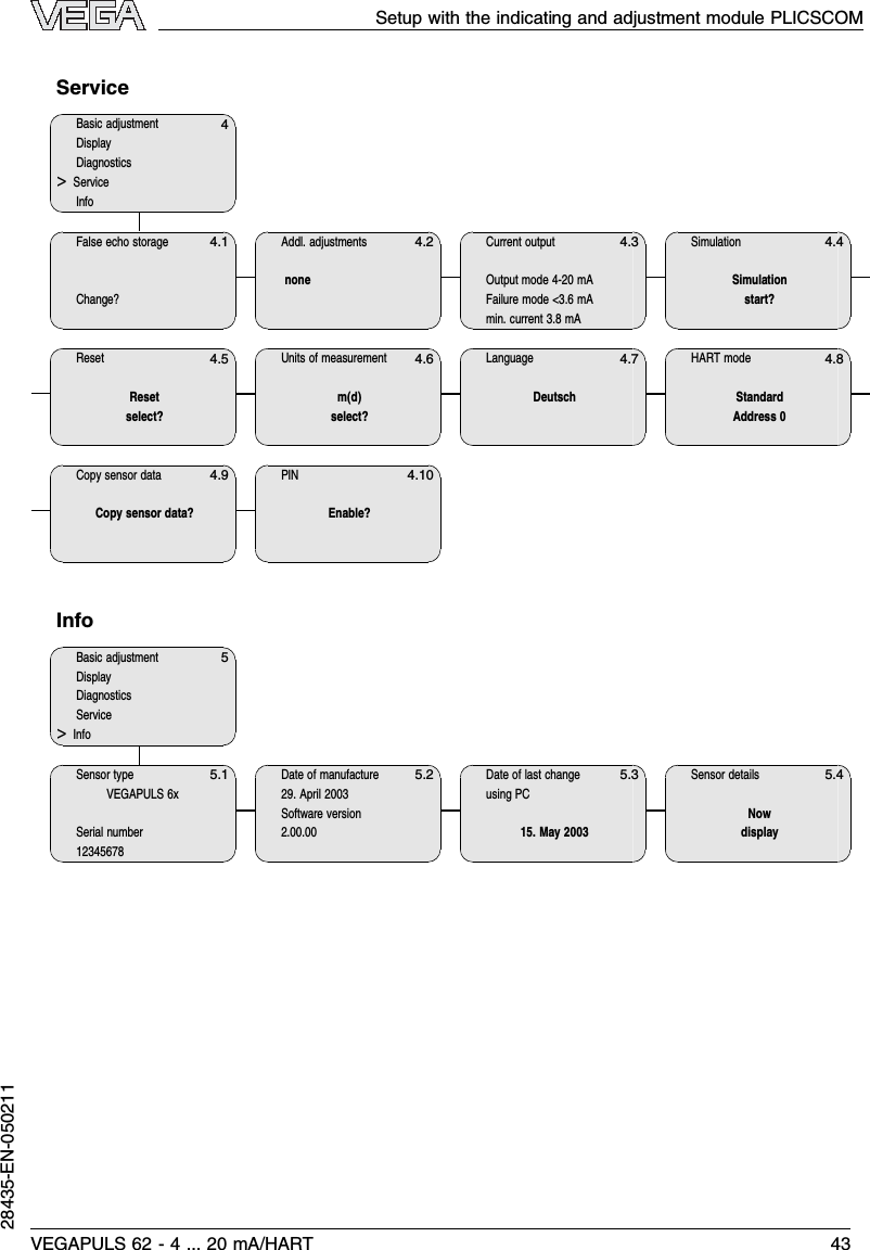
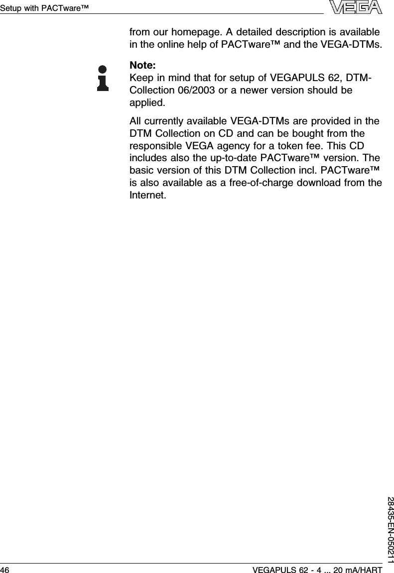
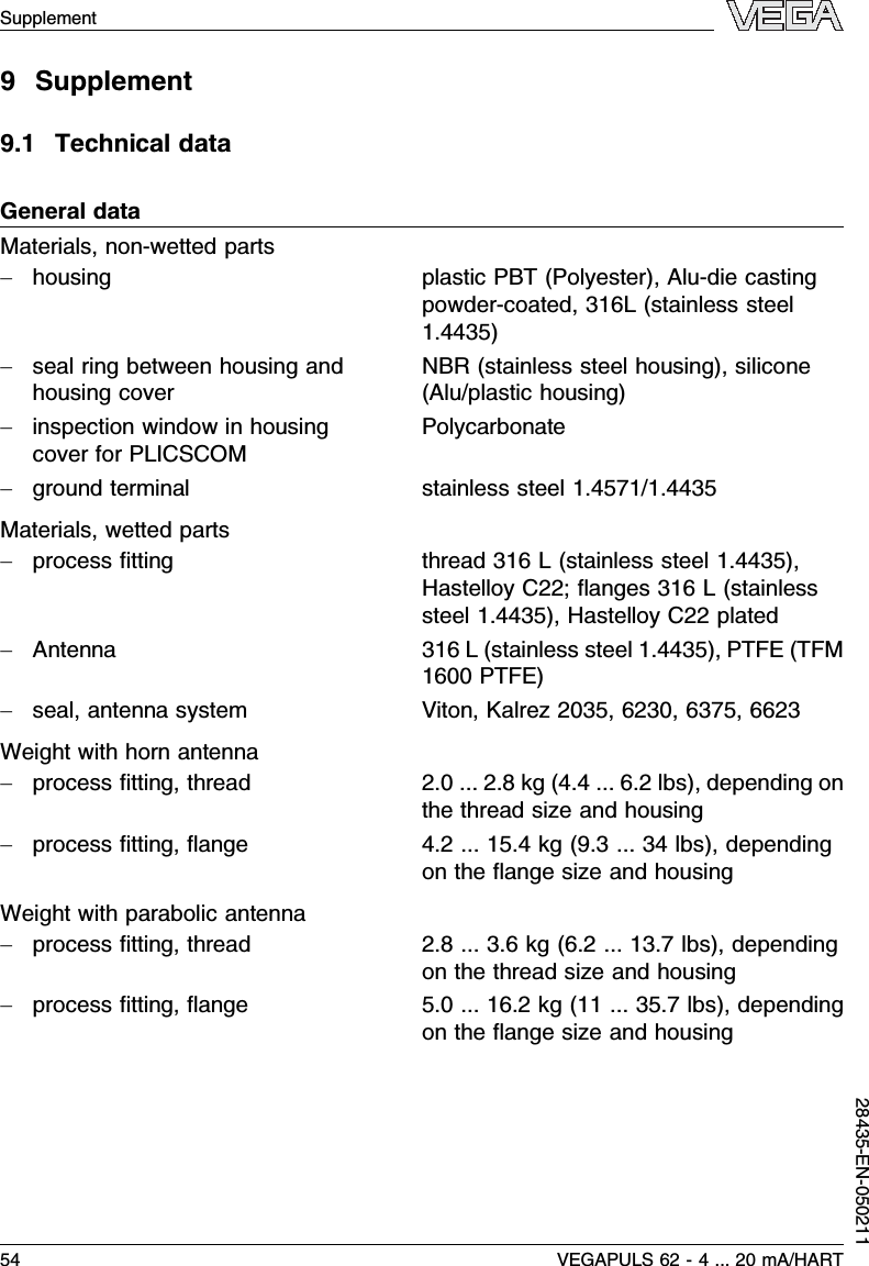
![5.3Adjustment system1.1231Fig.29:Indicating and adjustment elements1LC display2Indication of the menu item number3Adjustment keysl[OK]key:-move to the menu overview-confirm selected menu-edit parameter-save valuel[–>]key to select:-menu change-list entry-editing positionl[+]key:-modify value of a parameterl[ESC]key:-interrupt input-jump to the next higher menuThe sensor is adjusted via the four keys of the indicatingand adjustment module PLICSCOM.The LC displayindicates the individual menu items.The functions of theindividual keys are shown in the above illustration.Approx.10 minutes after the last pressing of a key,anautomatic reset to measured value indication is trigger-Key functionsAdjustment systemVEGAPULS 62 -4... 20 mA/HART 35Setup with the indicating and adjustment module PLICSCOM28435-EN-050211](https://usermanual.wiki/VEGA-Americas/PULS616263.Manuals/User-Guide-525696-Page-36.png)
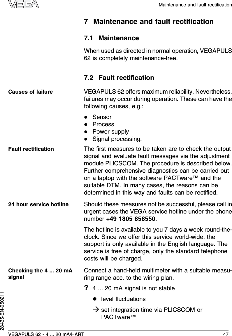
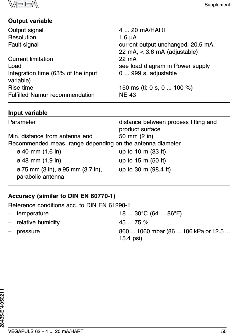
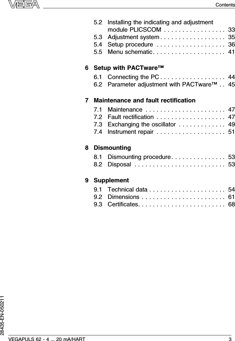
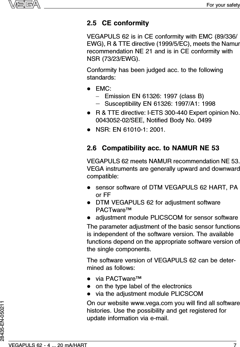
![ed.Any values not confirmed with [OK]will not besaved.5.4Setup procedureAfter VEGAPULS 62 is connected to power supply orafter voltage recurrence,the instrument carries out aself-test for approx.30 seconds.The following steps arecarried out:linternal check of the electronicslindication of the instrument type,the firmware versionas well as the sensor TAGs(sensor name)lOutput signal jumps briefly(approx.10 seconds)tothe set interference current.Then the actual measured value is displayed and thecorresponding current is transmitted to the cable1)InHART-Multidrop mode (several sensors on one input)the address must be set before continuing with theparameter adjustment.You will find a detailed descrip-tion in the operating instructions manual of PLICSCOMor in the online help of PACTware™or DTM.HART modeStandardAddress 0Because VEGAPULS 62 is a distance measuringinstrument,the distance from the sensor to the productsurface is measured.In order to have the actual leveldisplayed,an allocation of the measured distance to thepercentage height must be carried out.To make thisadjustment,the full and empty distances in the vesselare entered.If these values are not known,it is alsopossible to carry out the adjustment with other distan-ces,e.g.10 %and 90 %.Starting point of these distancevalues is always the seal surface of the thread or flange.The actual level is then calculated on the basis of these1)The values correspond to the actual level as well as to the settingsalready carried out,e.g.default setting.Switch on phaseAddress setting HART-MultidropParameter adjustment36 VEGAPULS 62 -4... 20 mA/HARTSetup with the indicating and adjustment module PLICSCOM28435-EN-050211](https://usermanual.wiki/VEGA-Americas/PULS616263.Manuals/User-Guide-525696-Page-37.png)
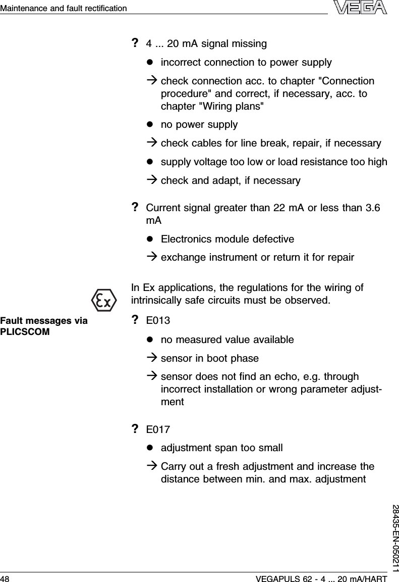
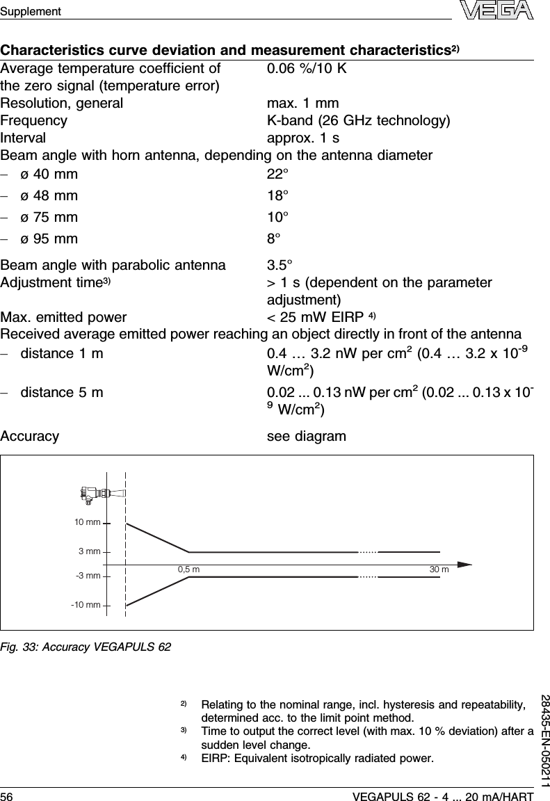
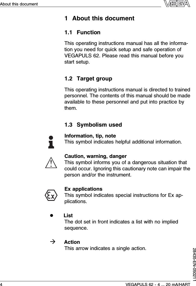
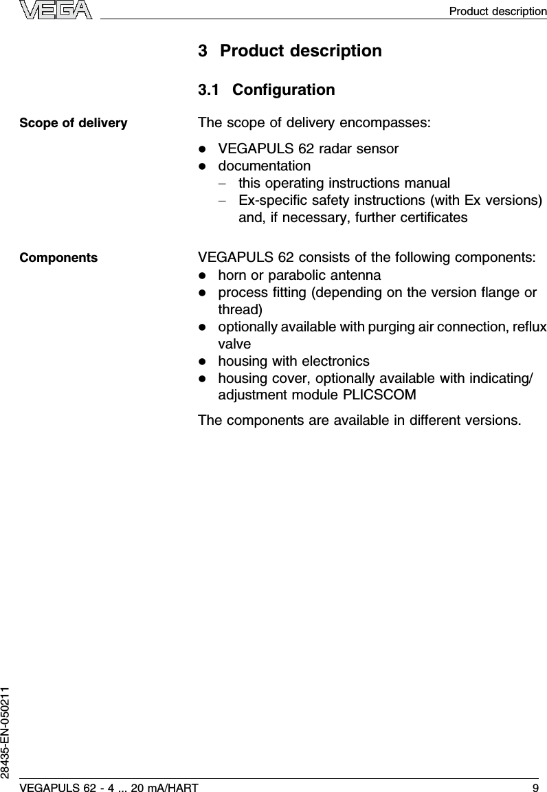
![entered values.At the same time,the operating range ofthe sensor is limited from maximum range to therequested range.The real product level during this adjustment is notimportant,because the min./max.adjustment is alwayscarried out without changing the product level.Thesesettings can be made ahead of time without theinstrument having to be installed.In the main menu item Basic adjustment,the individualsubmenu items should be selected one after the otherprovided with the correct parameter values.Start your parameter adjustment with the following menuitems of the basic adjustment:Proceed as follows:1Move from the measured value display to the mainmenu by pushing [OK].>Basic adjustmentDisplayDiagnosticsServiceInfo2Select the menu item Basic adjustment with [–>]andconfirm with [OK].Now the menu item min.adjust-ment is displayed.Min.adjustment0.00 %=5.000 m(d)4.000 m(d)3Prepare the percentage value for editing with [OK]and set the cursor to the requested position with [–>].Set the requested percentage value with [+]andsave with [OK].The cursor jumps now to thedistance value.4Enter the appropriate distance value in m (corre-sponding to the percentage value)for the emptyvessel (e.g.distance from the sensor to the vesselbottom).Carrying out min.adjust-mentVEGAPULS 62 -4... 20 mA/HART 37Setup with the indicating and adjustment module PLICSCOM28435-EN-050211](https://usermanual.wiki/VEGA-Americas/PULS616263.Manuals/User-Guide-525696-Page-38.png)
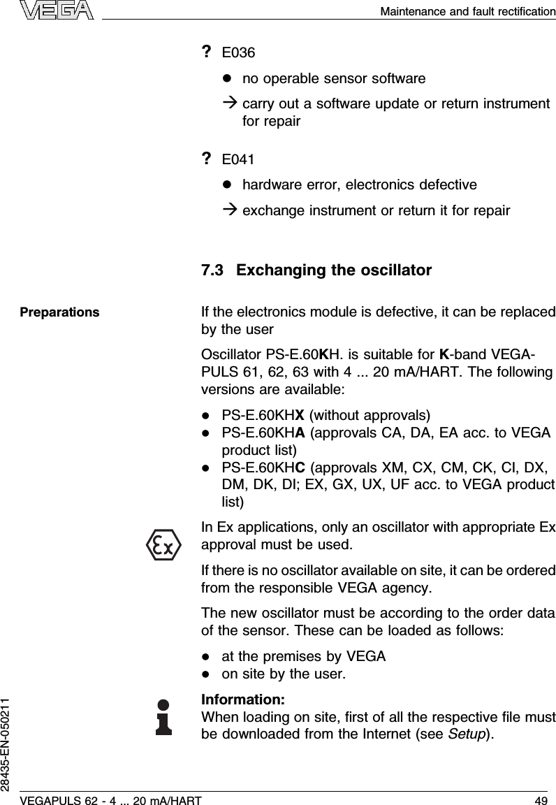
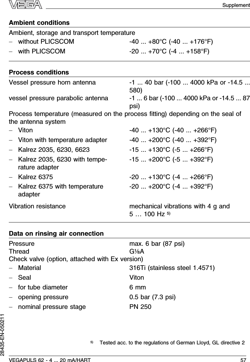
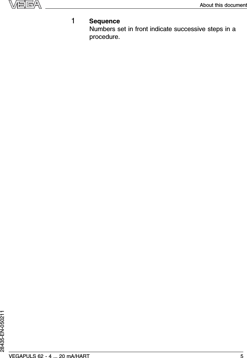
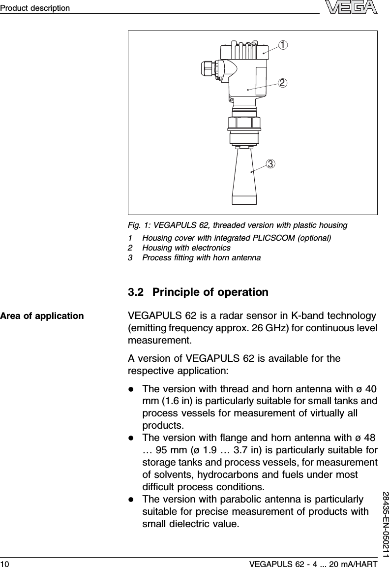
![5Save the settings with [OK]and move to max.adjustment with [–>].Proceed as follows:Max.adjustment100.00 %=1.000 m(d)2.000 m(d)1Prepare the percentage value for editing with [OK]and set the cursor to the requested position with [–>].Set the requested percentage value with [+]andsave with [OK].The cursor jumps now to thedistance value.2Enter the appropriate distance value in m (corre-sponding to the percentage value)for the full vessel.Make sure that the max.level must be beneath thedead zone.3Save the settings with [OK]and move to the mediumselection with [–>].Each product has different reflective properties.Inliquids additional interfering factors are fluctuatingproduct surfaces and foam generation.In solids,this isthe dust generation,material cone and additionalechoes caused by the vessel wall.To adapt the sensorto the different applications,you should choose in thismenu item Liquid or Solid.MediumLiquidAccording to the conductivity and the dielectric constantvalue of liquids,the reflection properties can differconsiderably.Therefore additional option such asSolvent,Chem.mixture and Water based are offeredbelow the menu item Liquid.For solids you choose also Powder/Dust,Granular/Pellets or Ballast/Pebbels.Carrying out max.adjust-mentMedium selection38 VEGAPULS 62 -4... 20 mA/HARTSetup with the indicating and adjustment module PLICSCOM28435-EN-050211](https://usermanual.wiki/VEGA-Americas/PULS616263.Manuals/User-Guide-525696-Page-39.png)
![With the medium selection,the sensor is adaptedperfectly to the product and the reliability,particularly inproducts with bad reflective properties is considerablyincreased.Enter the requested parameter via the respective keys,save your settings and jump to the next menu item withthe [–>]key.Apart from the medium also the vessel form caninfluence the measurement.To adapt the sensor tothese conditions,this menu item offers (depending oneither liquid or solid is selected)different options.ForLiquid these are Storage tank,Stilling tube,Open vesselor Stirred vessel,for Solid Silo or Bunker.Vessel formStorage tankEnter the requested parameter via the respective keys,save your settings and jump to the next menu item withthe [–>]key.To suppress fluctuation in the measured value display,e.g.by agitated product surfaces,an integration timecan be set.This time can be between 0and 999seconds.Please note that the reaction time of the entiremeasurement will be longer and the sensor will react toquick changes of the measured value with a corre-sponding delay.In general,a time of a few seconds issufficient to smooth the measured value display.Damping0sEnter the requested parameter via the respective keys,save your settings and jump to the next menu item withthe [–>]key.Vessel formDampingVEGAPULS 62 -4... 20 mA/HART 39Setup with the indicating and adjustment module PLICSCOM28435-EN-050211](https://usermanual.wiki/VEGA-Americas/PULS616263.Manuals/User-Guide-525696-Page-40.png)
![Alinearization is necessary for all vessels in which thevessel volume does not increase linearly with the level -e.g.in a cylindrical or spherical tank -and the indicationor output of the volume is requested.Correspondinglinearization curves are preprogrammed for thesevessels.They represent the correlation between thelevel percentage and vessel volume.By activating theappropriate curve,the volume percentage of the vesselis displayed correctly.If the volume should not bedisplayed in percent but e.g.in l or kg,a scaling can beset in the menu item Display.Linearization curvelinearEnter the requested parameter via the respective keys,save your settings and jump to the next menu item withthe [–>]key.In this menu item you can enter an unambiguousdesignation for the sensor,e.g.the measurement loopname or the tank or product designation.In digitalsystems and in the documentation of larger plants,aunique designation should be entered for exact identi-fication of individual measuring sites.Sensor-TAGSensorWith this menu item,the Basic adjustment is finishedand you can now jump to the main menu with the [ESC]key.High sockets or vessel installations,such as e.g.strutsor agitators as well as buildup and weld joints on thevessel walls cause false reflections which influence themeasurement.Afalse echo storage detects and marksthese false echoes so that they are no longer taken intoLinearization curveSensor-TAGFalse echo storage40 VEGAPULS 62 -4... 20 mA/HARTSetup with the indicating and adjustment module PLICSCOM28435-EN-050211](https://usermanual.wiki/VEGA-Americas/PULS616263.Manuals/User-Guide-525696-Page-41.png)
![account for the level measurement.Afalse echomemory should be created with empty vessel so that allprobably existing false reflections can be detected.False echo storageChange?Proceed as follows:1Move from the measured value display to the mainmenu by pushing [OK].2Select the menu item Service with [–>]and confirmwith [OK].Now the menu item false echo storage isdisplayed.3Confirm False echo storage -Change now with [OK]and select in the below menu Create new.Enter theactual distance from the sensor to the productsurface.All false echoes in this area are detected bythe sensor and saved after confirming with [OK].Note:Check the distance to the product surface as in case ofawrong(too big)setting,the real level will be saved asfalse echo.Hence the level can no longer be detected inthis area.Additional adjustment and diagnosis options such as e.g.scaling,simulation or trend curve presentation areshown in the following menu schematic.You will find adetailed description of these menu items in the operatinginstructions manual of the indicating and adjustmentmodule PLICSCOM.Optional settingsVEGAPULS 62 -4... 20 mA/HART 41Setup with the indicating and adjustment module PLICSCOM28435-EN-050211](https://usermanual.wiki/VEGA-Americas/PULS616263.Manuals/User-Guide-525696-Page-42.png)