Uniden America UB305C Trunk Tracker Scanner User Manual Pages 56 to 74
Uniden America Corporation Trunk Tracker Scanner Pages 56 to 74
UserManual.wiki
>
Uniden America
>
UB305C User Manual
>
Pages 56 to 74
Contents
1.
Pages 1 to 13
2.
Pages 14 to 26
3.
Pages 27 to 39
4.
Pages 40 to 55
5.
Pages 56 to 74
6.
Pages 75 to 99
Pages 56 to 74
Navigation menu
Upload a User Manual
Namespaces
Wiki Guide
HTML
PDF
Info
Views
User Manual
Discussion / Help
Navigation
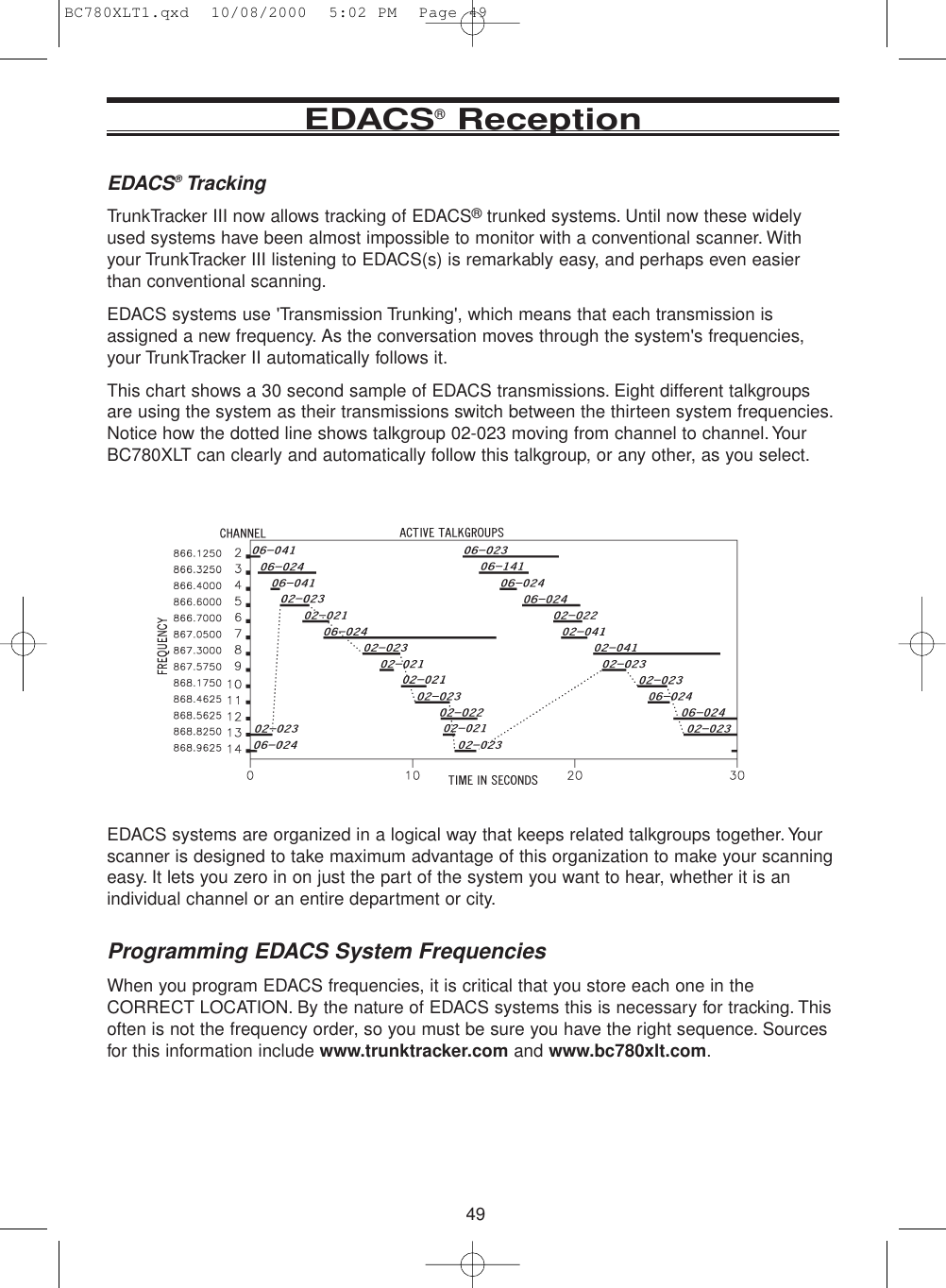
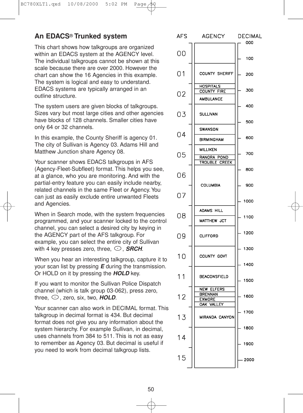
![51Special EDACS®FeaturesAFS Partial Entry FeatureAFS is Uniden's method of encoding EDACS talkgroups. AFS stands for 'Agency-Fleet-Subfleet'.AFS talkgroups are used in all EDACS reception -- in ID SEARCH, ID LOCKOUT and ID SCANscanlists.The powerful AFS Partial Entry feature designed into the BC780XLT lets you use either acomplete talkgroup code, or just the most significant part.This feature lets you expand or narrow searching andscanning to one of 4 levels. By entering only the desiredpart of an AFS talkgroup, you can select 2048 talkgroups,128 talkgroups, 8 talkgroups, or a single talkgroup. Forexample, you could program every talkgroup in a policedepartment with just 4 key presses.You can use the AFSPartial Entry feature anywhere that you need to specify EDACS talkgroup.Your BC780XLT can also enter or display EDACS talkgroups in decimal format (0-2047).Press MENU - TRUNK DATA, and for banks selected as EDACS banks, select Item 8,EDACS ID FORM and change it to Decimal.You can use this feature to translate decimaltalkgroups lists to the much more powerful AFS format.Examples of how you might use AFS are shown above in the description of an EDACStrunked system, and elsewhere in this manual. It is very easy to use. Be sure to becomefamiliar with AFS Partial Entry, and your scanning will become far more flexible and efficient.Emergency Call AlertYour BC780 alerts you when an EDACS Emergency transmission occurs.EDACS systems often provide users with an 'Emergency' button on their radios. Users introuble can alert the dispatcher and other units and get priority access to the radio system.When a user activates Emergency mode your scanner will flash EMERGENCY during theentire transmission. At the beginning of each transmission it will sound a distinctiveemergency alert tone three times.Patch TrackingThe BC780 can follow EDACS patched talkgroups.EDACS systems sometimes bring several talkgroups together in a 'Patch'. A patch might beused by a police agency at night to provide a single channel with a single dispatcher for awide area. A patch is created when a single, temporary talkgroup substitutes for the originaltalkgroups. While the patch is running, which may be for hours or days, the originaltalkgroups cease to be used. If you were monitoring one of these talkgroups, you might think there was no traffic, but in fact the talkgroup was operating at the different temporary number.If a talkgroup in your Scan List is patched, your scanner will continue to receive it under itsnew identity until the patch is ended. When a patch is being received, the radio will display[PATCH ID], and will show the temporary common talkgroup plus all the included talkgroupsin a cycling display. The BC780 is limited to following one patch.The temporary talkgroups used for patches are usually found in AFS code 15-xxx, andsometimes 00-xxx.BC780XLT1.qxd 10/08/2000 5:02 PM Page 51](https://usermanual.wiki/Uniden-America/UB305C.Pages-56-to-74/User-Guide-181939-Page-3.png)