UTStarcom Telecom 6011 Wireless Access Point User Manual
UTStarcom Telecom Co., Ltd. Wireless Access Point
UserManual.wiki
>
UTStarcom Telecom
>
6011 User Manual
>
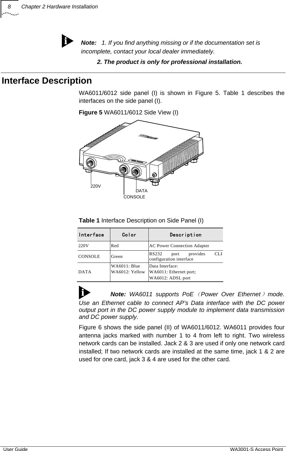
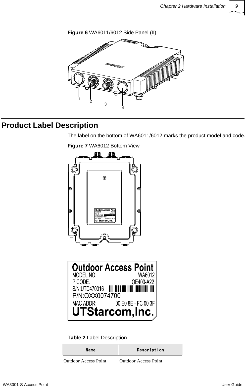
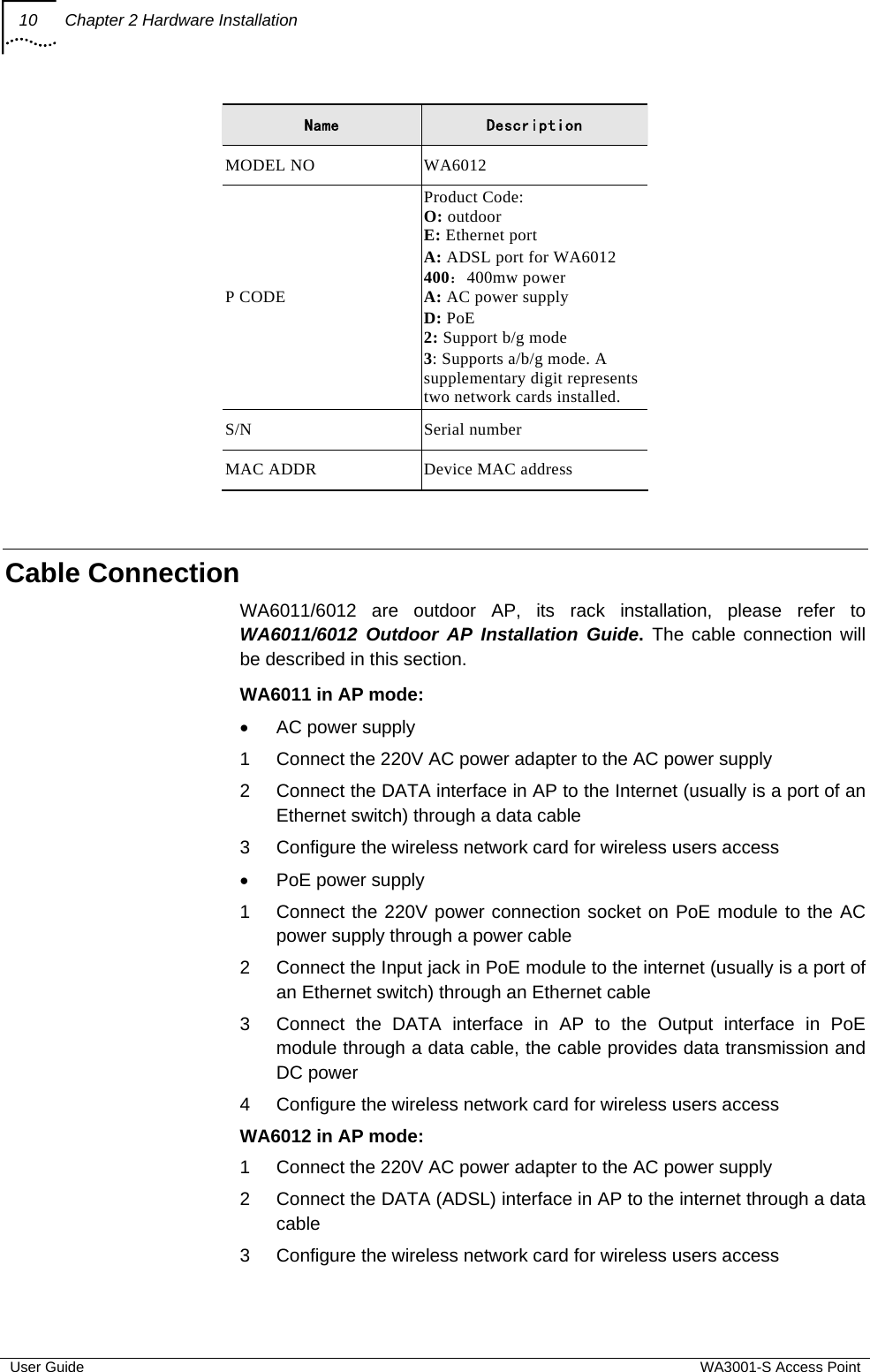
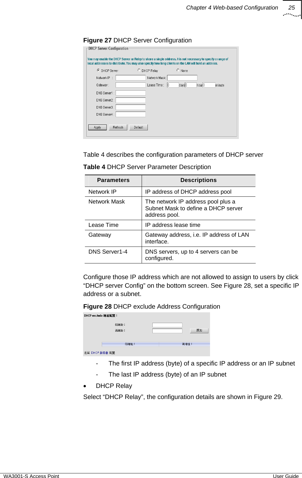
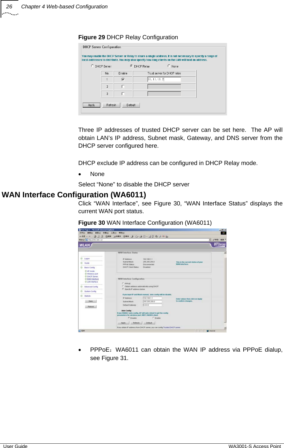
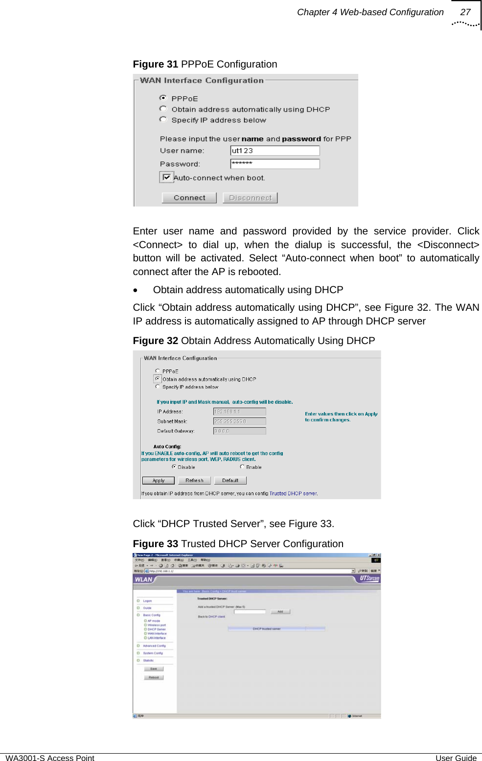
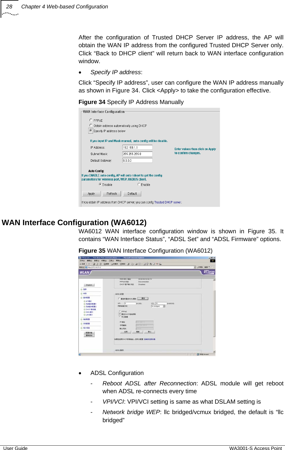
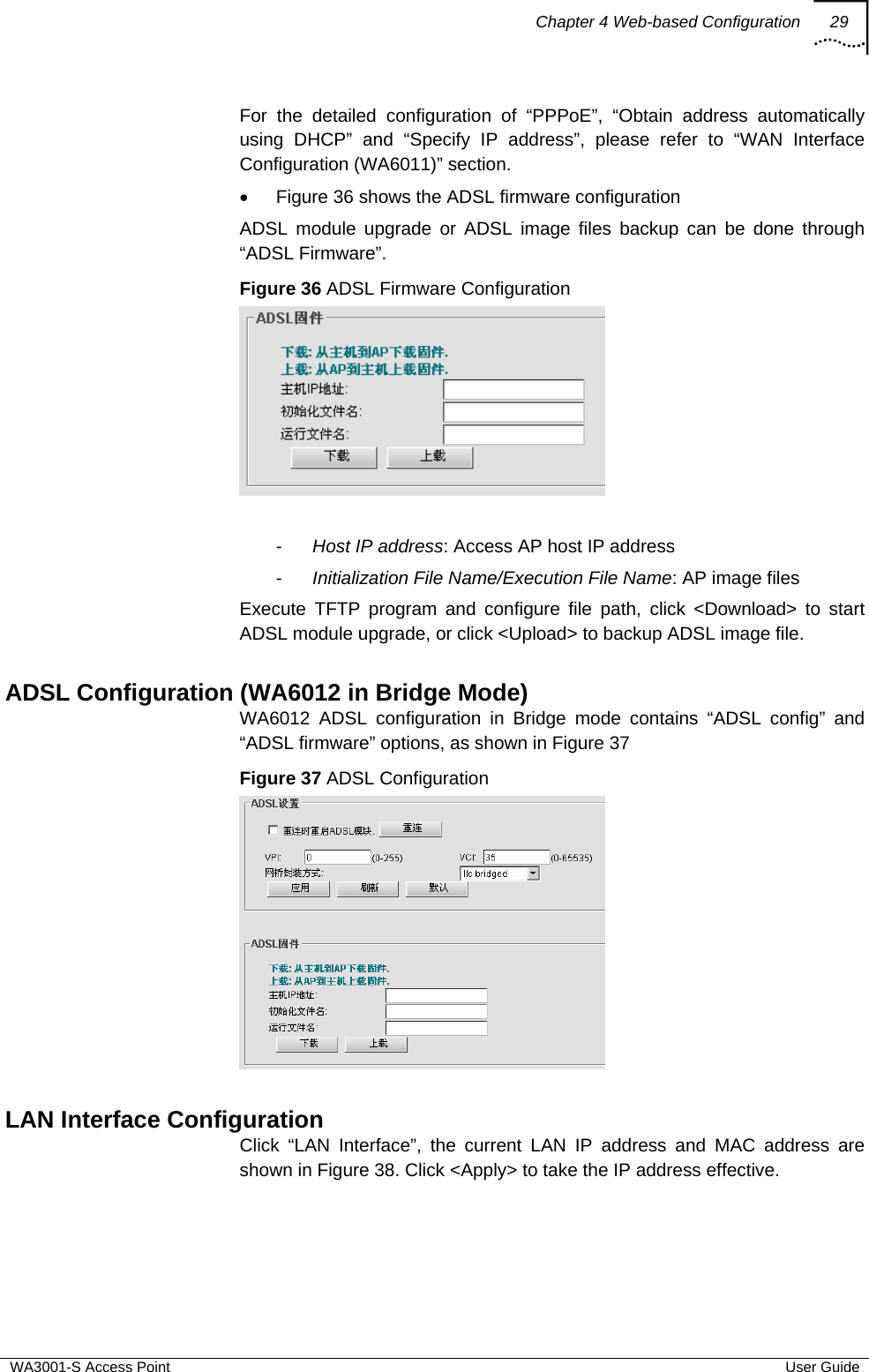
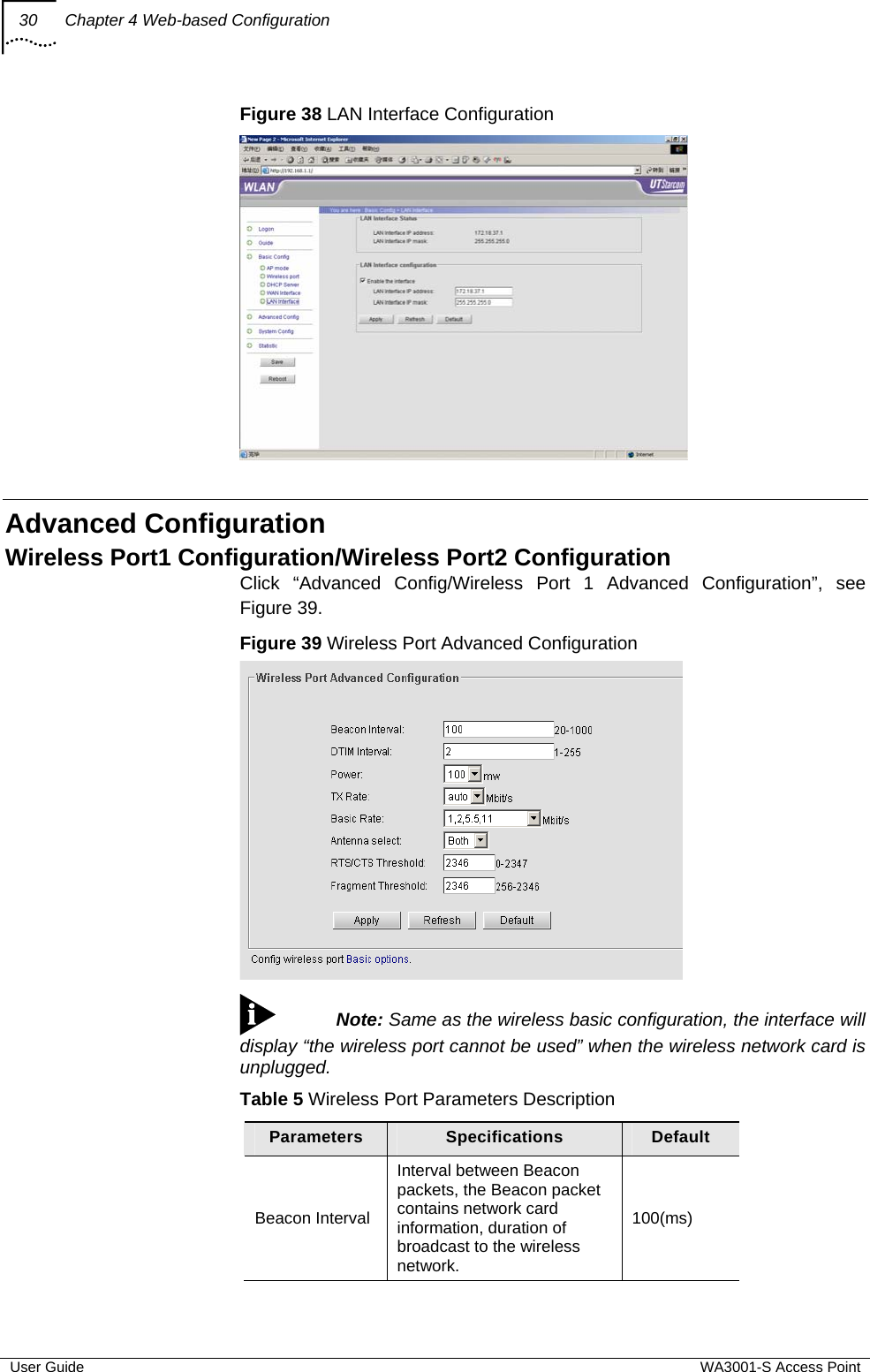
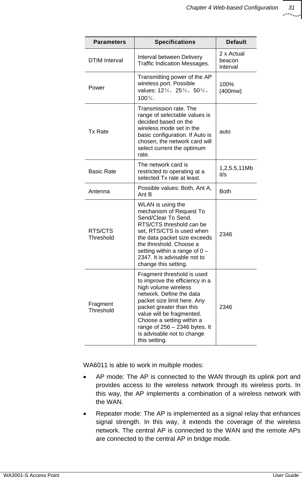
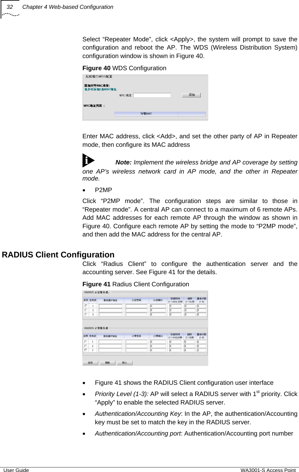
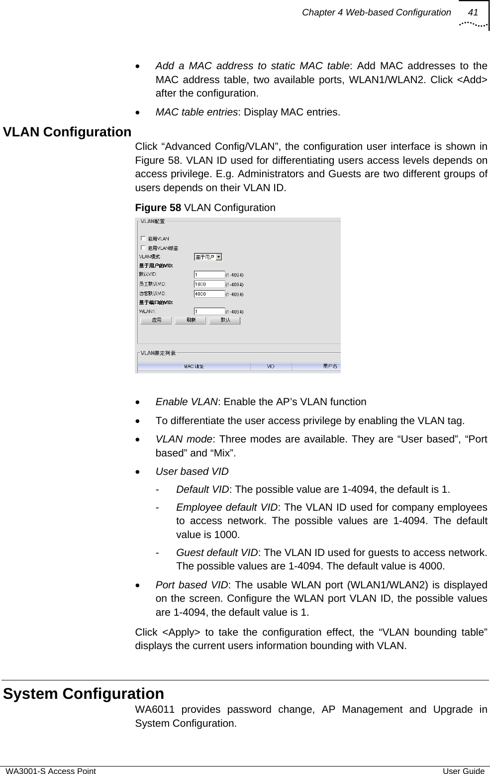
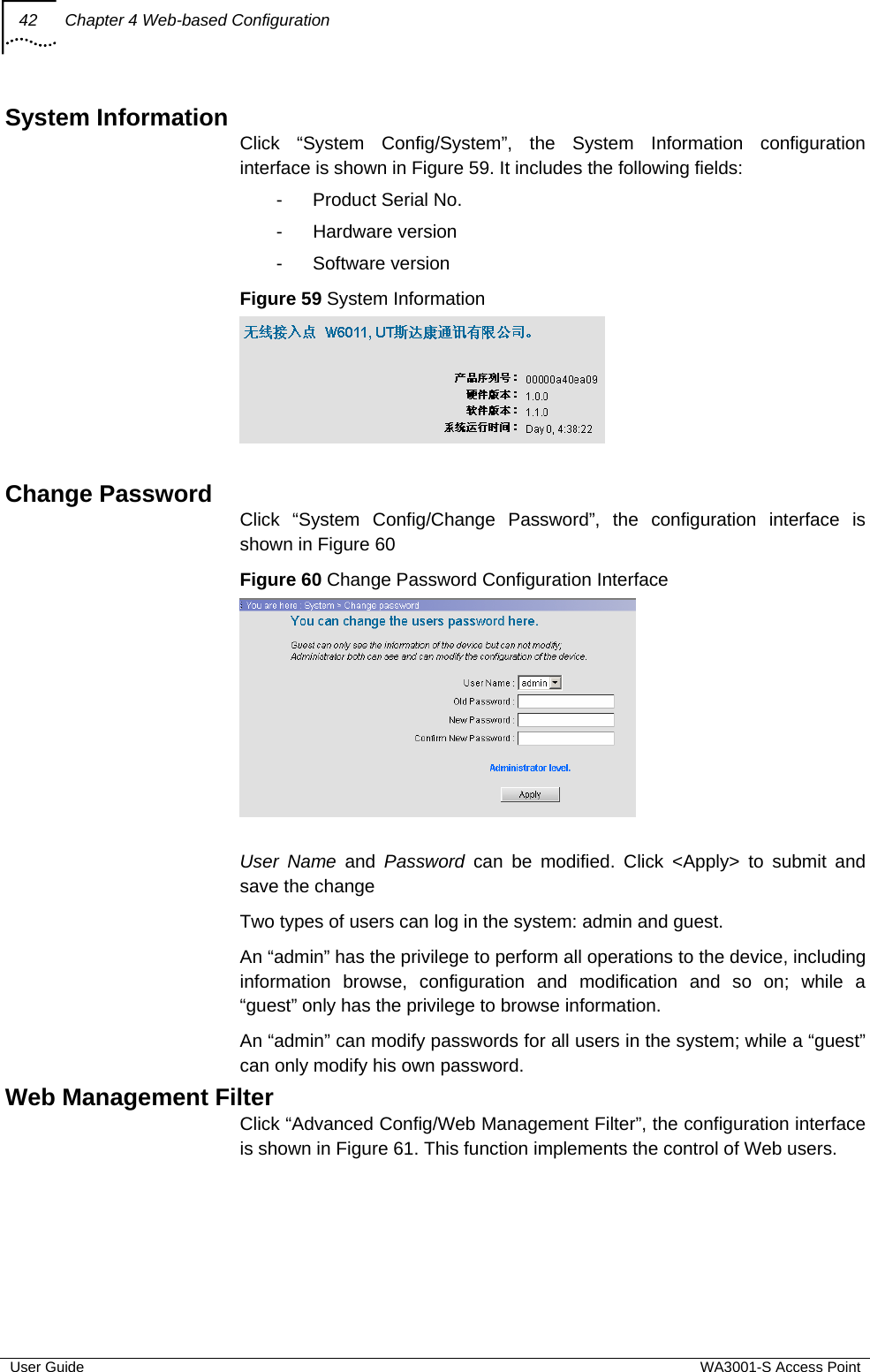
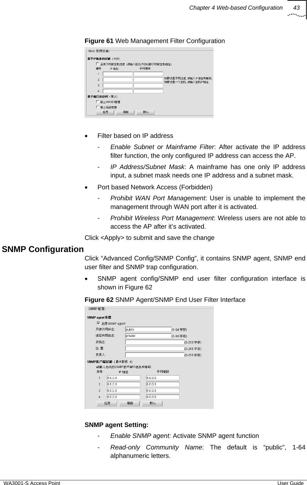
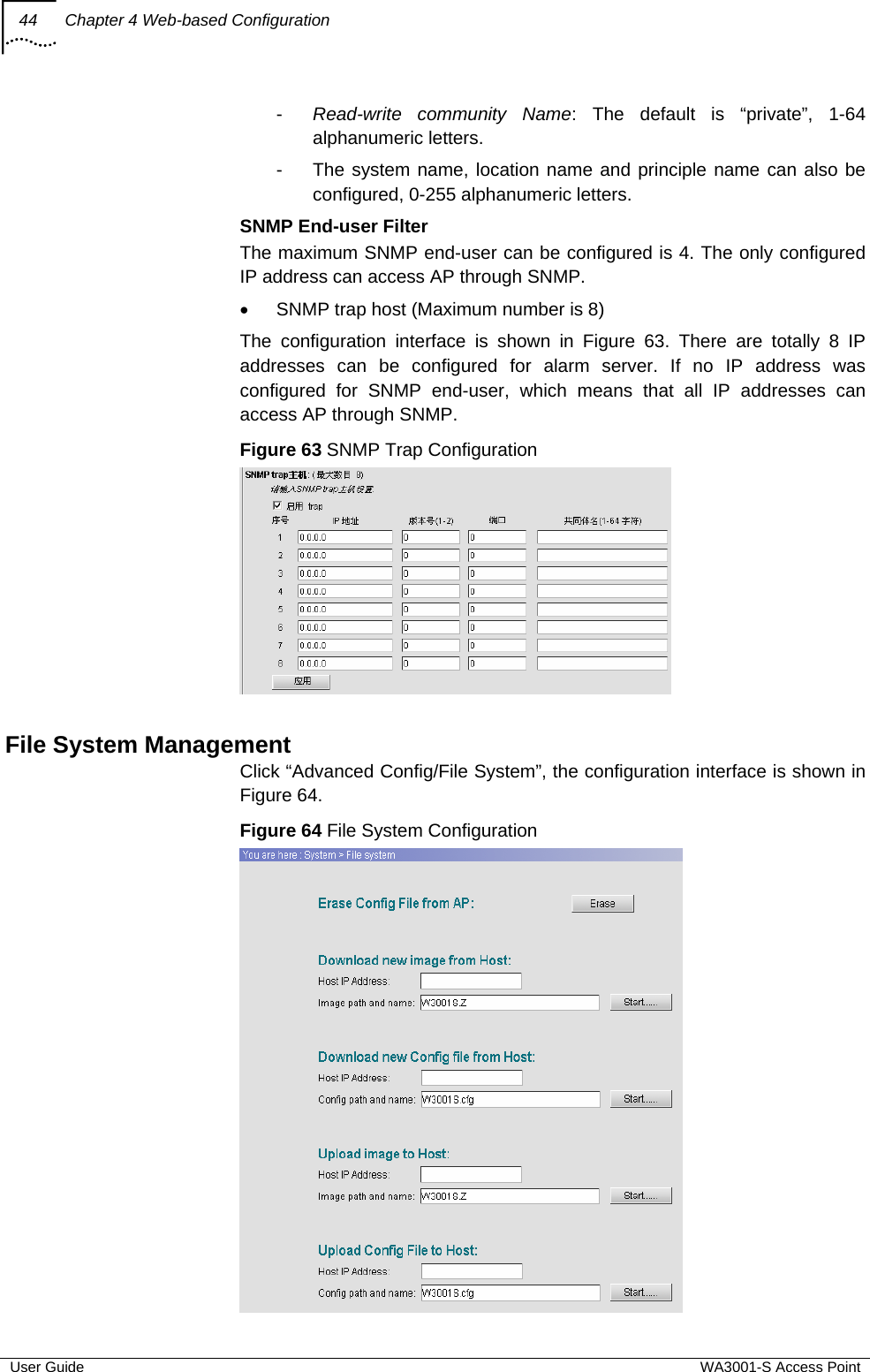
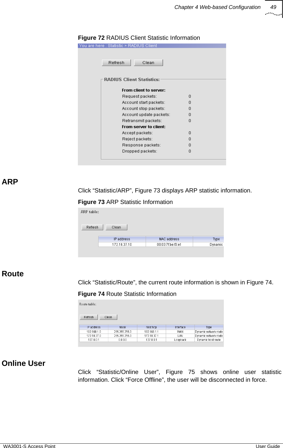
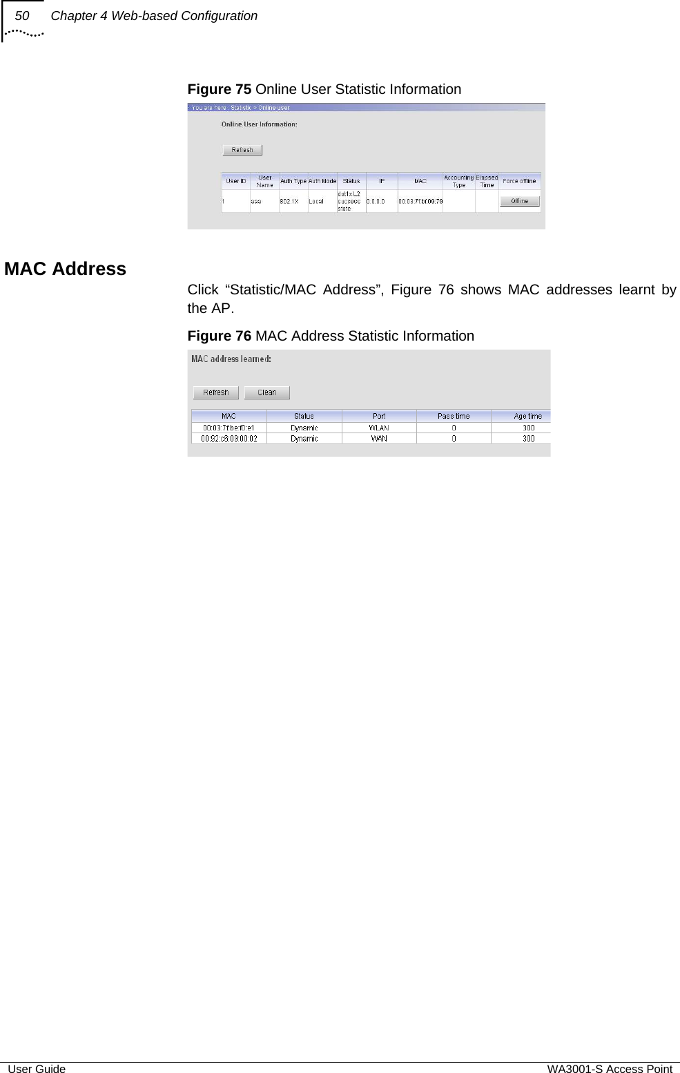
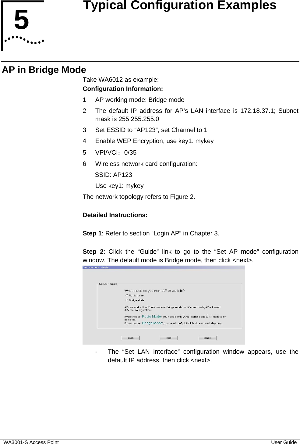
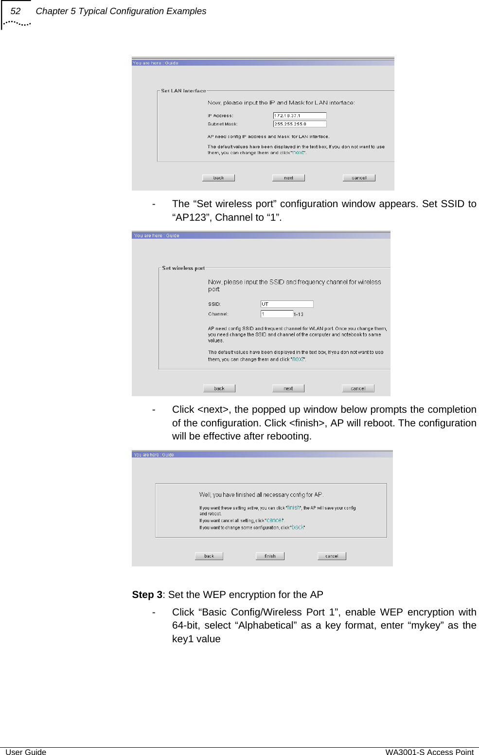
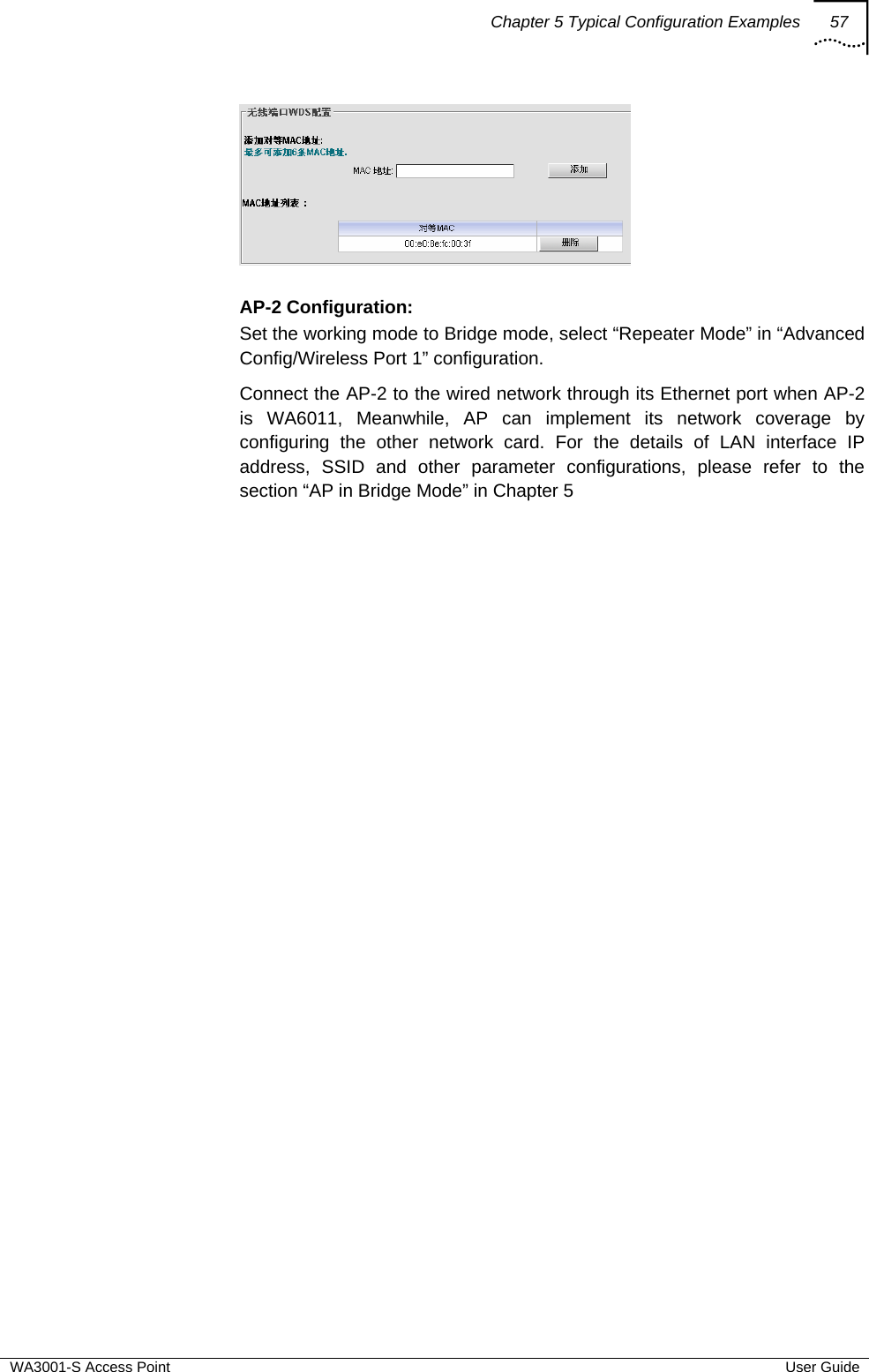
user manual
Contents
1.
user manual
2.
antenna installation guide
user manual
Navigation menu
Upload a User Manual
Namespaces
Wiki Guide
HTML
PDF
Info
Views
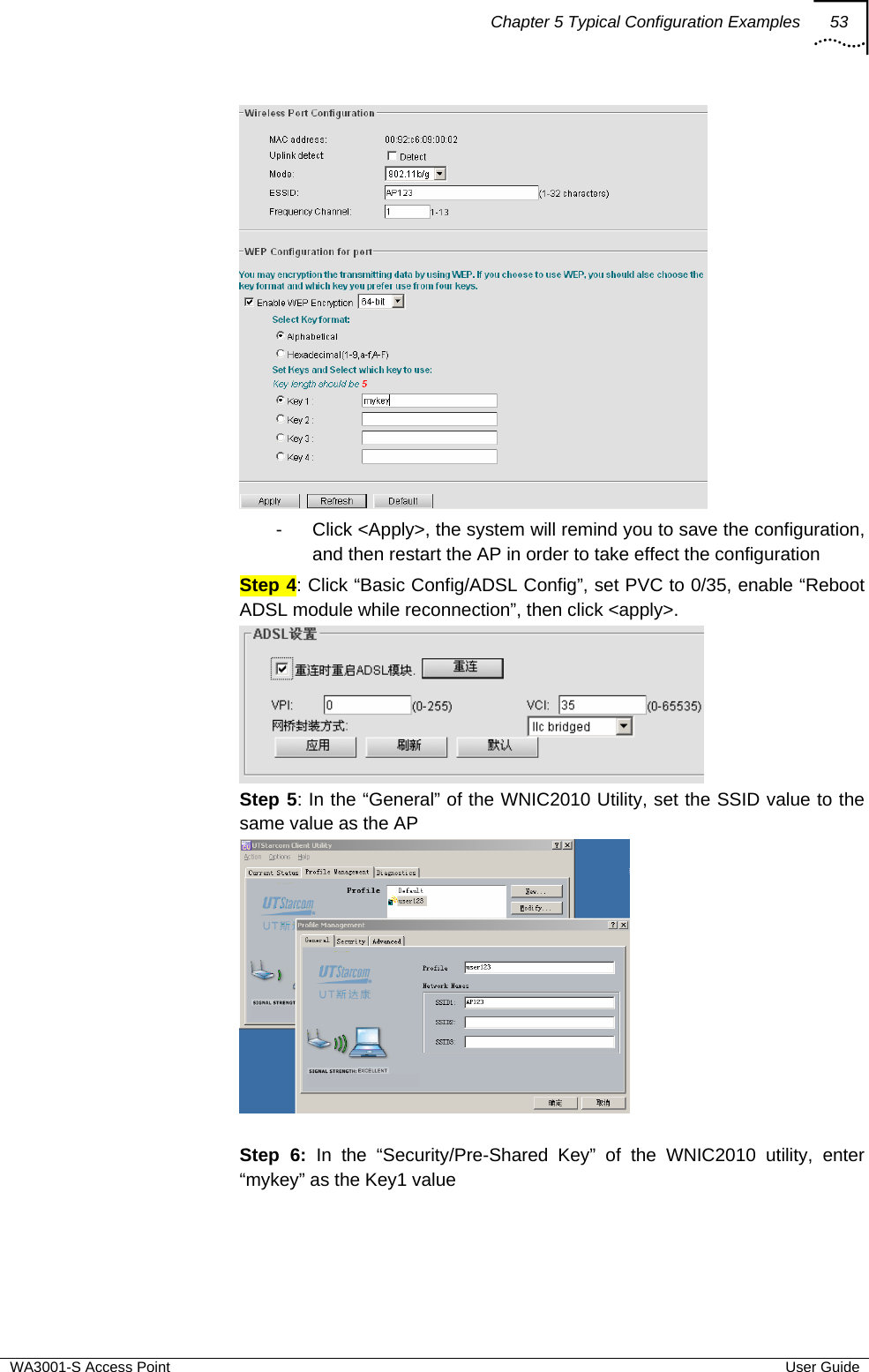
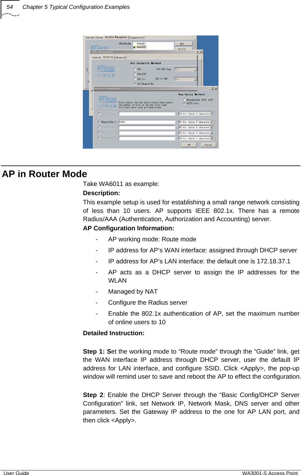
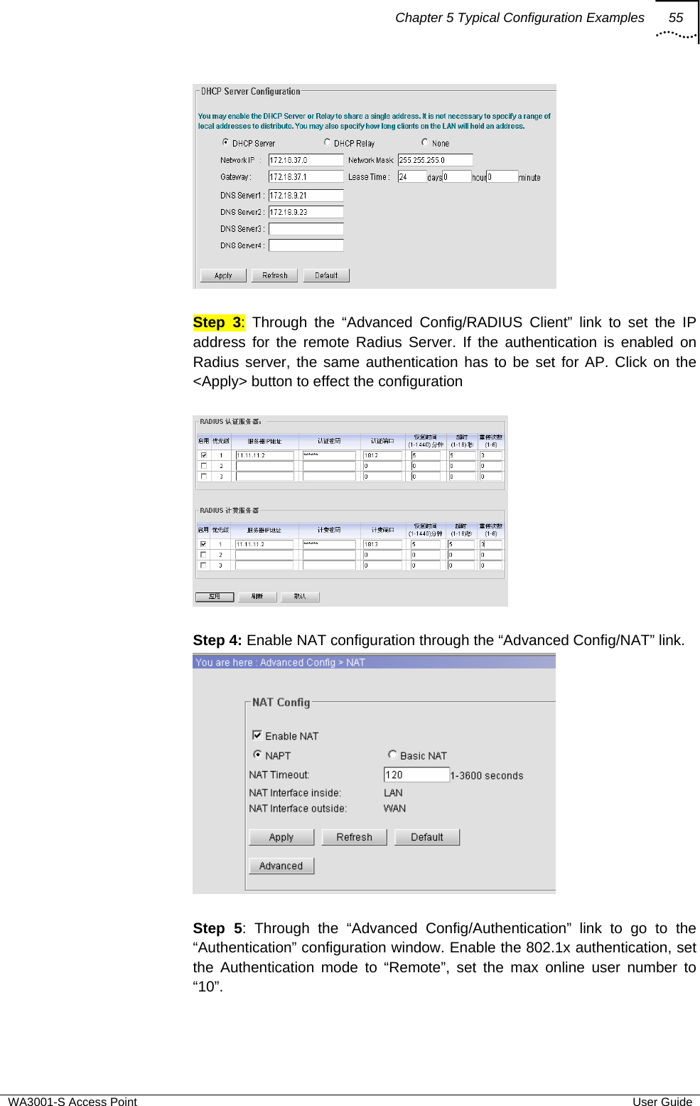
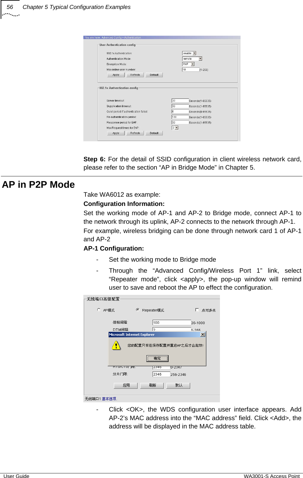
User Manual
Discussion / Help
Navigation
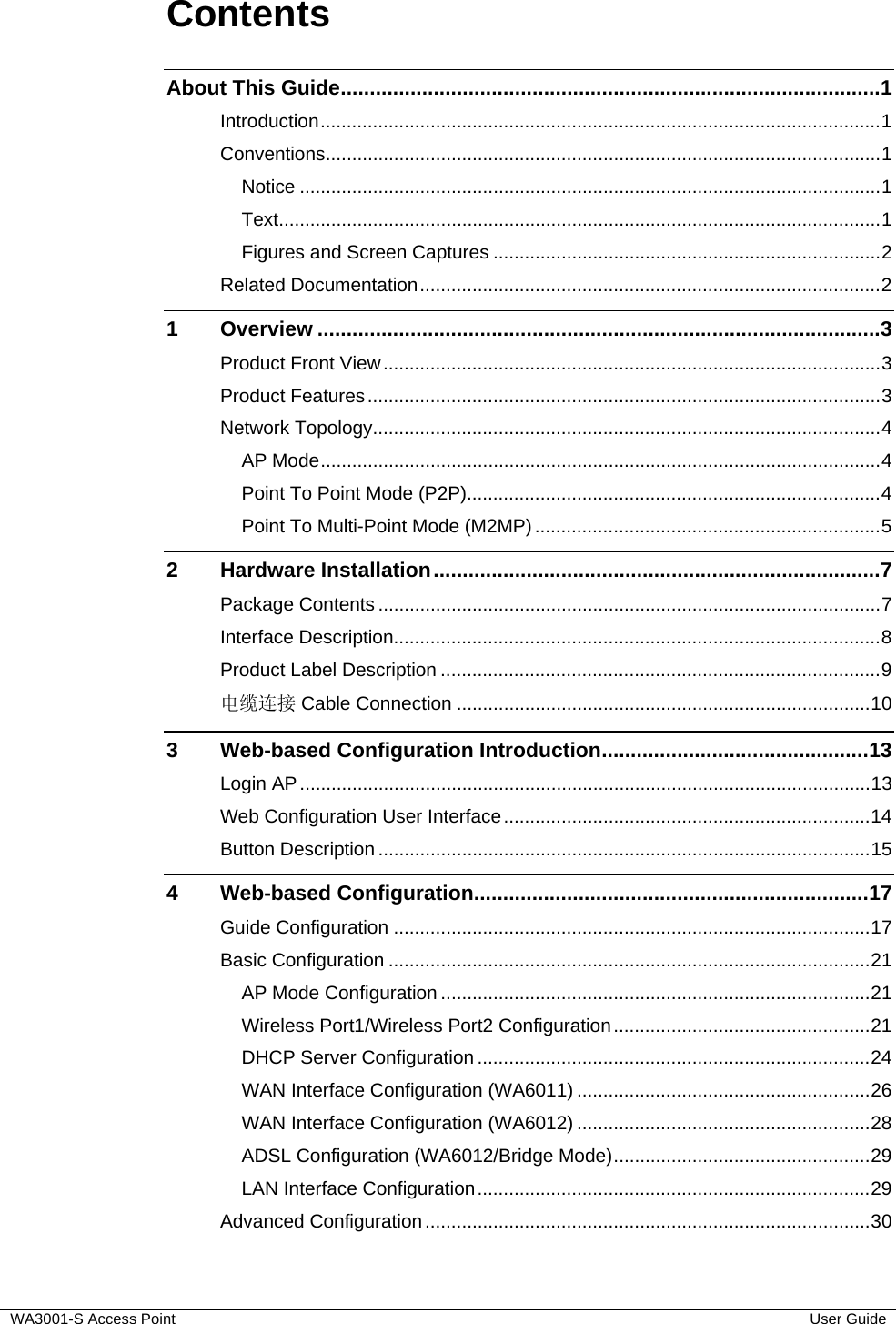
![2 About This Guide User Guide WA3001-S Access Point Convention Description Text represented by [Menu] and [Menu/Sub-menu] This typeface represents menus such as [File], and [File/New] Text represented by <Button> This typeface represents button on screen, function key on the keyboard and icon names for example, click <OK>. Text represented by Document Name This typeface represents documents for reference, for example, Netman 2020-based AN2000B-900 Installation Guide Text represented by # File format: This typeface represents files in Unix/Linux system flies. Figures and Screen Captures This guide provides figures and screen captures as example. These examples contain sample data which may vary from the actual data on an installed system. Related Documentation • WA6011/6012 Outdoor AP CLI Command Reference](https://usermanual.wiki/UTStarcom-Telecom/6011.user-manual/User-Guide-511617-Page-12.png)