UBS Axcera DT830A 300-Watt UHF Digital Transmitter User Manual TITLE PAGE DT830A
UBS-Axcera 300-Watt UHF Digital Transmitter TITLE PAGE DT830A
UserManual.wiki
>
UBS Axcera
>
DT830A User Manual
>
Users Manual DT830A
Contents
1.
Users Manual DM8 Modulator Tray
2.
Users Manual DT830A
Users Manual DT830A
Navigation menu
Upload a User Manual
Namespaces
Wiki Guide
HTML
PDF
Info
Views
User Manual
Discussion / Help
Navigation
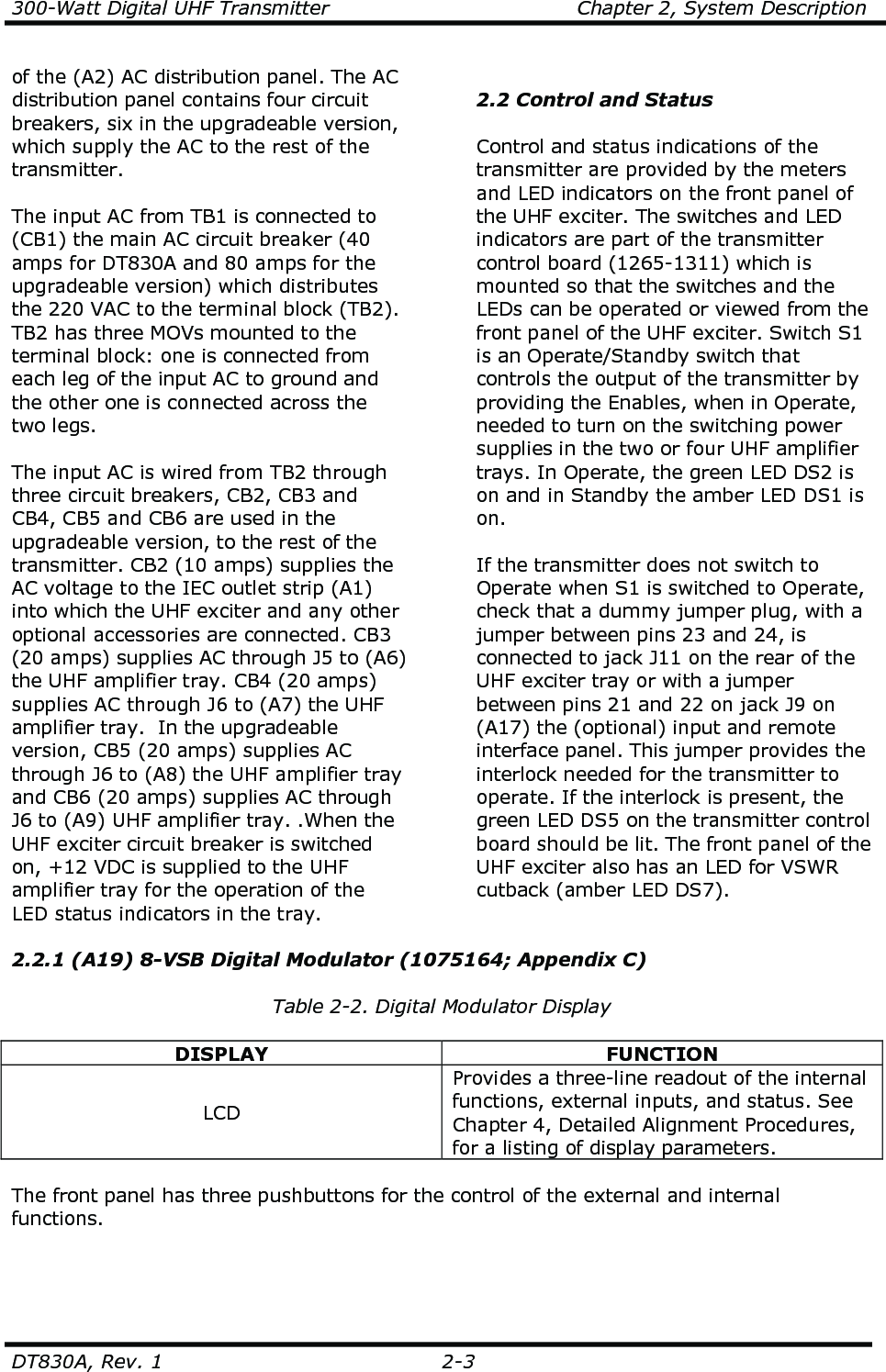
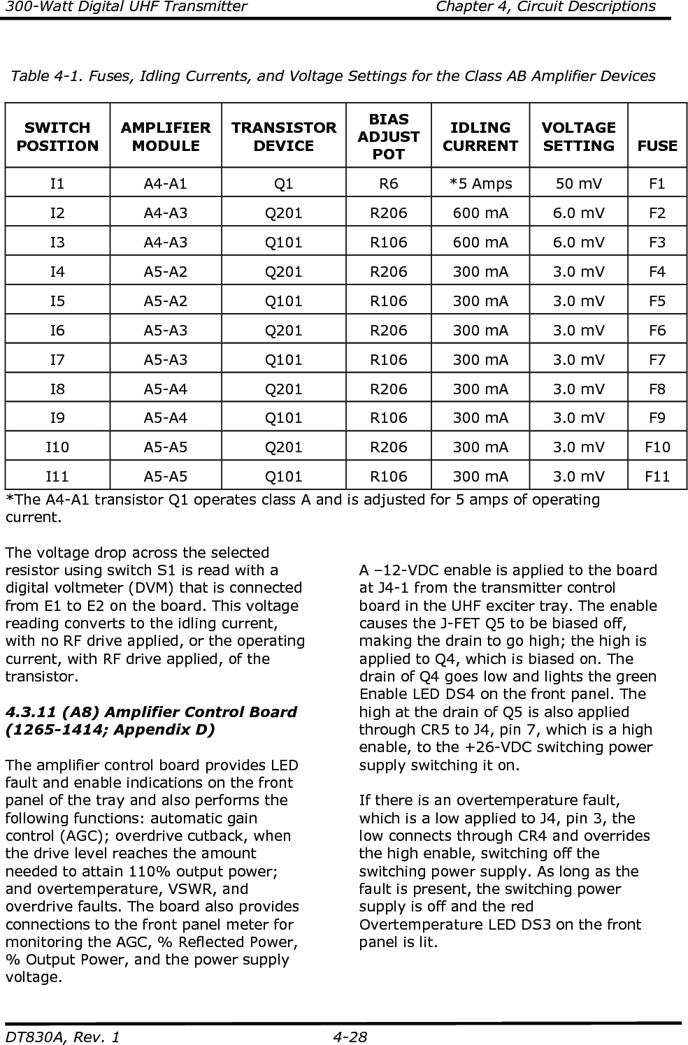
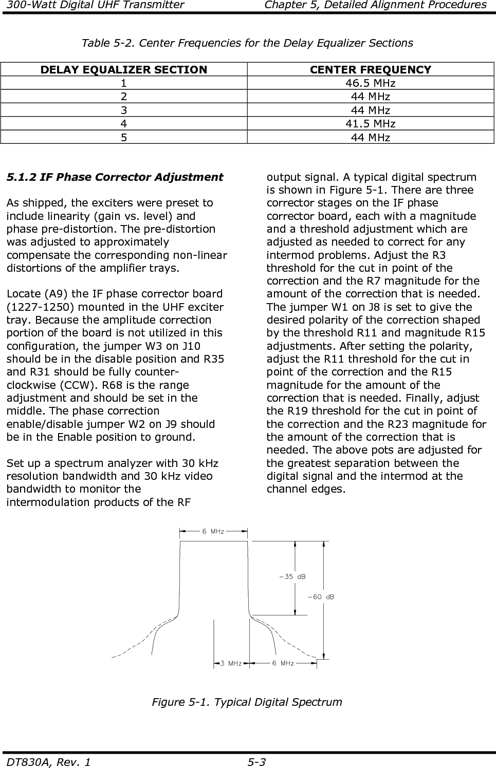
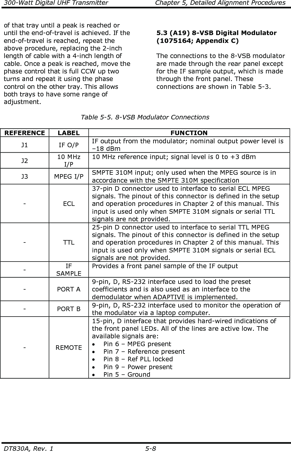
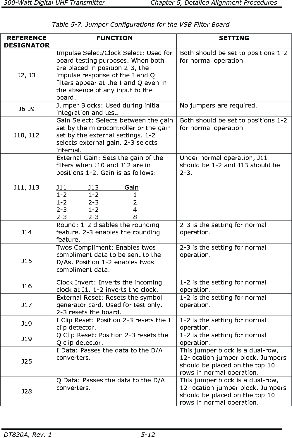
![300-Watt Digital UHF Transmitter Chapter 3, Installation and Setup Procedures DT830A, Rev. 1 3-5 Caution: Each UHF amplifier tray has a hardline coaxial cable connected to the bottom panel. The tray will not slide out unless this cable is first removed. To pull the tray out for test purposes, use the extender coaxial cable included in the installation material kit for connections from the tray to the output cable. Adjustments to the position of the trays may be necessary. To accomplish this, loosen the cabinet slide mounting bolts that hold the front of the slide to the mounting frame of the cabinet and move the tray up or down as needed to correct for the rubbing. The air intake to the transmitter is intended for room air only. The cabinet should be positioned with consideration given to adequate air intake and exhaust, the opening of the rear door, access to the trays (including sliding them out for testing), the main AC hookup, and the installation of the output transmission line. The cabinet should be grounded using copper strapping material and should also be permanently mounted to the floor of the site using the holes in the bottom of the cabinet. 3.3 Installation of the Cabinets and Trays Once the cabinet is in place and the trays are checked for damage, the main AC hookup is ready to be made. Caution: Before connecting the 230 VAC, make certain that all of the circuit breakers associated with the transmitter are switched off. The main AC input circuit to the transmitter should be a 40-amp, 80-amp for upgradeable version, 230-VAC line, using AWG 8 wire inside of a 1-1/4" conduit. The 230-VAC input connections (terminals 1 and 2 [230 VAC] and terminal 3 [chassis ground]) are made to terminal block TB1, which is part of (A2) the AC distribution panel near the rear door of the transmitter. Line 2 is the neutral for international systems using 220 VAC hot and neutral. The RF output at J2 of (A11) the coupler assembly, which is 7/8" rigid coax, should connect to the transmission line that is connected to the antenna system. The MPEG digital source input connects to J3, ECL, or TTL, depending on the configuration, at the rear panel of (A19) the modulator or J2 on (A12) the remote interface panel. Remote functions connect to the rear of (A4) the UHF exciter or to (A12) the input and remote interface panel mounted on the rear top of the transmitter. A plug is connected to jack J11 with pins 23 and 24 jumpered together on the UHF exciter or to jack J9 with pins 21 and 22 jumpered together on the (optional) remote interface panel. These are 37-pin, “D”-connectors that provide the interlock for the transmitter. Jacks J10 and J11 on the UHF exciter, and jacks J9 and J10 on the (optional) remote interface panel, are used to connect the remote control functions to the transmitter. This completes the unpacking and installation procedures for the DT830A Digital UHF Transmitter. Refer to the setup and operation procedures that follow before applying power to the transmitter. 3.4 Setup and Operation Procedures The transmitter should initially be turned on with the RF output of the bandpass filter/coupler assembly terminated into a dummy load of at least 500 watts. If a load is not available, check that the output of the coupler assembly is connected to the antenna. Switch on the main AC, UHF exciter, digital modulator, and the amplifier #1 and #2, amplifier #3 and #4 are used after upgrade, circuit breakers located on the AC distribution panel facing the rear](https://usermanual.wiki/UBS-Axcera/DT830A.Users-Manual-DT830A/User-Guide-1242667-Page-24.png)
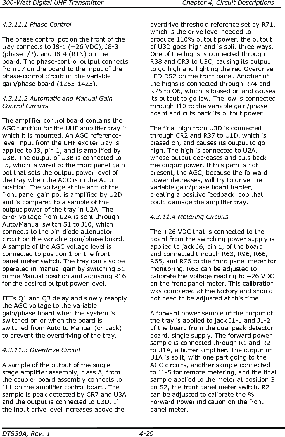
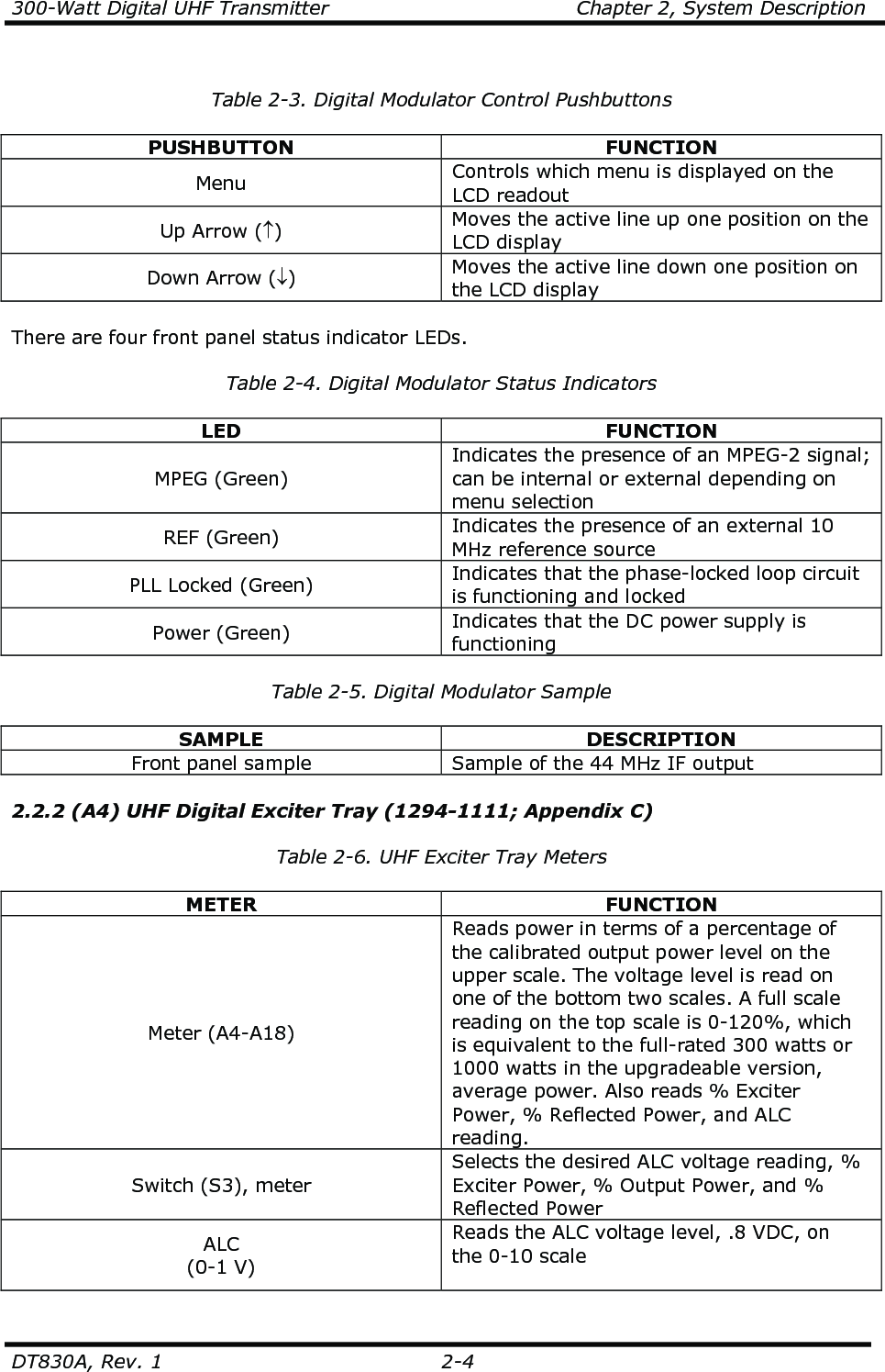
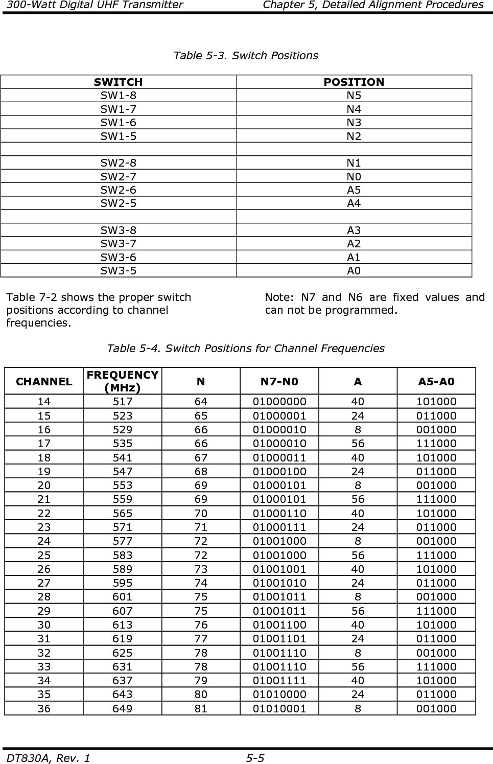
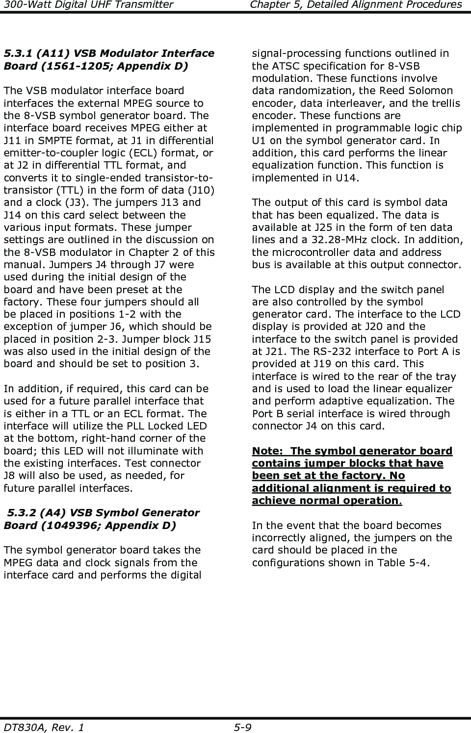
![300-Watt Digital UHF Transmitter Chapter 5, Detailed Alignment Procedures DT830A, Rev. 1 5-4 5.1.3 (A15-A1) UHF Generator Board (1565-1109) The (A15-A1) UHF generator board is mounted in (A15) the UHF generator enclosure. This procedure should be performed to align this board. In the Manual Adjust position, W1 on J4 on (A13) the PLL board (1286-1104) must be moved for –2.5 volts. Connect J1, the sample output of the section of the UHF generator board, to a spectrum analyzer, tuned to the crystal frequency, and peak tuning capacitors C6 and C18 for maximum output. Also tune L2 and L4 for maximum output. The output level should be about +5 dBm. The channel oscillator should maintain an oven temperature of 50° C. If a spectrum analyzer is not available, connect a digital voltmeter (DVM) to TP1 on the UHF generator board. Tune capacitor C32 for maximum voltage at TP1. Connect J2, the sample output of the channel oscillator, to a suitable counter and tune C11, the coarse adjust, to the crystal frequency. The fine frequency is controlled by the external PLL circuit when in the Auto mode. Caution: Do not repeak C32. This can change the output level. Connect a spectrum analyzer to J2, the output jack of the board. Tune C32, C34, C38, C40, C44, and C46 for maximum output. Re-adjust all of the capacitors to minimize the seventh and the ninth harmonics of the channel oscillator frequency. They should be down at least -30 dB without affecting the output of the UHF generator board. If a spectrum analyzer is not available, a DC voltmeter can be used. When a voltmeter is used, the harmonic frequencies must be minimized to prevent interference with other channels. While monitoring each test point with a DC voltmeter, maximize each test point by tuning the broadband multipliers in the following sequence: • Monitor TP1 with a DVM and tune C32 for maximum (typical 0.6 VDC). • Monitor TP2 and tune C34 and C38 for maximum (typical 1.2 VDC). • Monitor TP3 and tune C40 and C44 for maximum (typical 2.0 VDC). • Monitor TP4 and tune C46 for maximum. • Repeak C40 and C38 while monitoring TP4 (typical 3.5 VDC). • The typical output level is +15 dBm. 5.1.4 (A14-A1) 10-MHz Reference Generator Board (1519-1126) Monitor J1 with a spectrum analyzer. Adjust C12 for a maximum 10-MHz signal. Attach a frequency counter. Tune C3 for a coarse frequency adjustment close to 10 MHz and C2 for exactly 10 MHz. Re-adjust C12 for peak signal amplitude at J1 using the spectrum analyzer. Adjust R15 to maintain a constant crystal temperature of 50° C. 5.1.5 (A13) PLL Board (1286-1104) With W1 on J4-2 and J4-3, adjust R12 for –2.5 volts on J6-2. Adjust C11 on the (A8-A1) UHF generator board (1565-1109) for the correct channel oscillator frequency. Monitor J10 on the board. Install jumper W1 between J4-1 and J4-2. With switches SW1, SW2, and SW3 in the positions shown in Table 7-1 (refer to the PLL board schematic [1286-3104]), the PLL Unlock LED should go out.](https://usermanual.wiki/UBS-Axcera/DT830A.Users-Manual-DT830A/User-Guide-1242667-Page-62.png)
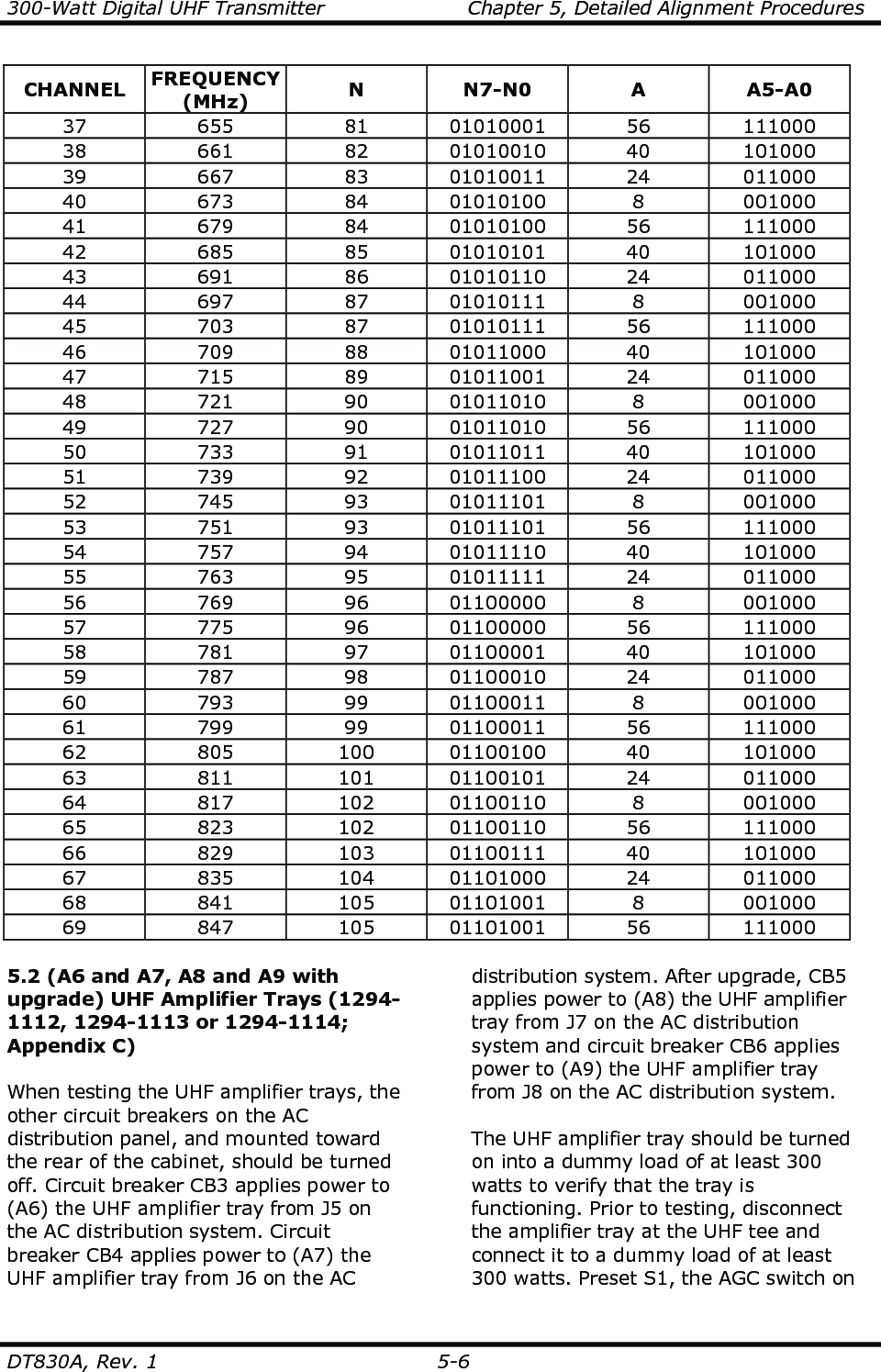
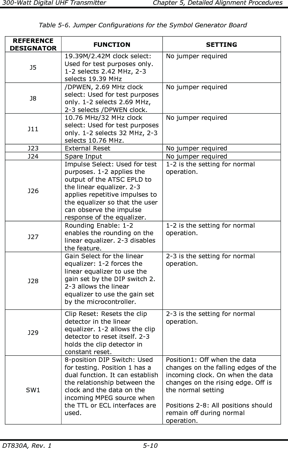


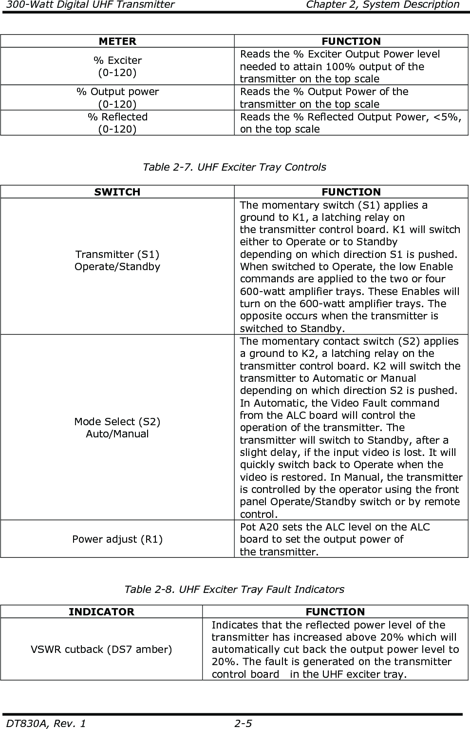
![300-Watt Digital UHF Transmitter Appendix D, Subassembly Drawings DT830A, Rev. 1 D-1 UHF Filter Schematic........................................................................................ 1007-3101 +12-Volt, 2-Amp Power Supply Board Schematic........................................................................................ 1128-3504 IF Phase Corrector Board Schematic........................................................................................ 1227-3250 1-Watt Amplifier Board Schematic........................................................................................ 1227-3303 4-Way Splitter Board Schematic........................................................................................ 1227-3312 Coupler Board Assembly Schematic........................................................................................ 1227-3316 Dual Peak Detector Board, Single Supply Schematic........................................................................................ 1227-3333 ALC Board Schematic........................................................................................ 1265-3305 Visual/Aural Metering Board Schematic........................................................................................ 1265-3309 UHF Upconverter Board Schematic........................................................................................ 1265-3310 Transmitter Control Board Schematic........................................................................................ 1265-3311 +12V(4A)/-12V(1A) Power Supply Board Schematic........................................................................................ 1265-3312 Dual Stage Amplifier Assembly, Mid Band, Class AB (Made from a Generic Dual Stage Amplifier Board, Class AB [1265-1404]) Schematic........................................................................................ 1265-3411 Amplifier Protection Board Schematic........................................................................................ 1265-3412 Dual Stage Amplifier Assembly, Low Band, Class AB (Made from a Generic Dual Stage Amplifier Board, Class AB [1265-1404]) Schematic........................................................................................ 1265-3413 Amplifier Control Board Schematic........................................................................................ 1265-3414 (Made from a Generic Single Stage Amplifier Board, Class A [1265-1415]) Schematic........................................................................................ 1265-3416](https://usermanual.wiki/UBS-Axcera/DT830A.Users-Manual-DT830A/User-Guide-1242667-Page-83.png)
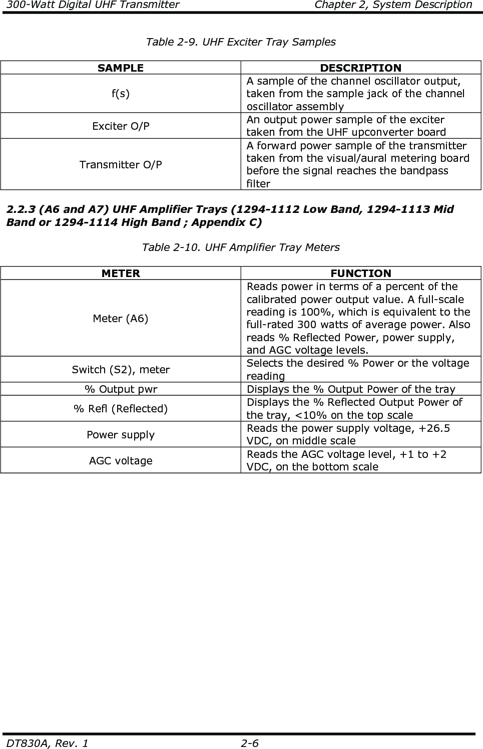
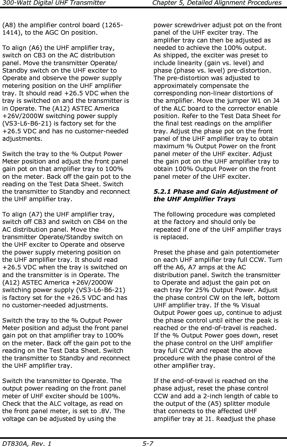
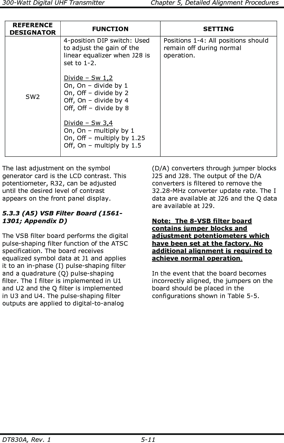
![300-Watt Digital UHF Transmitter Appendix D, Subassembly Drawings DT830A, Rev. 1 D-2 Single Stage Amplifier Assembly, High Band, Class A (Made from a Generic Single Stage Amplifier Board, Class A [1265-1415]) Schematic........................................................................................ 1265-3417 Single Stage Amplifier Assembly, Low Band, Class A (Made from a Generic Single Stage Amplifier Board, Class A [1265-1415]) Schematic........................................................................................ 1265-3418 Dual Stage Amplifier Assembly, High Band, Class AB (Made from a Generic Dual Stage Amplifier Board, Class AB [1265-1404]) Schematic........................................................................................ 1265-3420 Variable Gain/Phase Board Schematic........................................................................................ 1265-3425 Dual Stage Amplifier Assembly, Low Band, Class AB (Made from a Generic Dual Stage Amplifier Board, Class AB [1265-1404]) Schematic........................................................................................ 1265-3439 Dual Stage Amplifier Assembly, Mid Band, Class AB (Made from a Generic Dual Stage Amplifier Board, Class AB [1265-1404]) Schematic........................................................................................ 1265-3440 Dual Stage Amplifier Assembly, High Band, Class AB (Made from a Generic Dual Stage Amplifier Board, Class AB [1265-1404]) Schematic........................................................................................ 1265-3441 PLL Board Schematic........................................................................................ 1286-3104 10-MHz Reference Generator Board Schematic........................................................................................ 1519-3126 Vector Modulator Board Schematic........................................................................................ 1520-3107 Dual Peak Detector Board, SMT Schematic........................................................................................ 1555-3270 Switchboard Schematic........................................................................................ 1561-3202 Local Oscillator Board Schematic........................................................................................ 1561-3203](https://usermanual.wiki/UBS-Axcera/DT830A.Users-Manual-DT830A/User-Guide-1242667-Page-84.png)