Tyco Safety Sensormatic IDRDR2 RFID READER User Manual USERS MANUAL
Tyco Safety Products/Sensormatic RFID READER USERS MANUAL
UserManual.wiki
>
Tyco Safety Sensormatic
>
IDRDR2 User Manual
USERS MANUAL
Navigation menu
Upload a User Manual
Namespaces
Wiki Guide
HTML
PDF
Info
Views
User Manual
Discussion / Help
Navigation
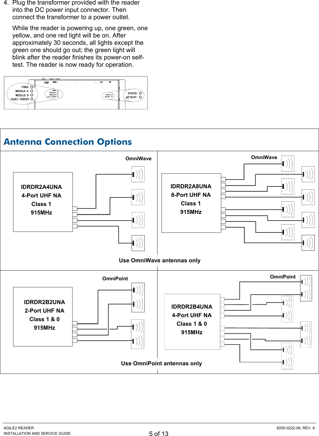
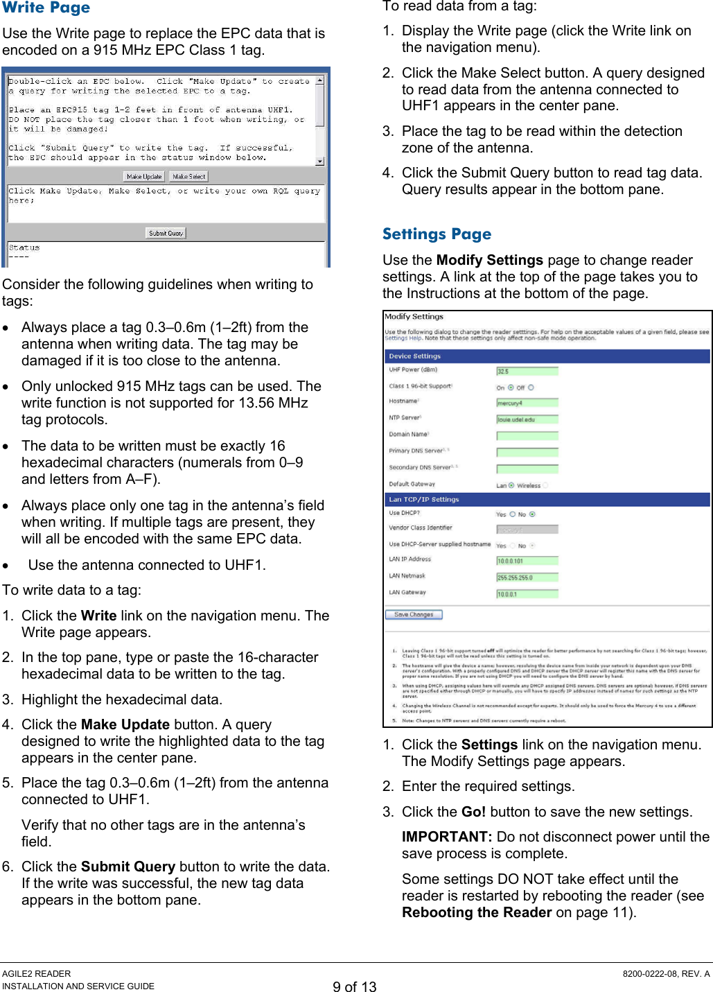
![AGILE2 READER 8200-0222-08, REV. A INSTALLATION AND SERVICE GUIDE 4 of 13 Reader Installation The following parts are provided with the reader: Part Qty. Part Number Multi-frequency RFID Reader 1 0101-0092-XX Power Supply 1 5605-0014-01 Installation and Service Guide 1 8200-0222-08 Regulatory Information for the User 1 8200-0222-04 Query Protocol Reference Guide 1 8200-0222-09 Anchor, Plastic, 10-12, 1"L, w/screw 2 2880-0098-01 IMPORTANT: Be sure the user receives Agile2 Reader Regulatory Information for the User, 8200-0222-16. Install the Reader You can place the reader on a shelf or mount it to a wall. To mount the reader on a wall: 1. Hold the reader in its mounting location and mark the position of the mounting screws (2). R-1 R-2 T-1 T-2T/R -1 T/R-2 T/R-3 T/R -4R-3 R-4 T-3 T-4T/R -5 T/R -6 T/R -7 T/R-8 2. Drill holes for the screws and install wall anchors if required. If wall anchors are required, use a 6.3mm (1/4in) drill bit. 3. Insert the screws and tighten until almost flush with the wall. 4. Slip the reader over the screws and slide down to lock the screws in the keyhole openings. 5. Tighten the screws. Install the Antennas The antennas can be mounted directly to a variety of surfaces. Follow the installation instructions provided with the antennas. Connect the Reader A = RJ-45 Ethernet port C = RS-232 B = Safe Mode button D = DC power input One to eight antennas can be connected to the reader, depending on the type of cards installed. Silk-screen markings on the reader identify the type of cards installed. Dual-element OmniPoint antennas are connected to 2-port cards Single-element OmniWave antennas are connected to 4-port cards. 1. Connect required UHF antennas to the ports on the reader (see Antenna Connection Options on page 5). IMPORTANT: Connect antennas to the ports before applying power to the reader. Any port not having an antenna connected to it will be disabled when the reader is powered on. 2. Verify that all antennas are securely connected. 3. Connect the reader to the network by plugging an Ethernet cable into the Ethernet port. or Connect the reader to a PC (personal computer) by plugging a crossover Ethernet cable into the Ethernet port. [If DHCP is to be used, then the network must be connected before powering up the reader.] Mounting holes AC BD4-Port cards 2-Port cards](https://usermanual.wiki/Tyco-Safety-Sensormatic/IDRDR2/User-Guide-473439-Page-4.png)