Tyco Safety Sensormatic DMS915 Digital Microwave System anti-theft equipment User Manual 8k039502b
Tyco Safety Products/Sensormatic Digital Microwave System anti-theft equipment 8k039502b
UserManual.wiki
>
Tyco Safety Sensormatic
>
DMS915 User Manual
>
Amended Manual
Contents
1.
installation and setup documentation
2.
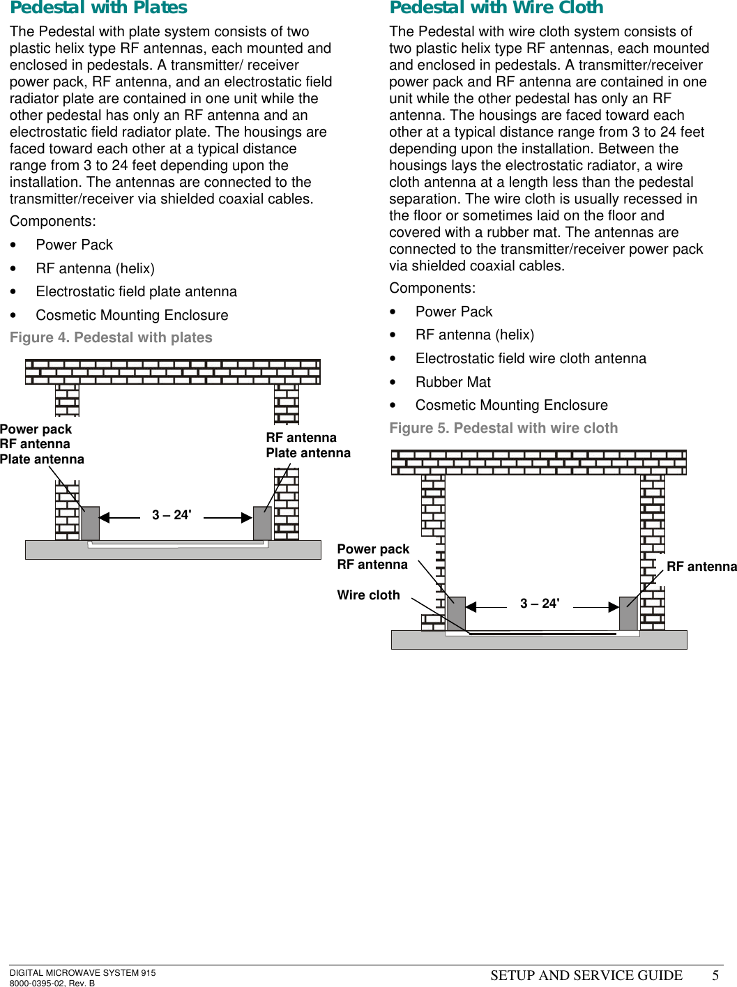
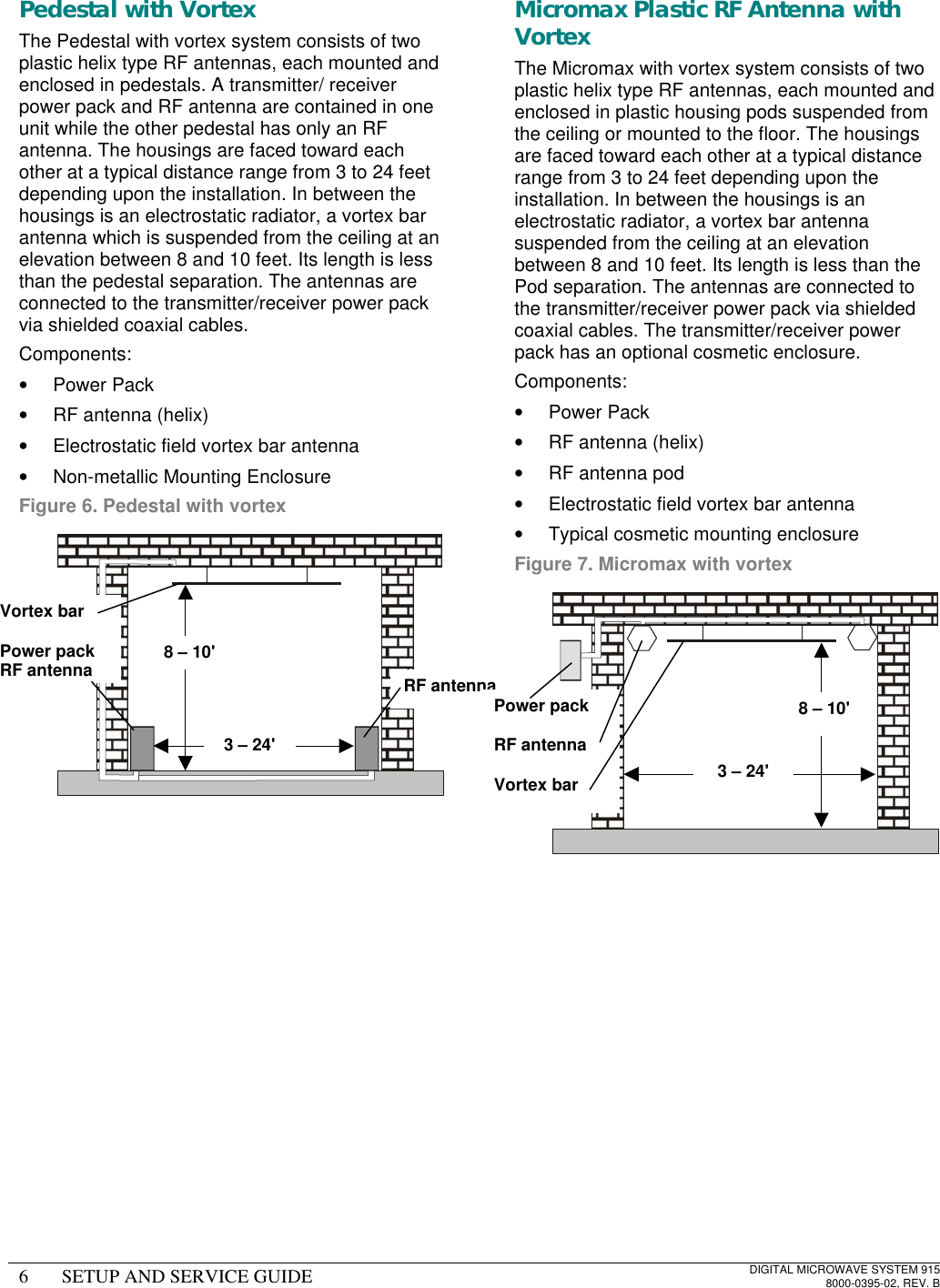
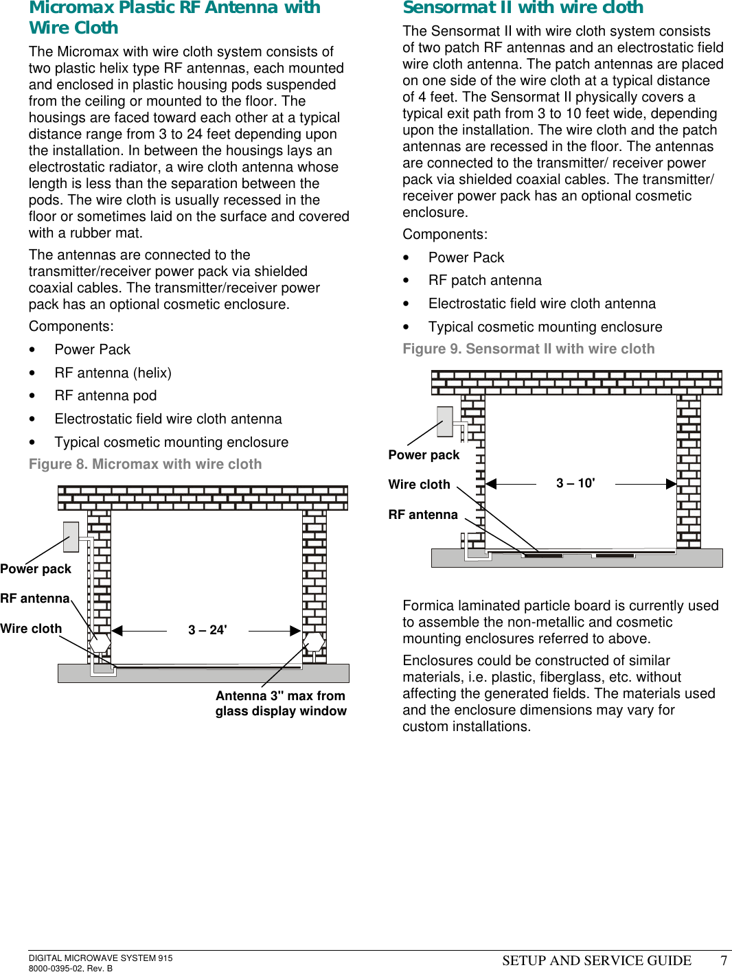
Set up and Installation Guide
3.
Amended Manual
Amended Manual
Navigation menu
Upload a User Manual
Namespaces
Wiki Guide
HTML
PDF
Info
Views
User Manual
Discussion / Help
Navigation