Trimble 55800 Bluetooth Device User Manual SPSx50 ModularGPSRcvr UserGuide
Trimble Navigation Ltd Bluetooth Device SPSx50 ModularGPSRcvr UserGuide
Trimble >
Contents
- 1. Users Manual Addendum
- 2. User Manual 1
- 3. User Manual 2
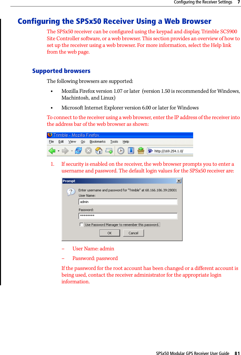
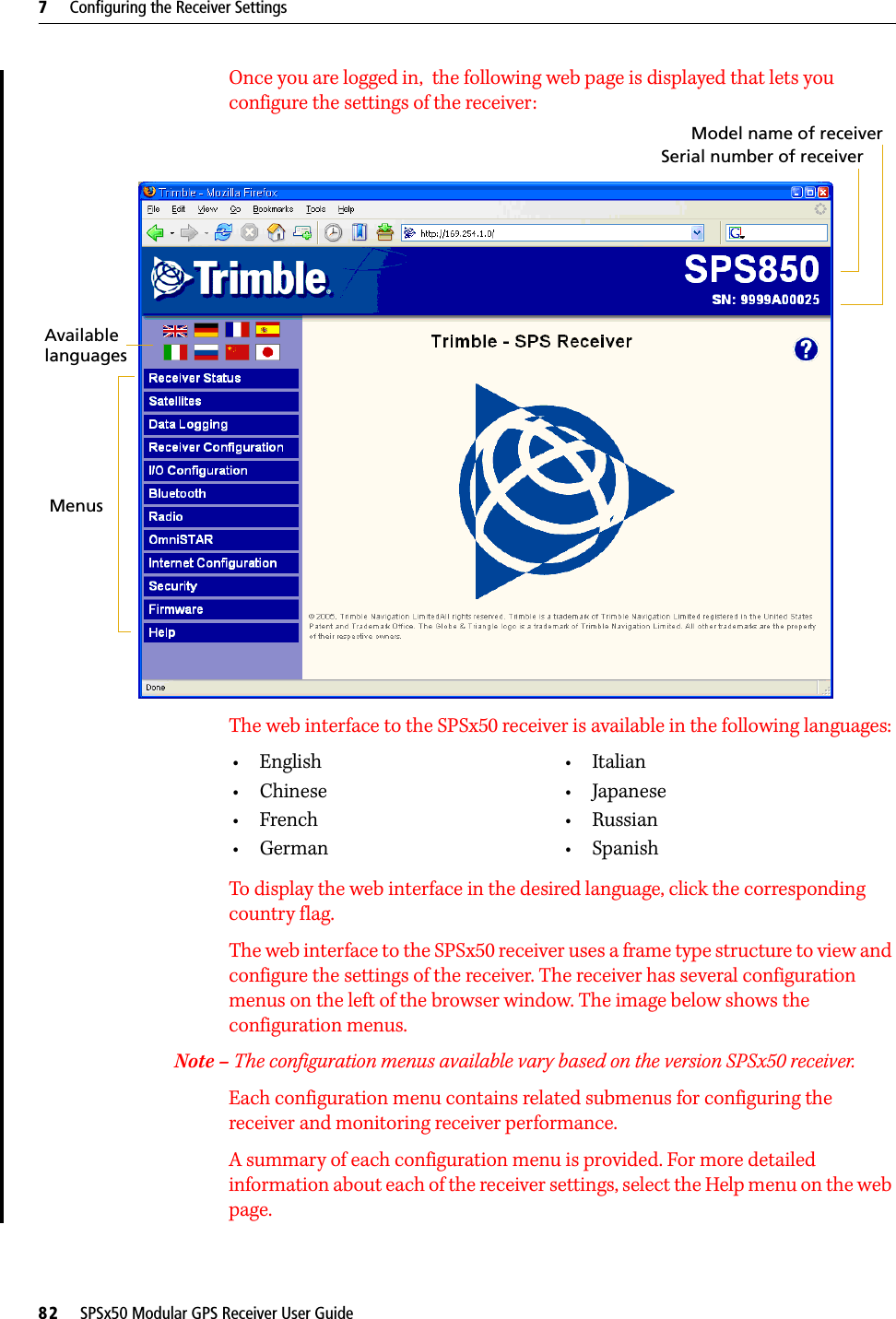
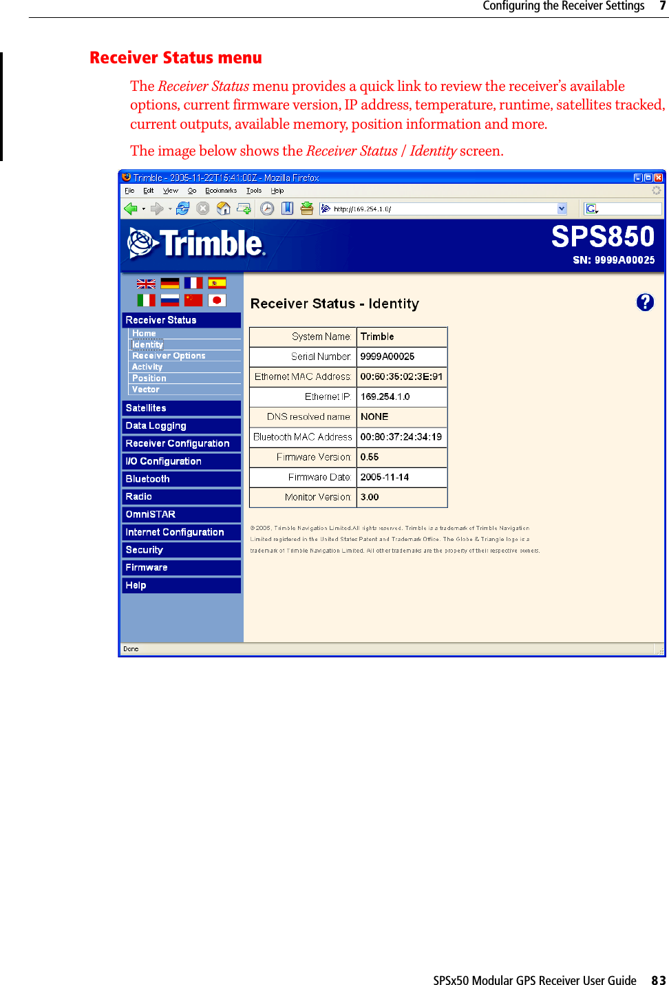
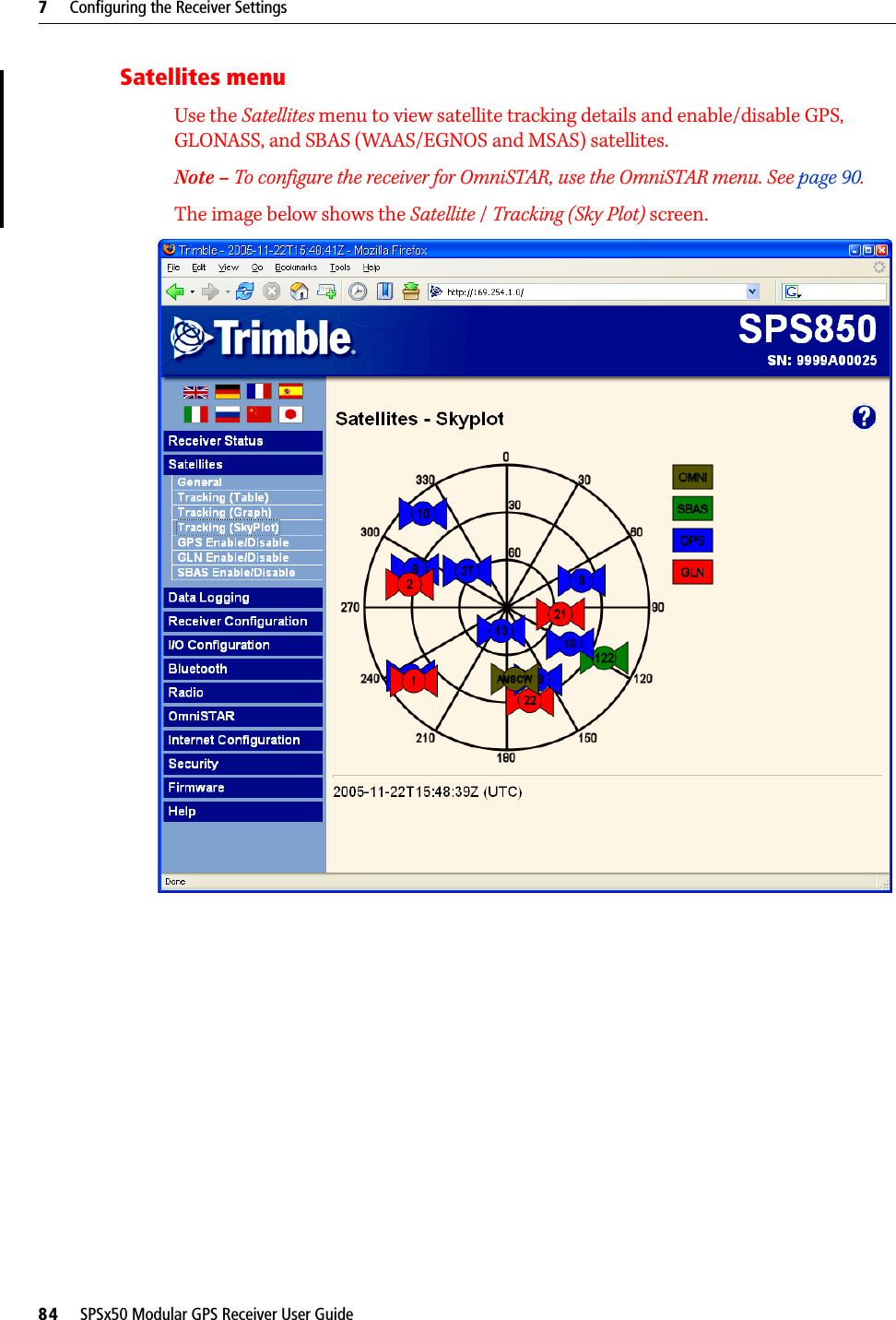
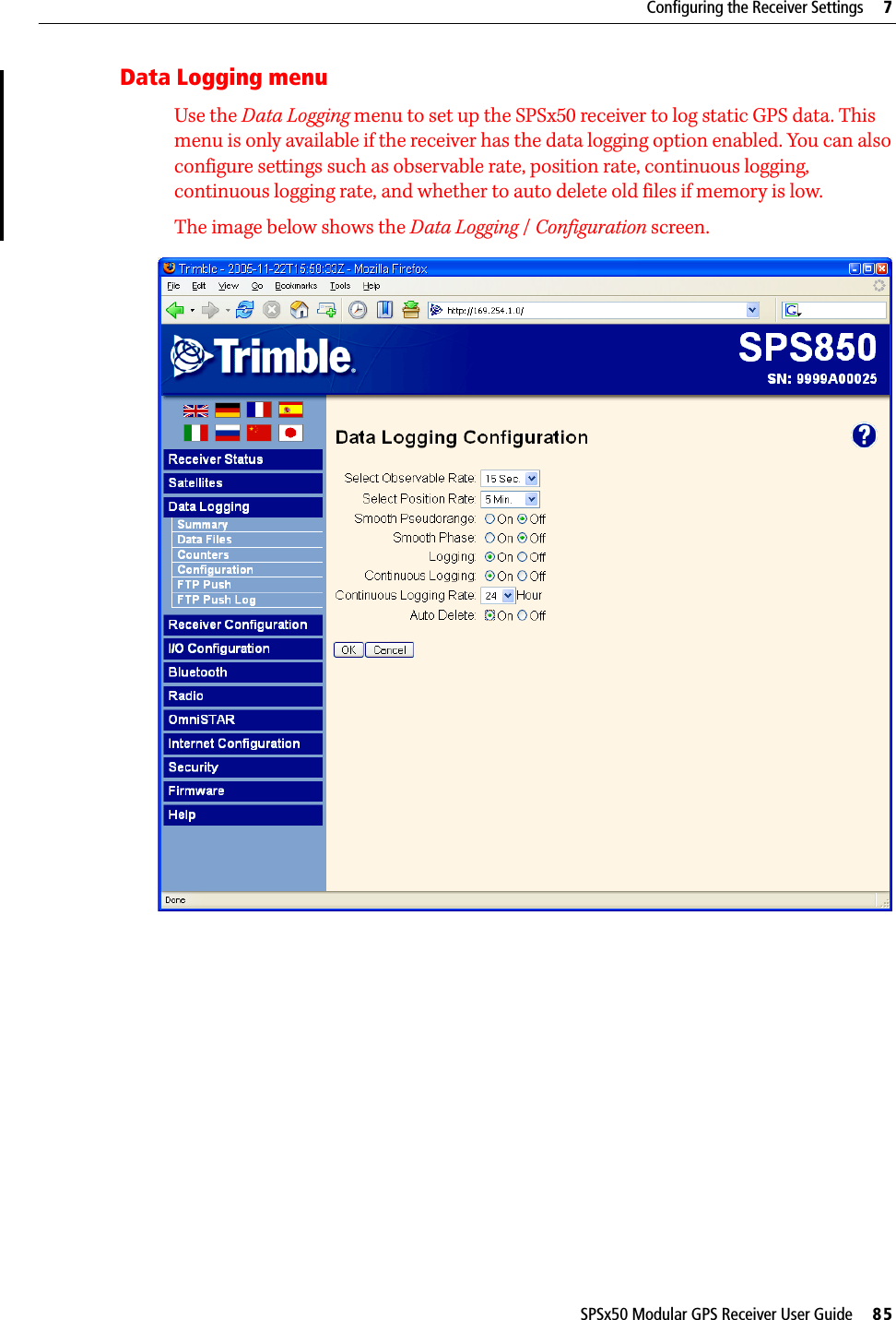
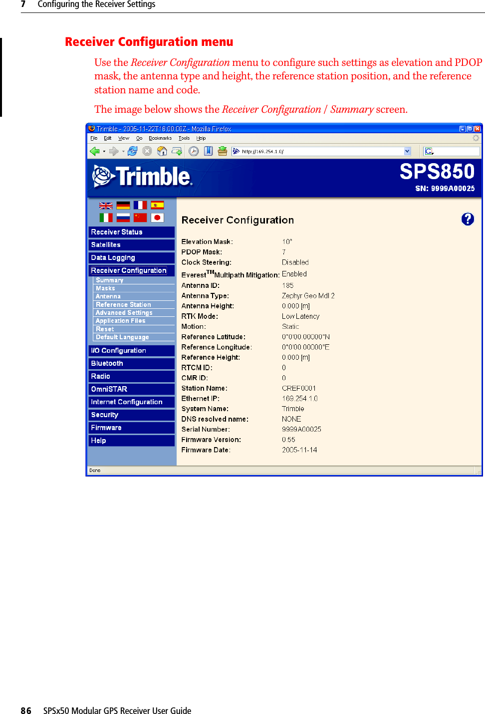
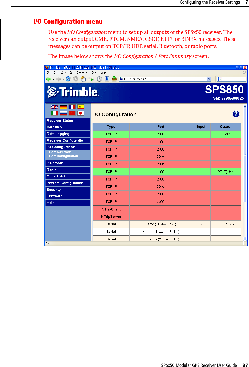
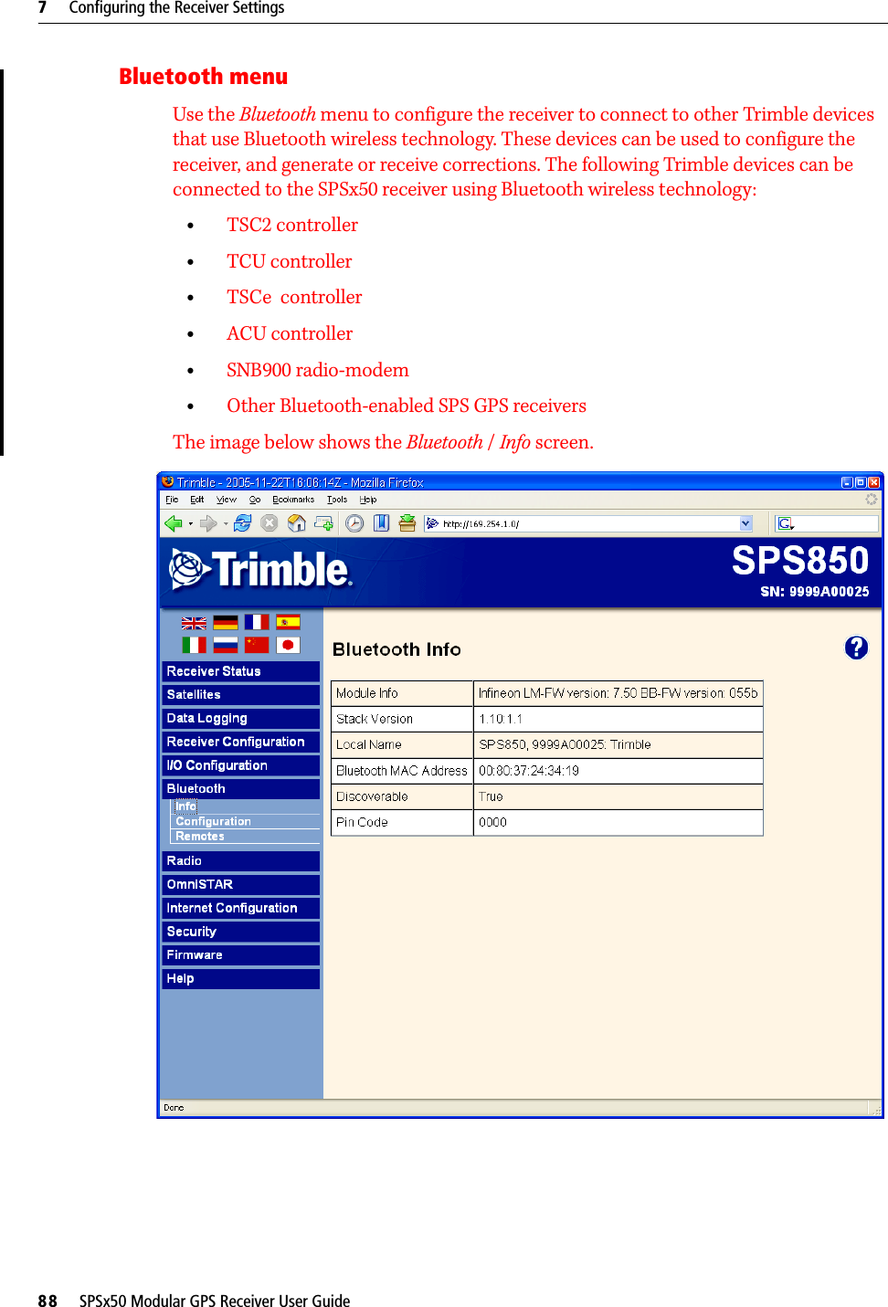
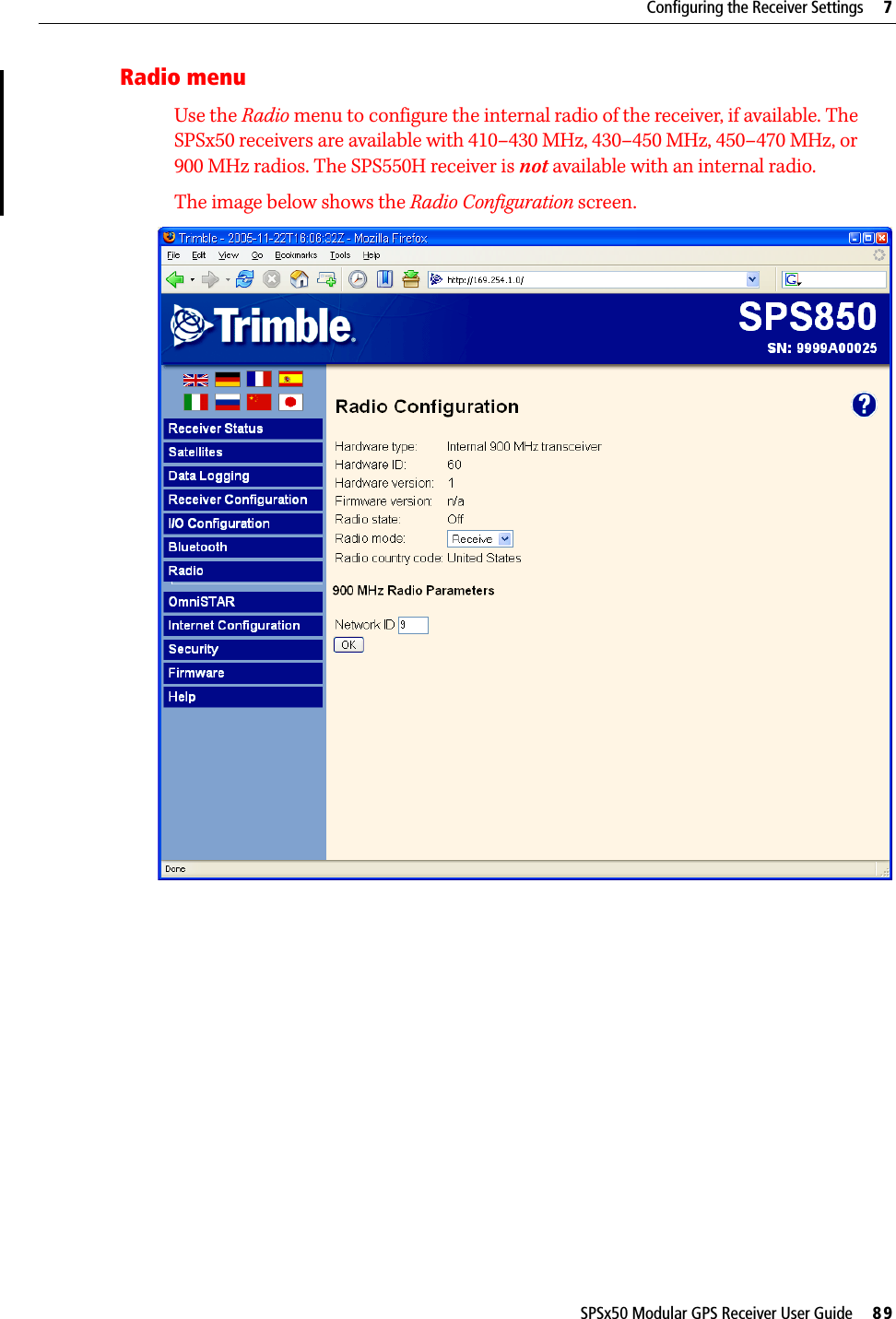
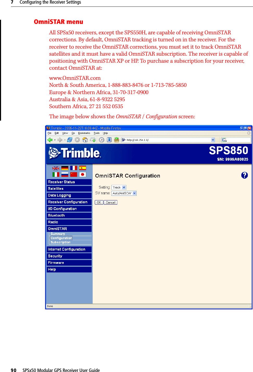
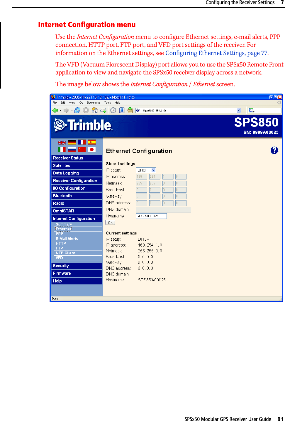
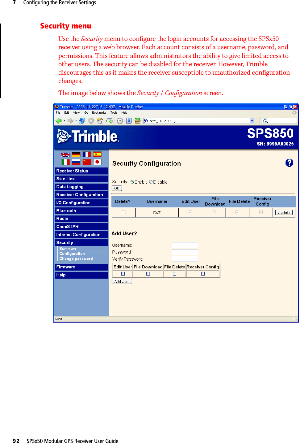
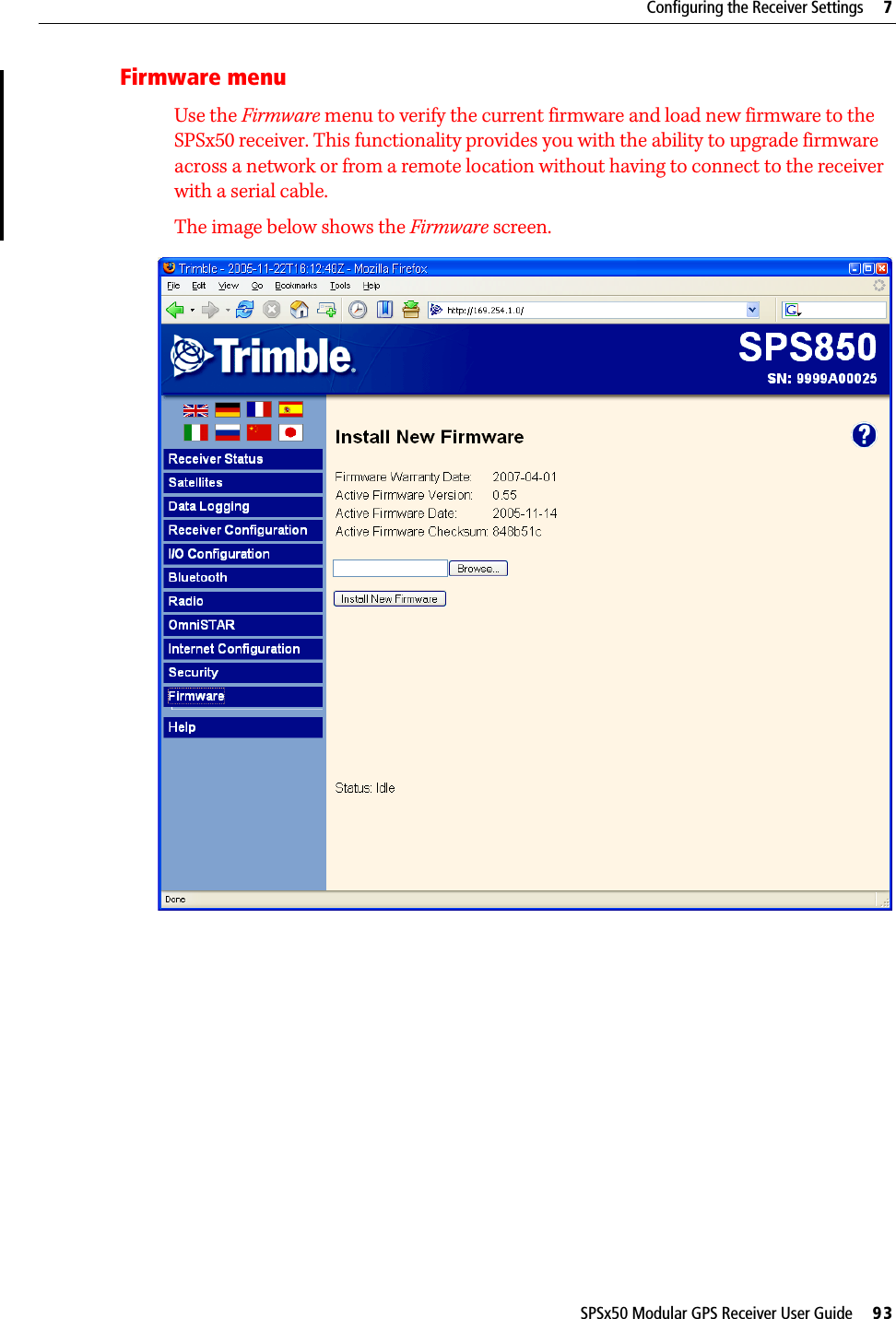
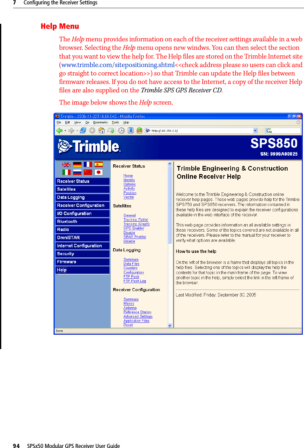
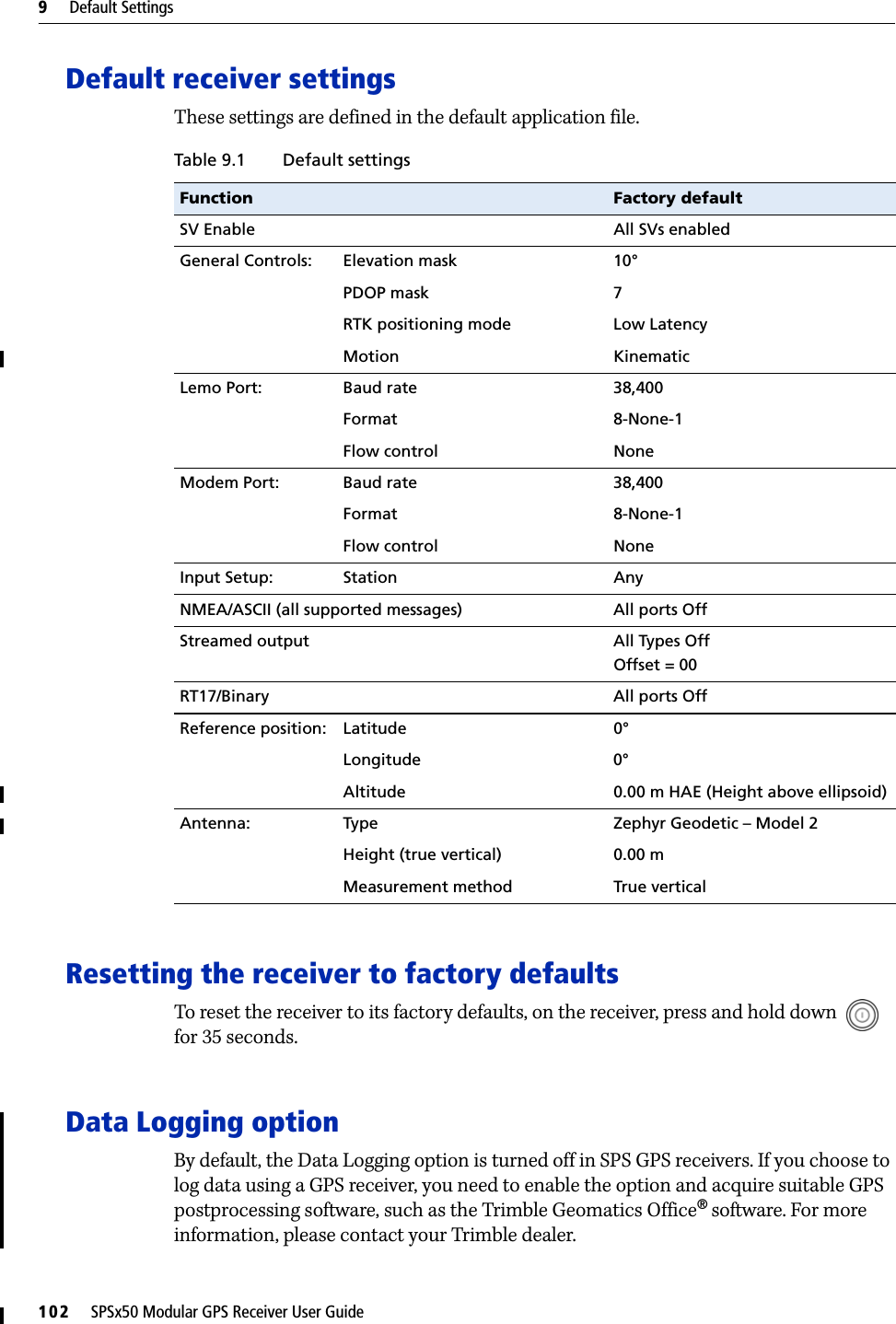
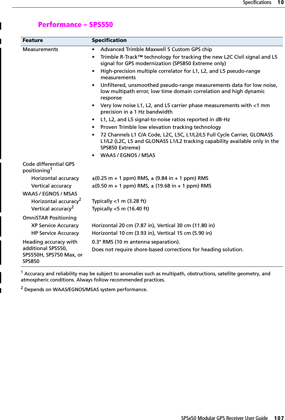
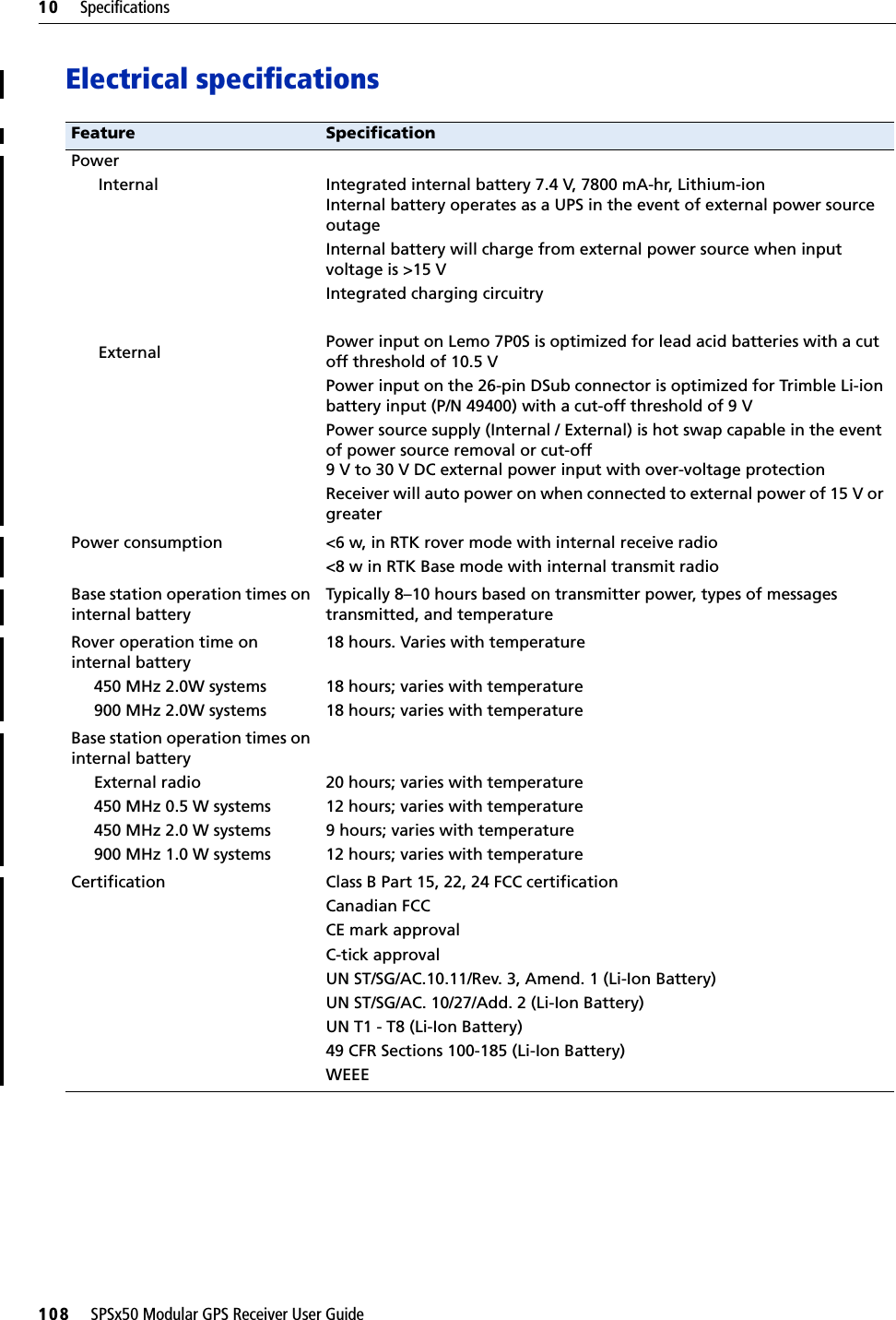
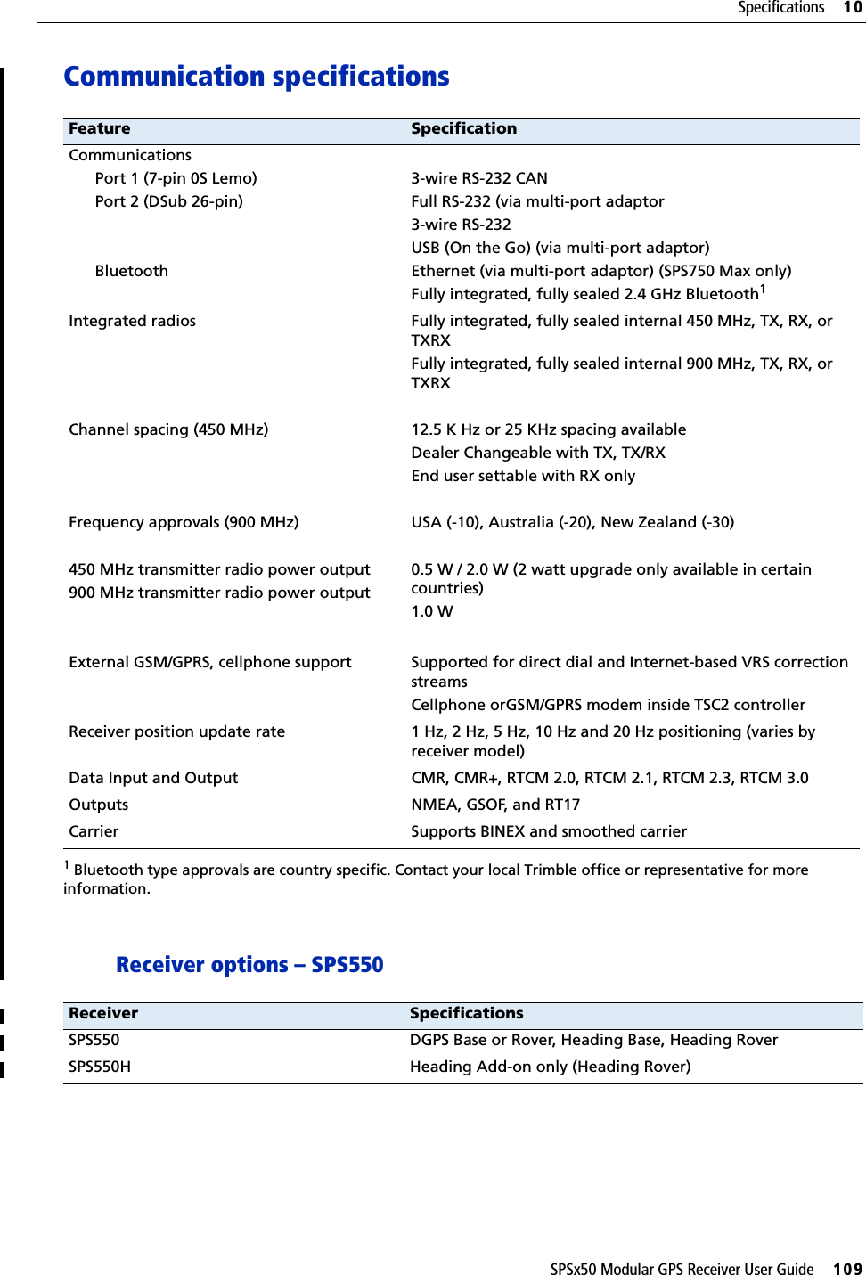
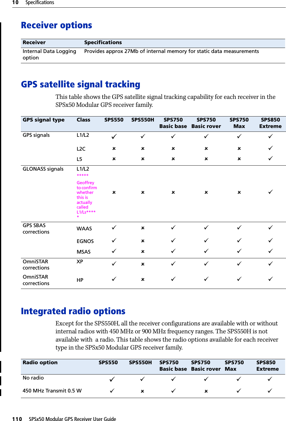
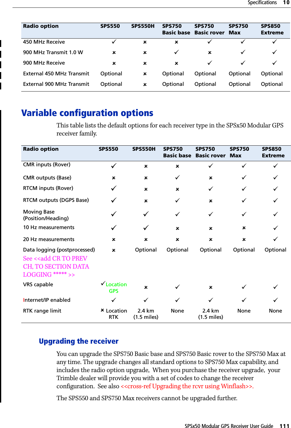
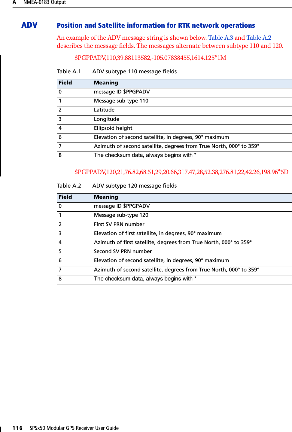
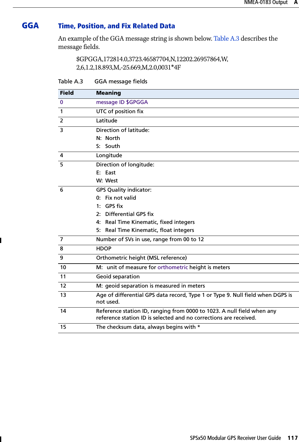
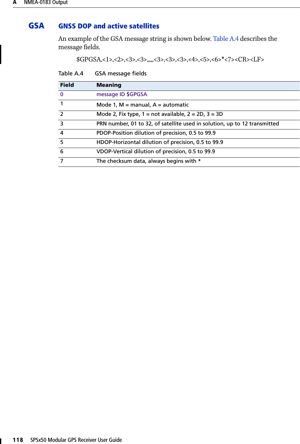
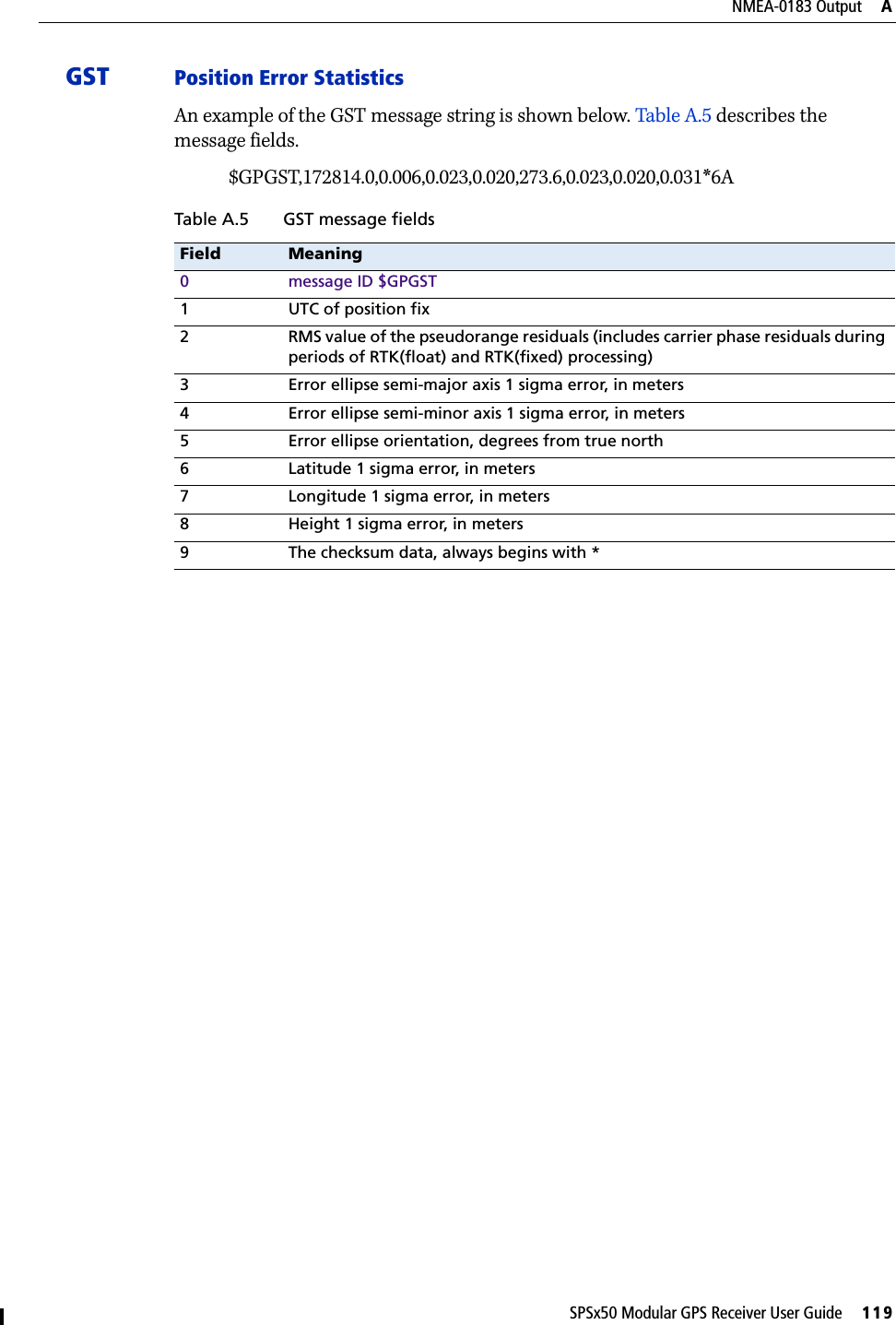
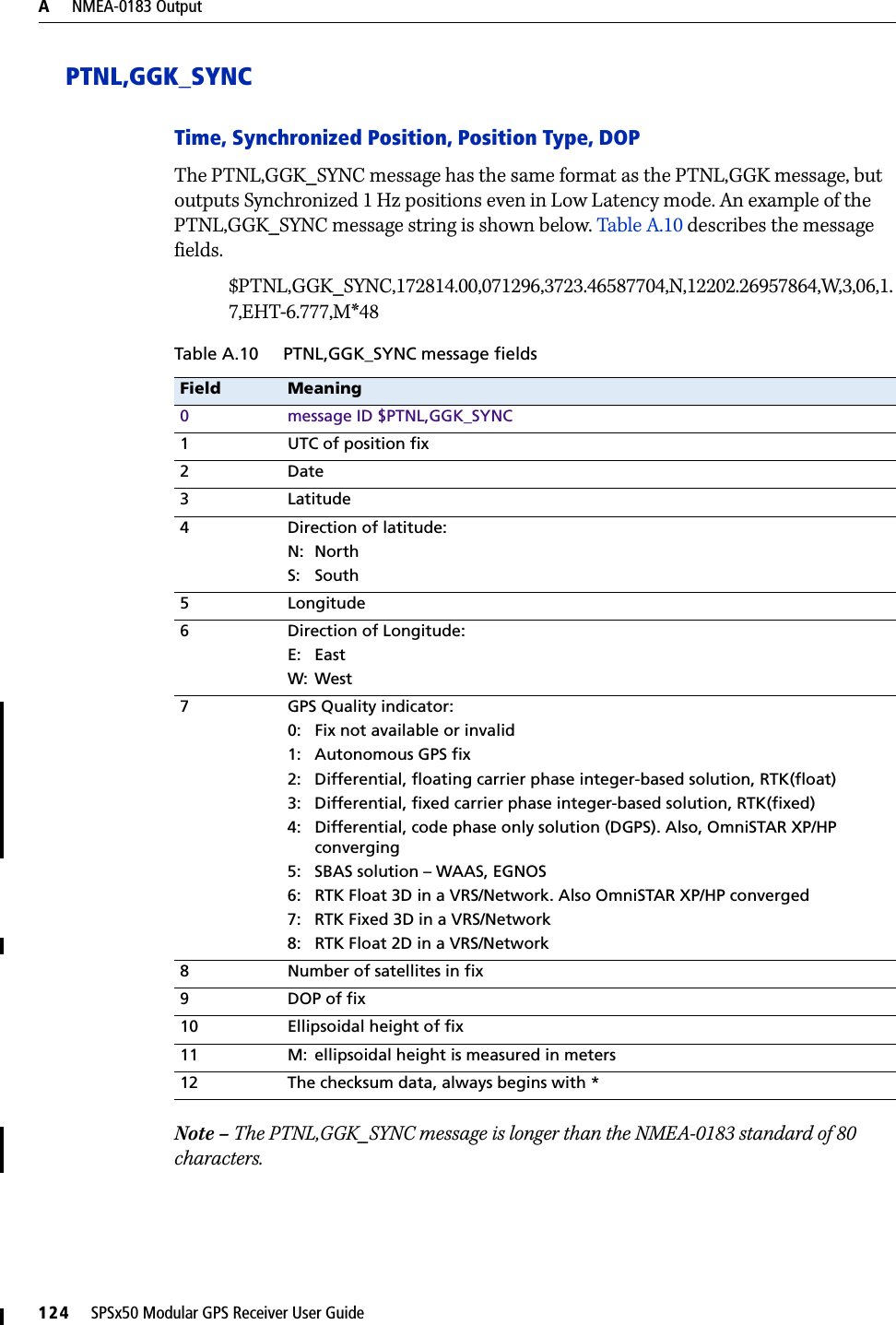
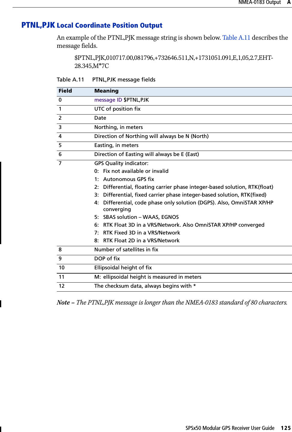
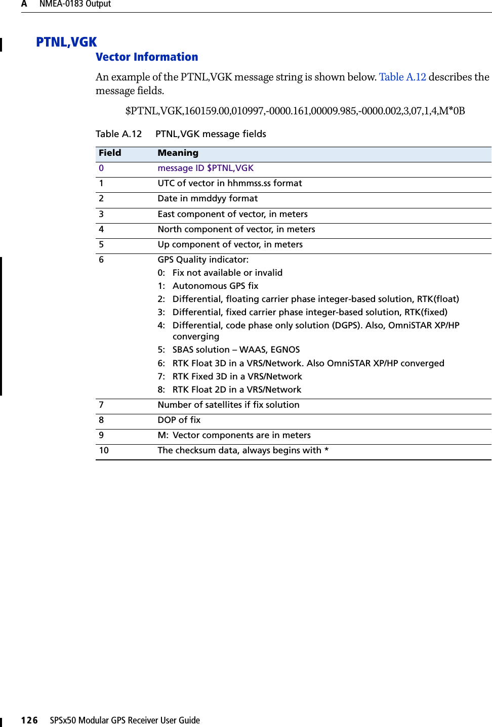
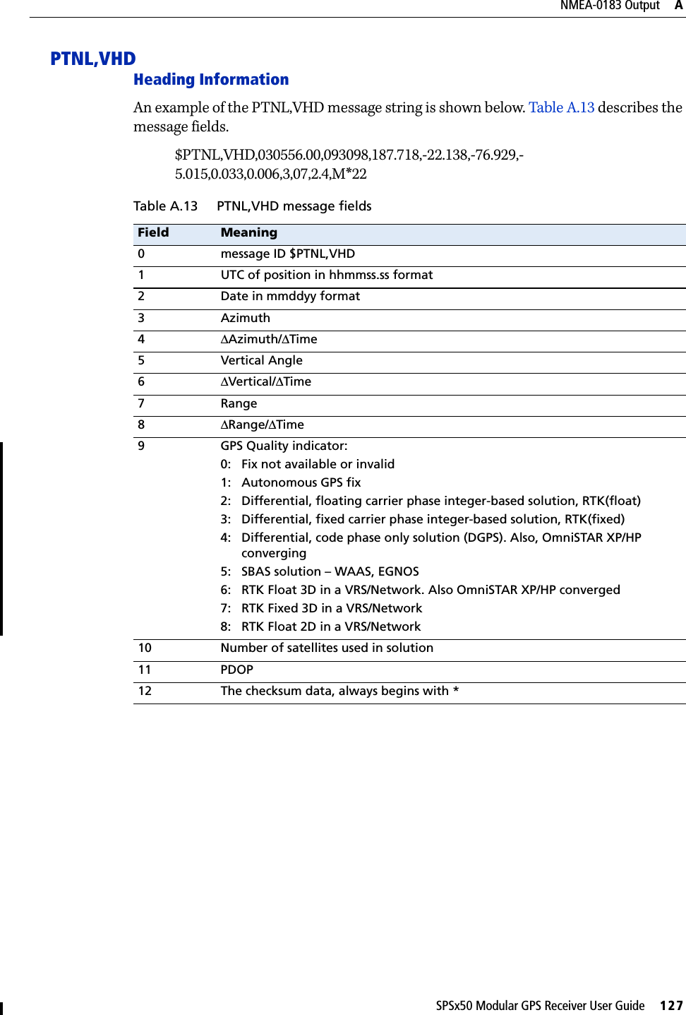
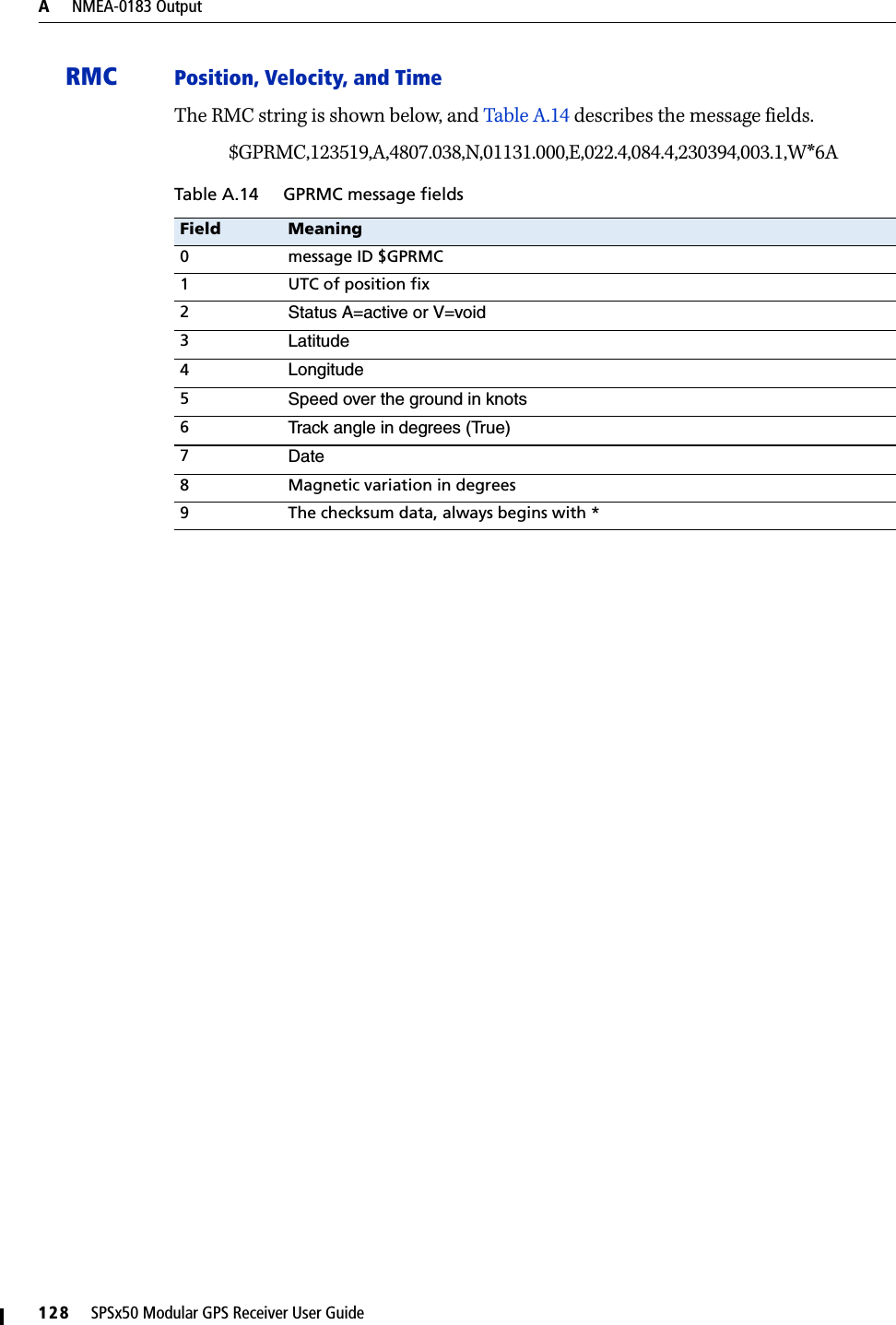
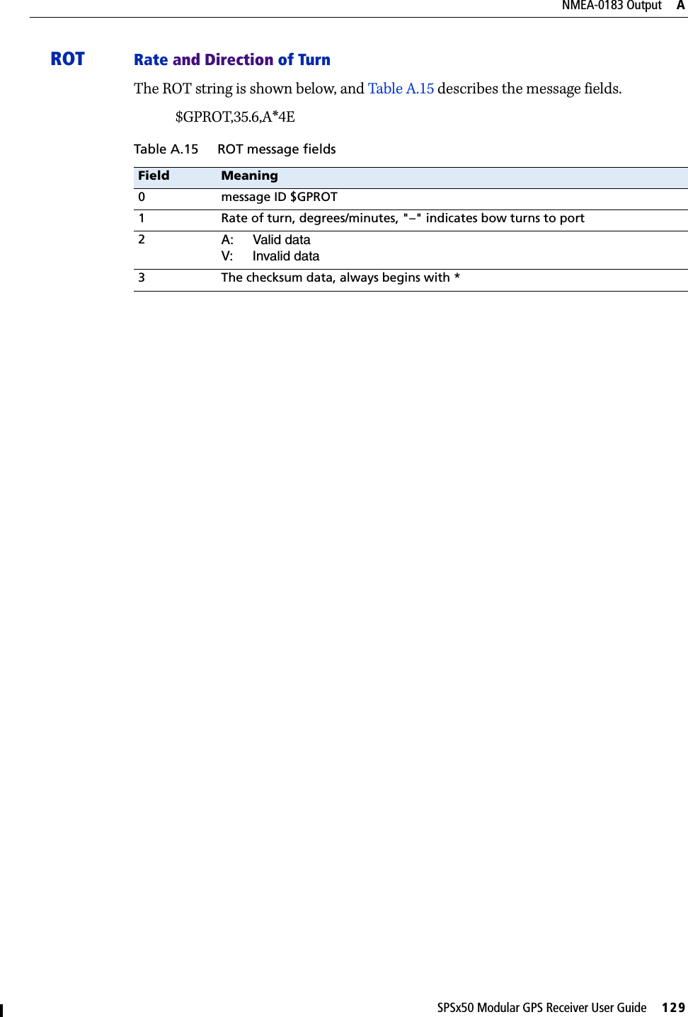
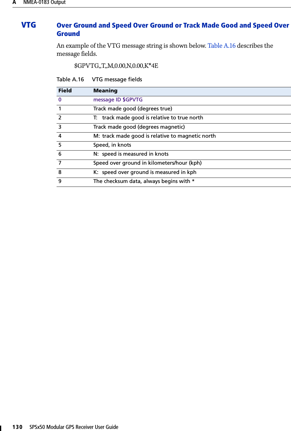
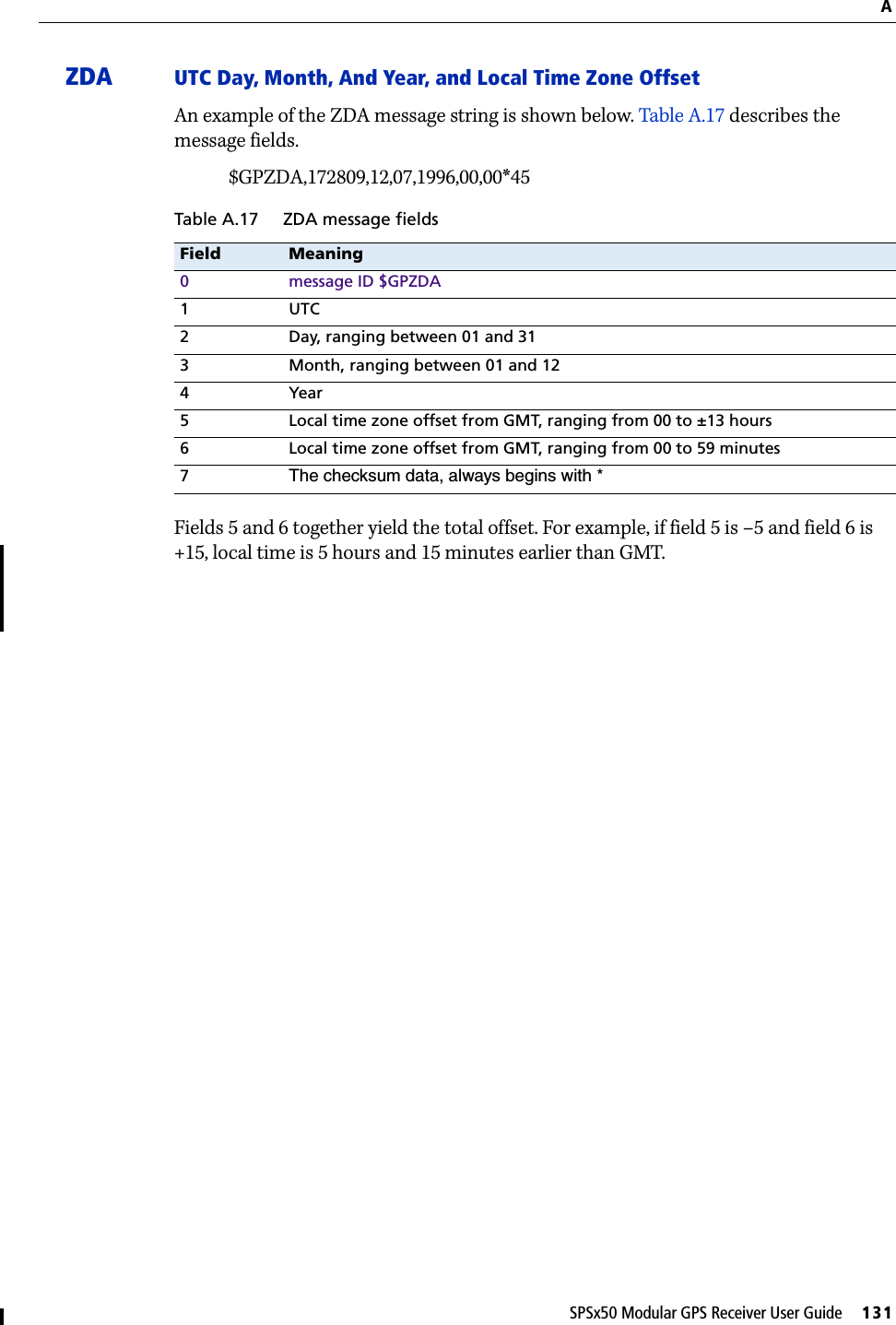
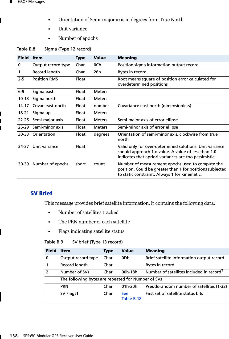
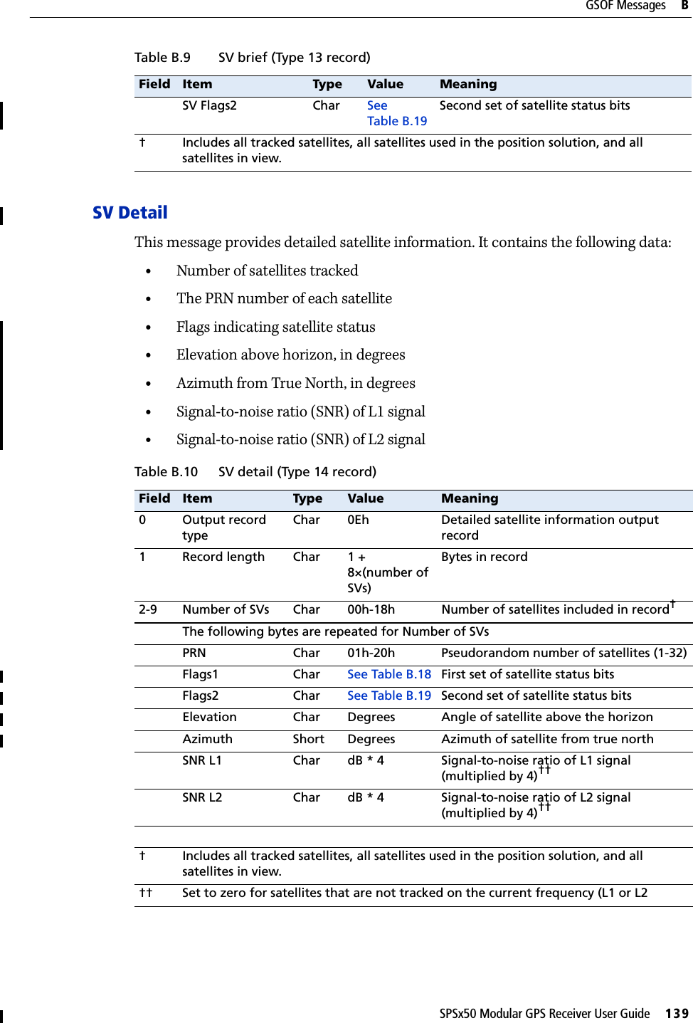
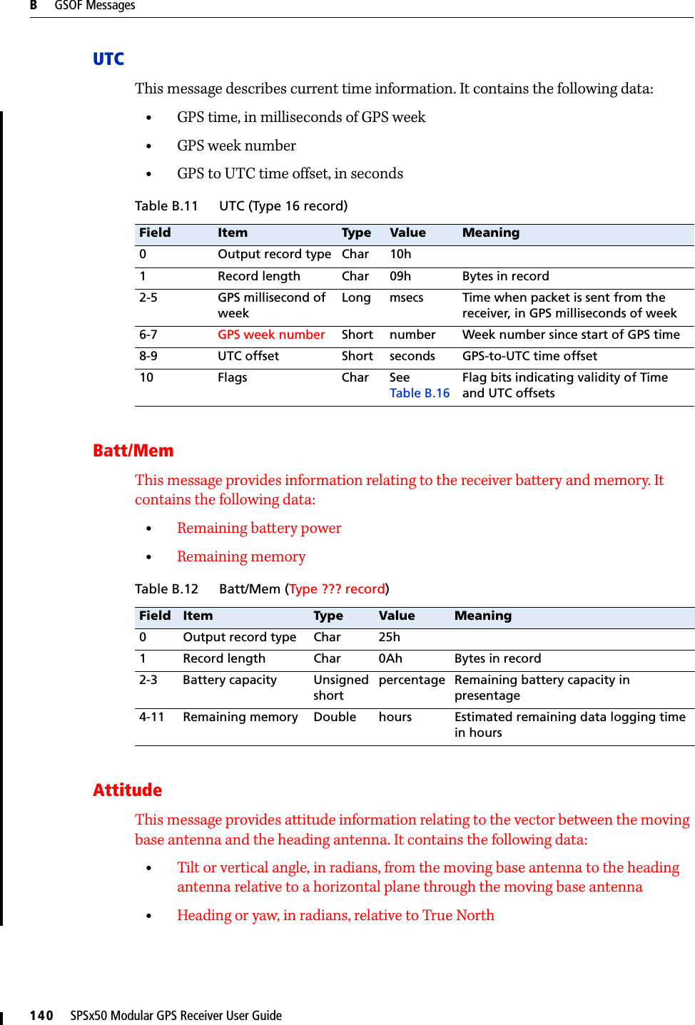
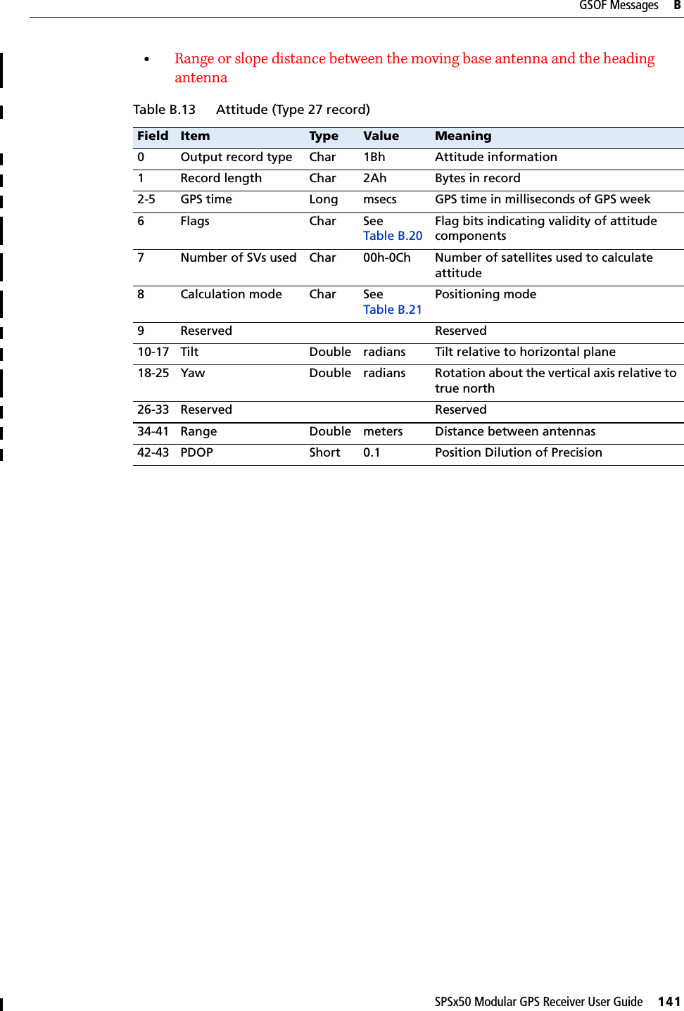
User Manual 2