Trapeze Software Group RAN48790 RUGGED AND COMPACT VEHICULAR COMPUTER User Manual INSTALL GUIDE
Trapeze Software Group, Inc. RUGGED AND COMPACT VEHICULAR COMPUTER INSTALL GUIDE
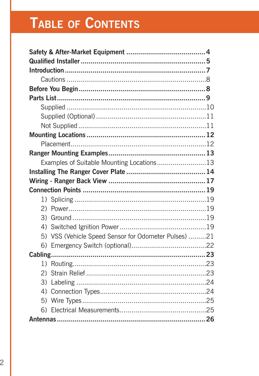
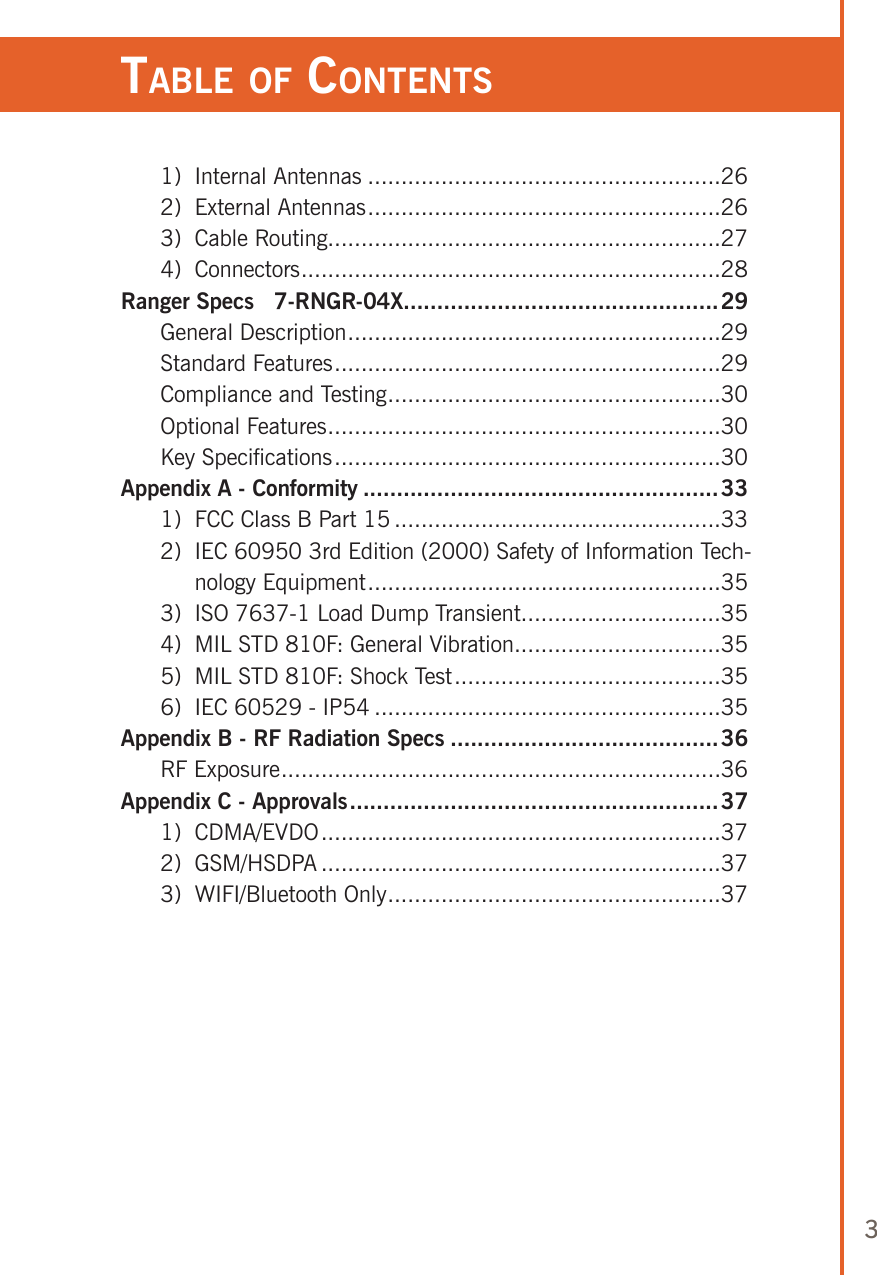
Contents
- 1. USERS INFO
- 2. RAGER INSTALL GUIDE
- 3. USER GUIDE
- 4. INSTALL GUIDE
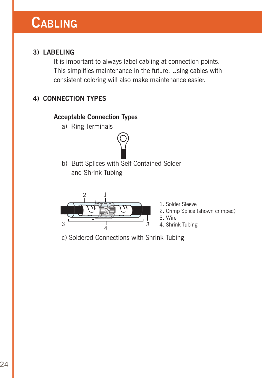
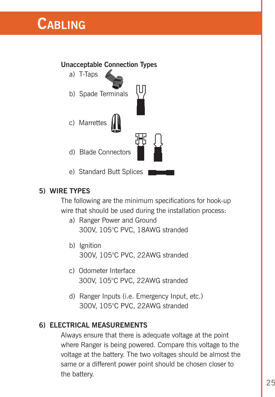
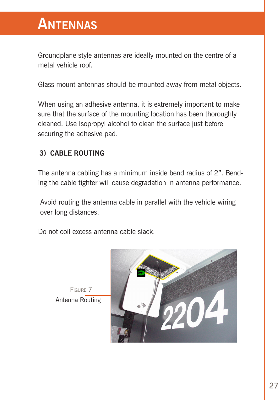
INSTALL GUIDE