Toshiba Client Solutions PL5080WL Libretto User Manual Manual 2of7
Toshiba Corporation Libretto Manual 2of7
UserManual.wiki
>
Toshiba Client Solutions
>
PL5080WL User Manual
>
Manual 2of7
Contents
1.
Manual 1of7
2.
Manual 2of7
3.
Manual 3of7
4.
Manual 4of7
5.
Manual 5of7
6.
Manual 6of7
7.
Manual 7of7
Manual 2of7
Navigation menu
Upload a User Manual
Namespaces
Wiki Guide
HTML
PDF
Info
Views
User Manual
Discussion / Help
Navigation
![100Hardware ResourcesYou can confirm the memory map, I/O port map and resources that use IRQ and DMA in thefollowing way.There are modifications depending upon the environment (hardware/software) that is being used.1. Click [Start], [All programs], [Accessories], [System tools] and [System information].2. Double click on [Hardware resource] in the tree on the left side of the screen.3. Click the items that you want to confirm.Memory map: [Memory]I/O port map: [I/O]Resources that use IRQ: [IRQ]Resources that use DMA: [DMA]](https://usermanual.wiki/Toshiba-Client-Solutions/PL5080WL.Manual-2of7/User-Guide-232987-Page-5.png)
![108Conformity StatementThe equipment has been approved to [Commission Decision “CTR21”] for pan-European singleterminal connection to the Public Switched Telephone Network (PSTN).However, due to differences between the individual PSTNs provided in differentcountries/regions the approval does not, of itself, give an unconditional assurance of successfuloperation on every PSTN network termination point.In the event of problems, you should contact your equipment supplier in the first instance.Network Compatibility StatementThis product is designed to work with, and is compatible with the following networks. It hasbeen tested to and found to confirm with the additional requirements conditional in EG 201 121.Germany - ATAAB AN005,AN006,AN007,AN009,AN010 andDE03,04,05,08,09,12,14,17Greece - ATAAB AN005,AN006 and GR01,02,03,04Portugal - ATAAB AN001,005,006,007,011 and P03,04,08,10Spain - ATAAB AN005,007,012, and ES01Switzerland - ATAAB AN002All other countries/regions - ATAAB AN003,004Specific switch settings or software setup are required for each network, please refer to therelevant sections of the user guide for more details.The hookflash (timed break register recall) function is subject to separate national typeapprovals. If has not been tested for conformity to national type regulations, and no guarantee ofsuccessful operation of that specific function on specific national networks can be given.](https://usermanual.wiki/Toshiba-Client-Solutions/PL5080WL.Manual-2of7/User-Guide-232987-Page-13.png)
![115TROUBLE CHECKLISTContact Toshiba PC Dial for information about operating your personal computer.TOSHIBA PC DIALTechnical questions can be answered on the telephone.* Hours: 9:00 to 19:00 (except for holidays and from December 31 to January 3)Navi-DialNational Common Telephone Number 0570-00-3100[Be careful to dial the correct telephone number to avoid making mistakes.]Customer inquiries are automatically connected to the nearest of six locations throughout thecountry (Chiba, Osaka, Nagoya, Fukuoka, Sendai and Sapporo).In Navi-Dial, an announcement about calling costs is made after dialing. This is the regular ratefor telephone calls to the location nearest to the customer; it is not a fee for technical support(there is no technical support fee).You should understand that Navi-Dial automatically uses NTT lines, even if you have contractedwith a different carrier or My-Line-Plus.The following calls will not connect with the above telephone system. Customers that fall intothis category should use 043-298-8780 (direct line).•Calls from overseas•Mobile phones and PHS•Connections made through telephone companies other than NTT such as 0088 or 0077.•General use contract lines for industry•Telephones that have been set to not use the “0570” by industry PBXTIPS:•Telephones that use the α-LCR/Super-LCR among others, can use “0570-00-3100”by disabling the settings, see the “manual attached to the telephone” for thedisabling procedure.•You can also receive product information, Q & A and other information by Fax (G3standard) from “Toshiba PC FAX Information Service”.•One on one consultation is available (technical consultation and labor are fee-based)at “Toshiba PC Techno-Center” (in Tokyo and Osaka).REFERENCE: For details see the “Guide to Toshiba PC Support”.](https://usermanual.wiki/Toshiba-Client-Solutions/PL5080WL.Manual-2of7/User-Guide-232987-Page-20.png)
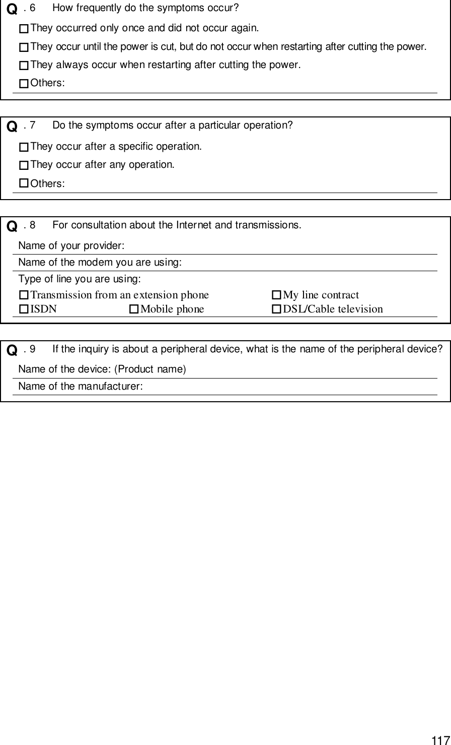
![116Trouble ChecklistFor smoother response, check the following details before contacting Toshiba.If Toshiba PC Dial asks you for information other than the following, such as the operatingsystem version and the type of CPU, check this information by clicking the [Basic InformationDisplay] button in [PC Diagnostic Tool].[Regarding the environment you are using(the personal computer environment that you are currently using).]Q . 1 What is the name (model name) of the personal computer that you are using?(See the computer itself or the operator’s manual)Name of device:Enquiry will be made about the following information.(Production number: , Placeof Purchase: , Date of Purchase: , etc.)Q . 2 What software environment are you using?Explain what system and application you are using, such as Windows XP Home.OS (System name):Others:Q . 3 What symptoms have occurred?Symptoms:Q . 4 After what operations did these symptoms occur?Details of operations:Q . 5 Did error messages or other things appear?Details of displays:](https://usermanual.wiki/Toshiba-Client-Solutions/PL5080WL.Manual-2of7/User-Guide-232987-Page-21.png)