Topcon RLSV Rotating Laser User Manual RL SV2S E 0628
Topcon Corporation Rotating Laser RL SV2S E 0628
UserManual.wiki
>
Topcon
>
RLSV User Manual
>
manual
Contents
1.
manual regularity part
2.
manual
manual
Navigation menu
Upload a User Manual
Namespaces
Wiki Guide
HTML
PDF
Info
Views
User Manual
Discussion / Help
Navigation
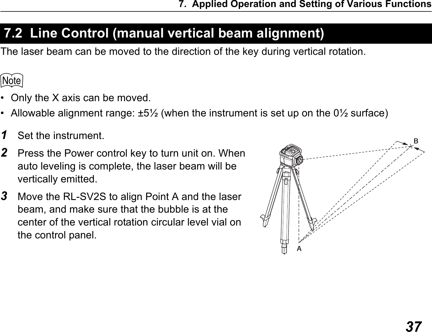
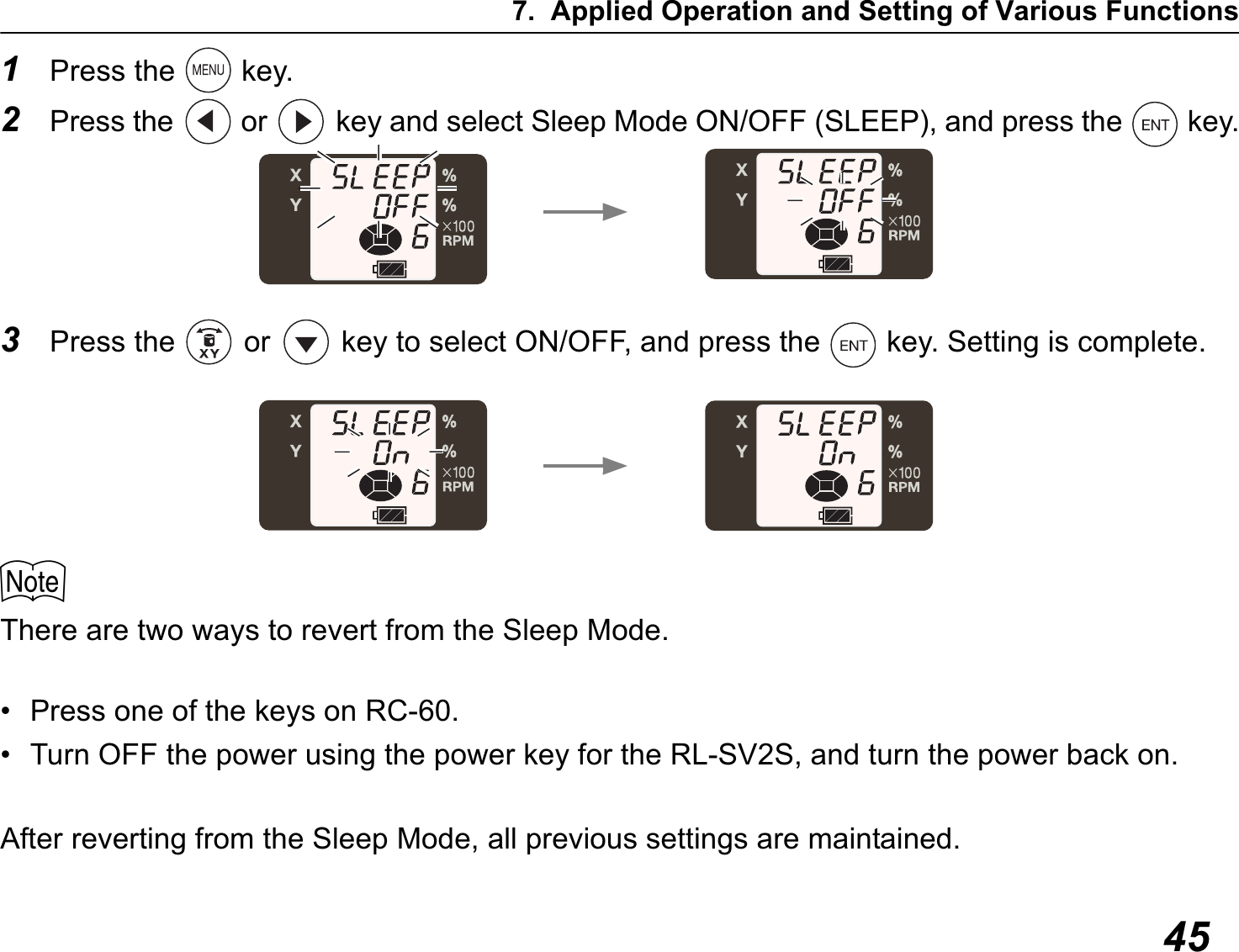
![6. Basic Operation263Press power switch on the LS-80L (ON).4Select the precision mode by pressing the On-Grade precision switch.C4.3 Level Sensor LS-80L(p. 15)5Locate the on-grade position “---” by moving the LS-80L up and down.6Mark the position of On-Grade index. (Top of the LS-80L is 40mm [1 9/16”] from index for offset marking.)](https://usermanual.wiki/Topcon/RLSV.manual/User-Guide-1491922-Page-34.png)
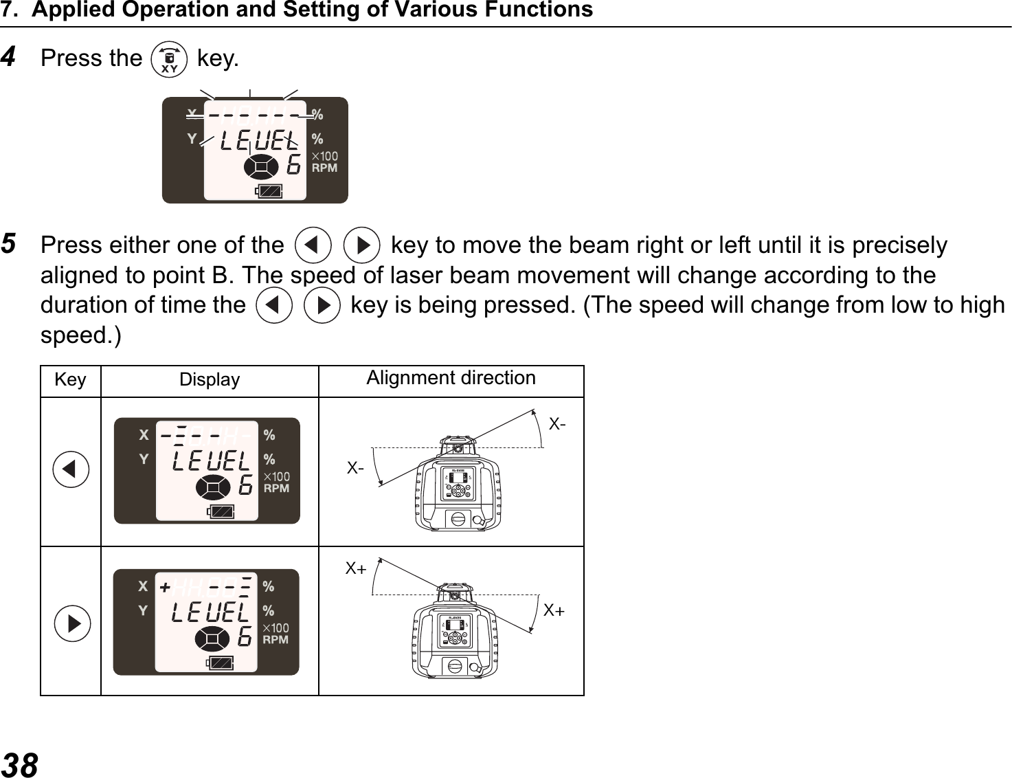
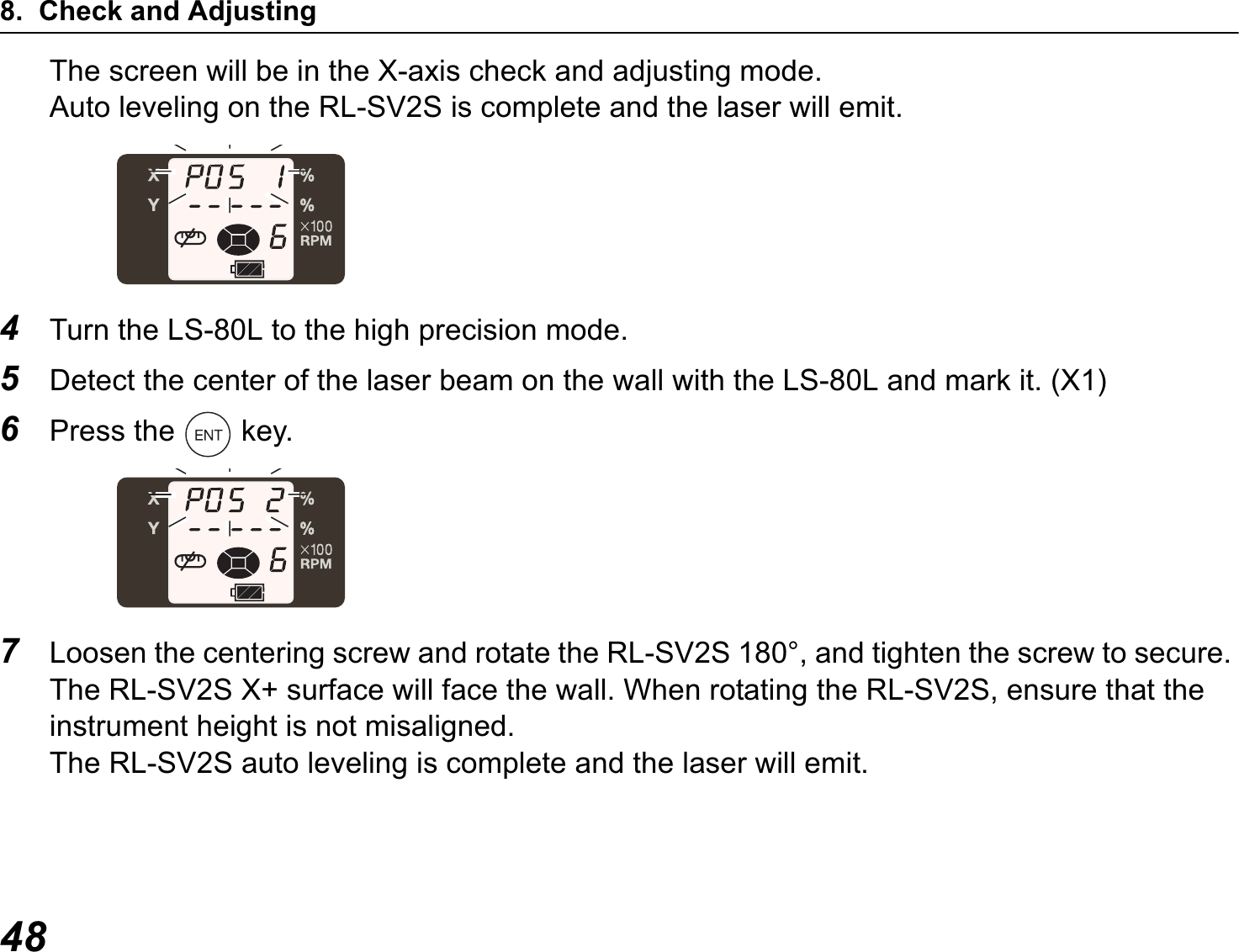
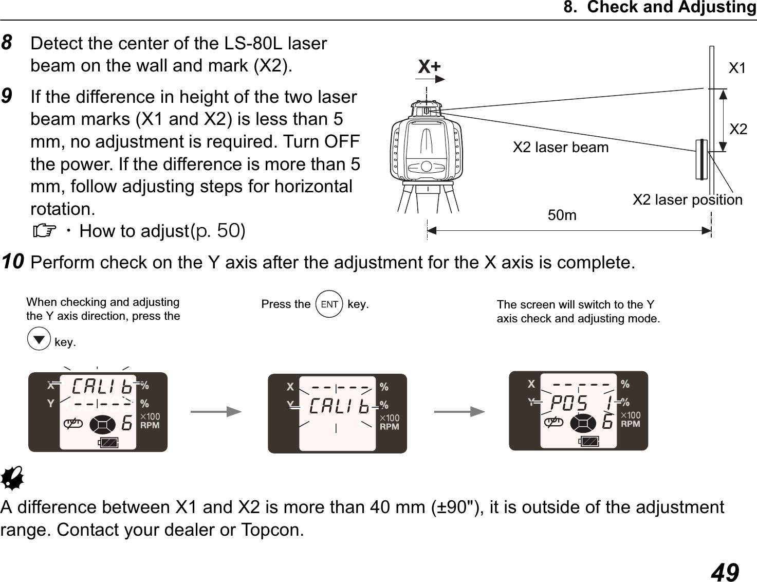
![478. CHECK AND ADJUSTINGPlease perform check and adjusting regularly. First check, and then make adjustments accordingly.Horizontal rotation grade error• How to check1Set up tripod approximately 50 meters away from a wall, and set the instrument on level with the X1 facing the wall.2While pressing the grade key, turn ON the power. (Only the main unit is operable). [CaLIb] will flash on the X axis screen. *1)3Press the key. (Hereafter, the RL-SV2S and RC-60 become operable.)8.1 Check and Adjust Horizontal Rotation50m (164feet)LS-80LStaff or WallY+Y-X-X+Control PannelHandleX- laser beamX- laser position](https://usermanual.wiki/Topcon/RLSV.manual/User-Guide-1491922-Page-55.png)
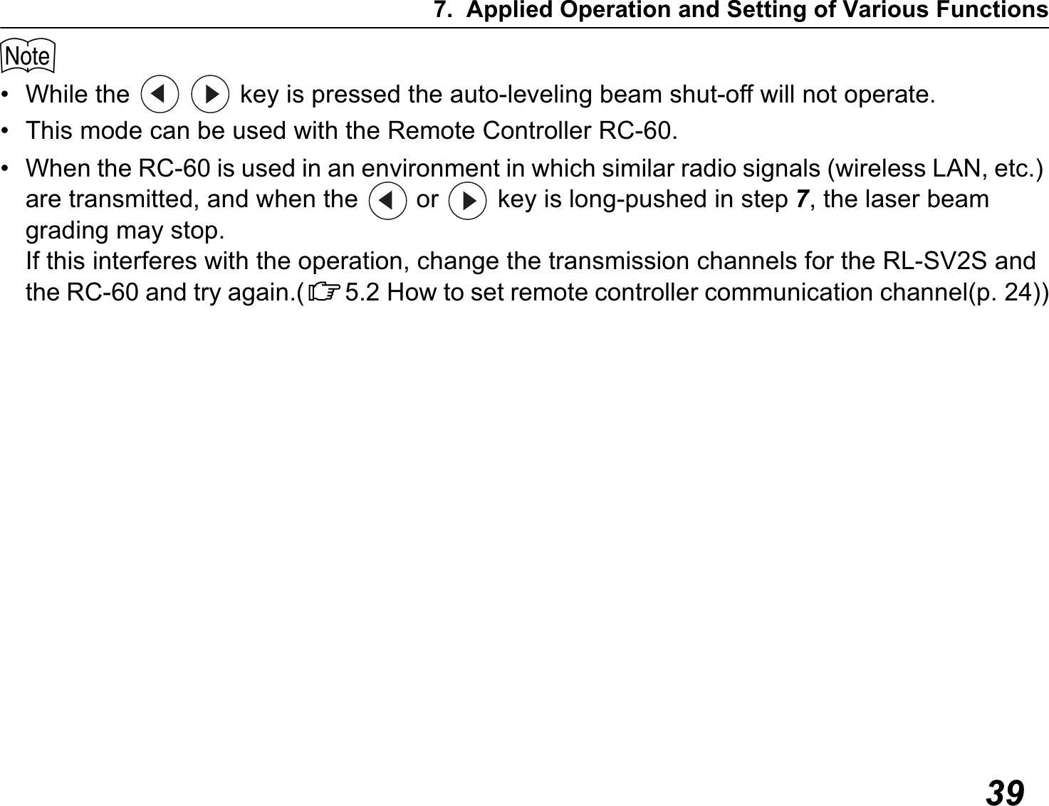
![8. Check and Adjusting50• How to adjust1According to step 9 of the horizontal rotation check, press the keys to move the laser beam between X1 and X2.2Press the key.ORAdjustment for X axis is complete.Exceeding the range of adjustment. C12. Error Display(p. 62)The RL-SV2S is calculating the correction value. Do not touch the RL-SV2S until [End] is displayed. (If you touch it, you will need to readjust.)](https://usermanual.wiki/Topcon/RLSV.manual/User-Guide-1491922-Page-58.png)
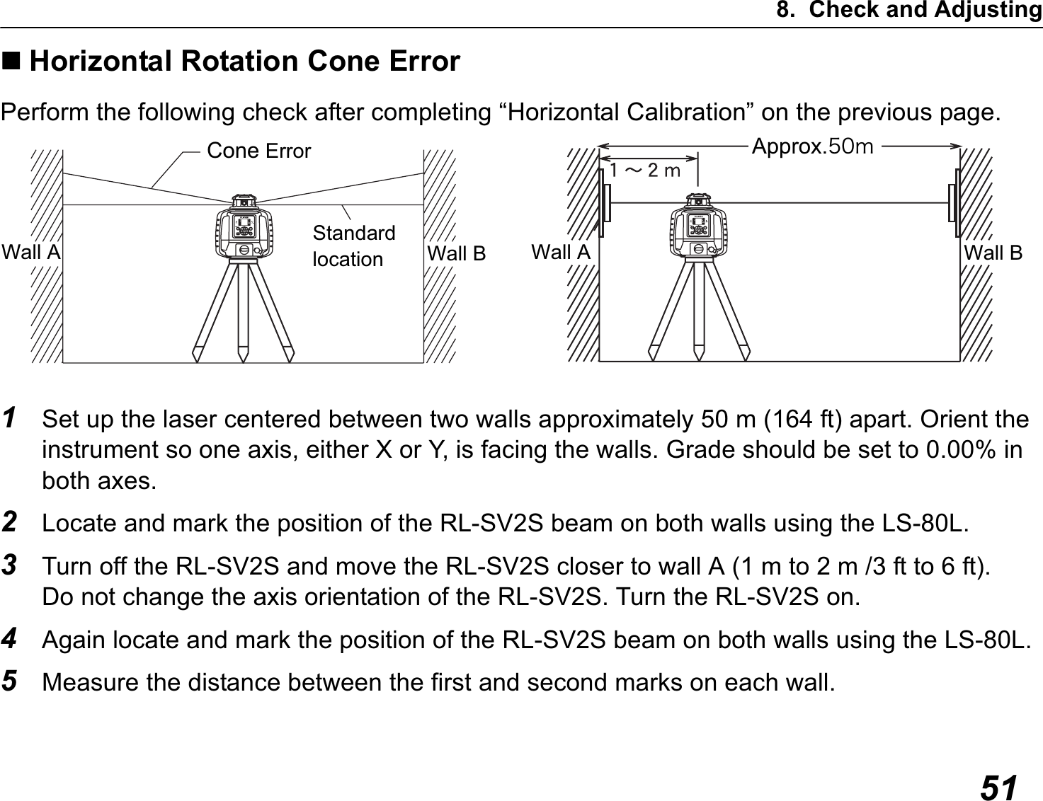
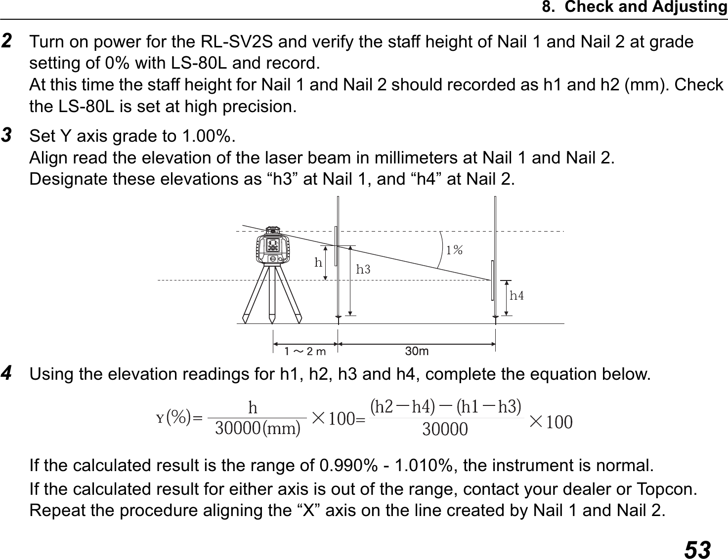
![8. Check and Adjusting526If the difference between each set of marks is less than ±5 mm (±7/32 of an inch), no error exists.GIf the difference between [wall A]-side and [wall B]-side exceeds ±5 mm (±7/32 of an inch), contact your dealer or Topcon.Grade Setting ErrorPerform the following check only after completing “Horizontal Calibration” and “Horizontal Rotation Cone Error”.• Checking1Setup the X- side facing the staff as shown in the figure.Securely position Nail 1 and Nail 2 exactly 30m apart.StaffÌÓ¸°ÌNail 1 Nail 2](https://usermanual.wiki/Topcon/RLSV.manual/User-Guide-1491922-Page-60.png)
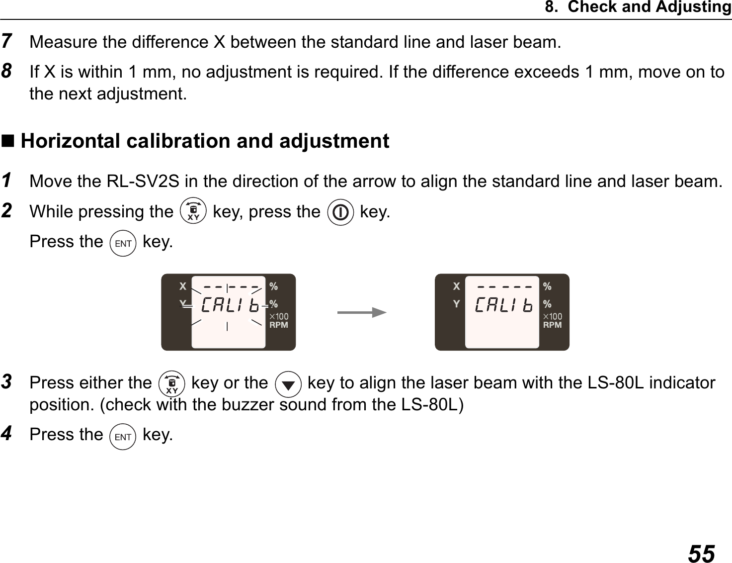
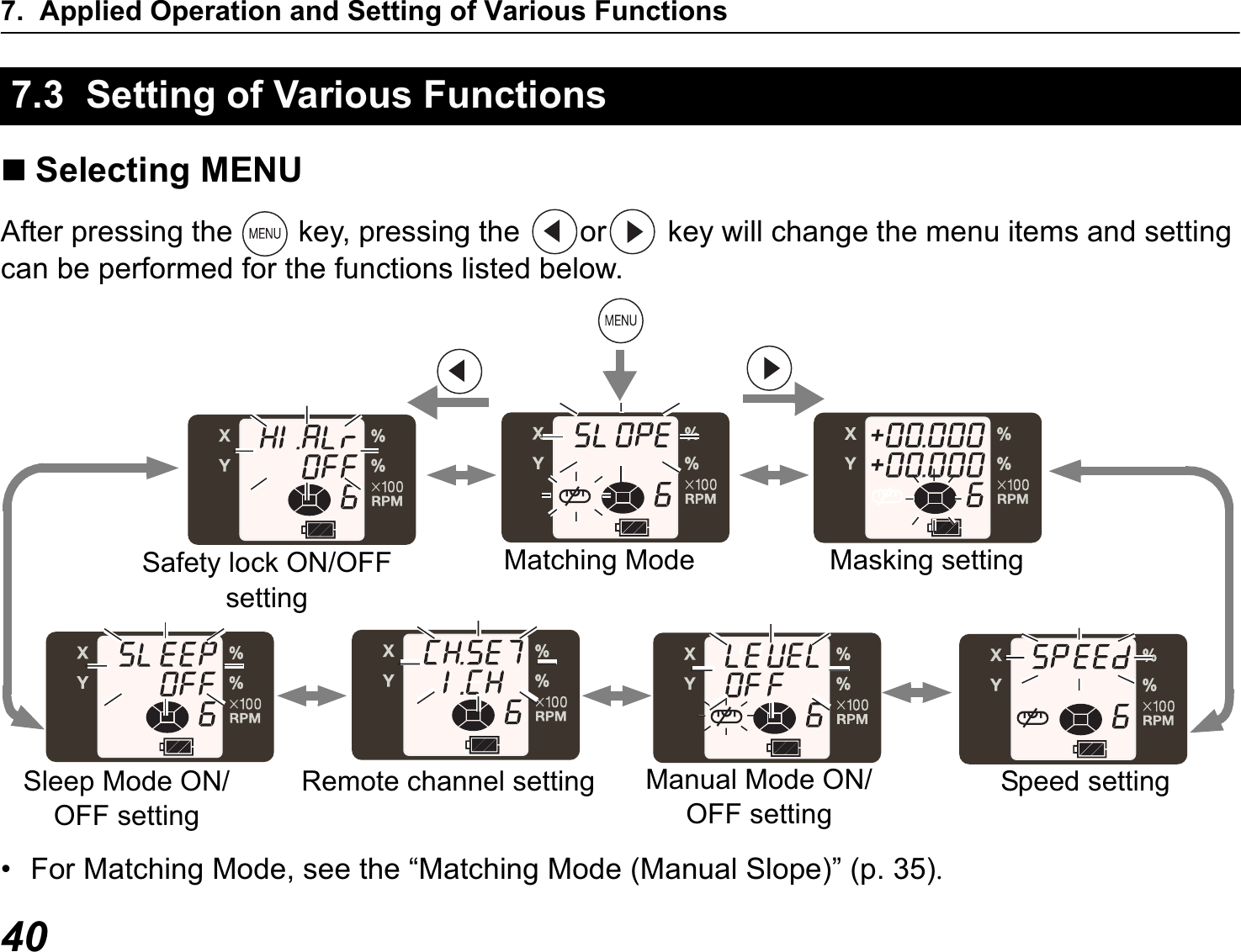
![8. Check and Adjusting56If the screen below is displayed, the adjustment is complete.$If [CALIb OVEr] is displayed C12. Error Display(p. 62)](https://usermanual.wiki/Topcon/RLSV.manual/User-Guide-1491922-Page-64.png)
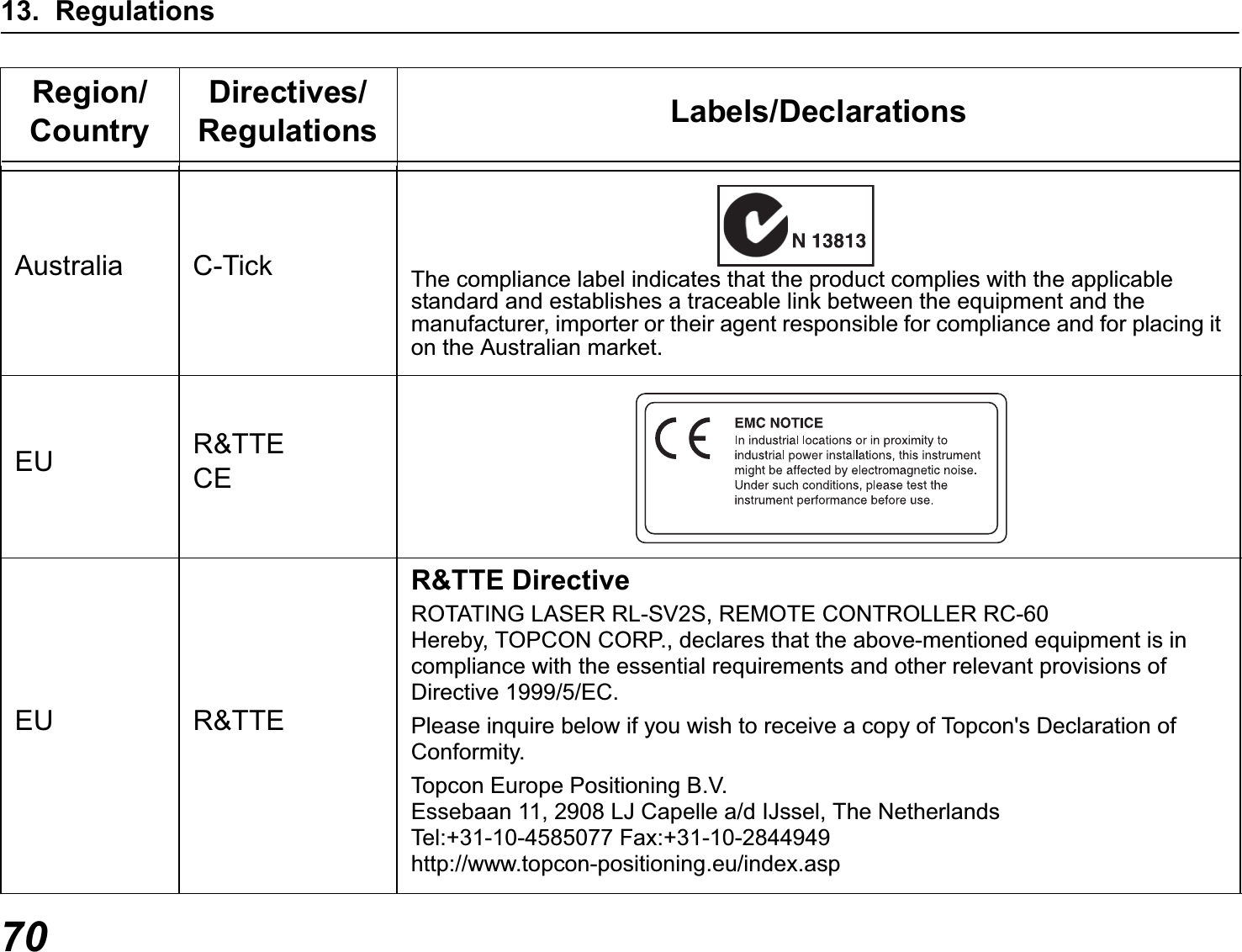
![11. Specifications60Protection against water and dust : IP66 (Based on the standard IEC60529)Operating temperature : –20 °C to +50 °C (–4 °F to +122 °F)Storable temperature range : –30 °C to +60 °C (–22 °F to +140 °F)ÌÓ÷áòîéîçäéóðìáù : RL-SV2S height alert warning(Warning is displayed on the indicator of LS-80L.)RL-SV2S battery warning(Warning is displayed on the indicator of LS-80L.)Dimensions : 177 (L) × 196 (W) × 217 (H) mm [7.0 (L) × 7.7 (W) × 8.5 (H) in]Laser beam height : 187mm(Height from the instrument’s bottom surface to the center point of laser beam)Weight : 2.5kg (lbs) (Dry battery type: Including dry batteries)2.7kg (lbs) (Ni-MH battery type: Including BT-74Q)Tripod screw : 5"/8X11 threads for surveying instrumentRC-60Operating range (Radius) : 100m or morePower source : 2×AA size dry cell batteriesContinuous operating time(+20°C): Approx. 3.5 months (depends on the nature of use)Protection against water and dust : IP66 (Based on the standard IEC60529)Operating temperature : –20 °C to +50 °C (–4 °F to +122 °F)Storable temperature range : –30 °C to +60 °C (–22 °F to +140 °F)Dimensions : 116 (L) × 59 (W) × 31.4 (H) mm [4.6 (L) × 2.3 (W) × 1.2 (H) in]Weight : 0.2kg (0.4lbs) (Including dry cell batteries)](https://usermanual.wiki/Topcon/RLSV.manual/User-Guide-1491922-Page-68.png)
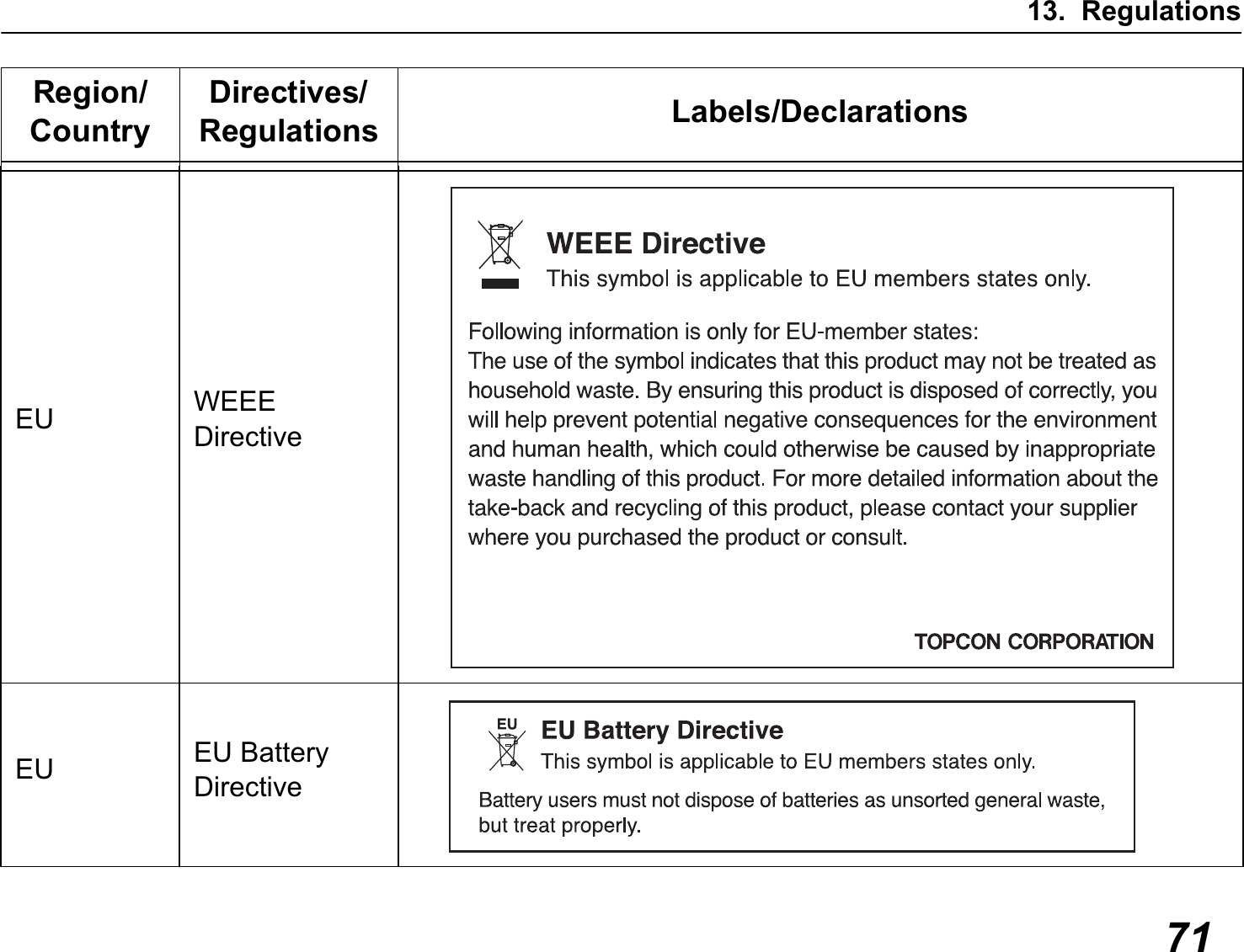
![11. Specifications61LS-80L (Back side display area)Beam detection window : 50 mm (2.0 in)Beam detection precision High precision : ±1 mm (±0.04 in) Normal precision : ±2 mm (±0.08 in)Beam detection indication : Liquid crystal (both sides) and buzzerPower source : 2×AA size dry cell batteriesOperating time : Approx. 120 hours (Using alkaline manganese dry cell batteries)Auto shut-off delay : Approx. 30 minutes without beamdetectionProtection against water and dust : IP66 (Based on the standard IEC60529)Operating temperature : -20°C to +50°C (-4°F to +122°F)Storage temperature : -30°C to +60°C (-22°F to +140°F)Dimensions : 146(L) x 76(W) x 26(H)mm (5.7 x 2.9 x 1.0 in)Weight : 0.19 kg [0.41 lbs] (including dry cell batteries)](https://usermanual.wiki/Topcon/RLSV.manual/User-Guide-1491922-Page-69.png)