Topcon RF-01 2.4GHz BAND DATA COMMUNICATION MODULE User Manual XE972

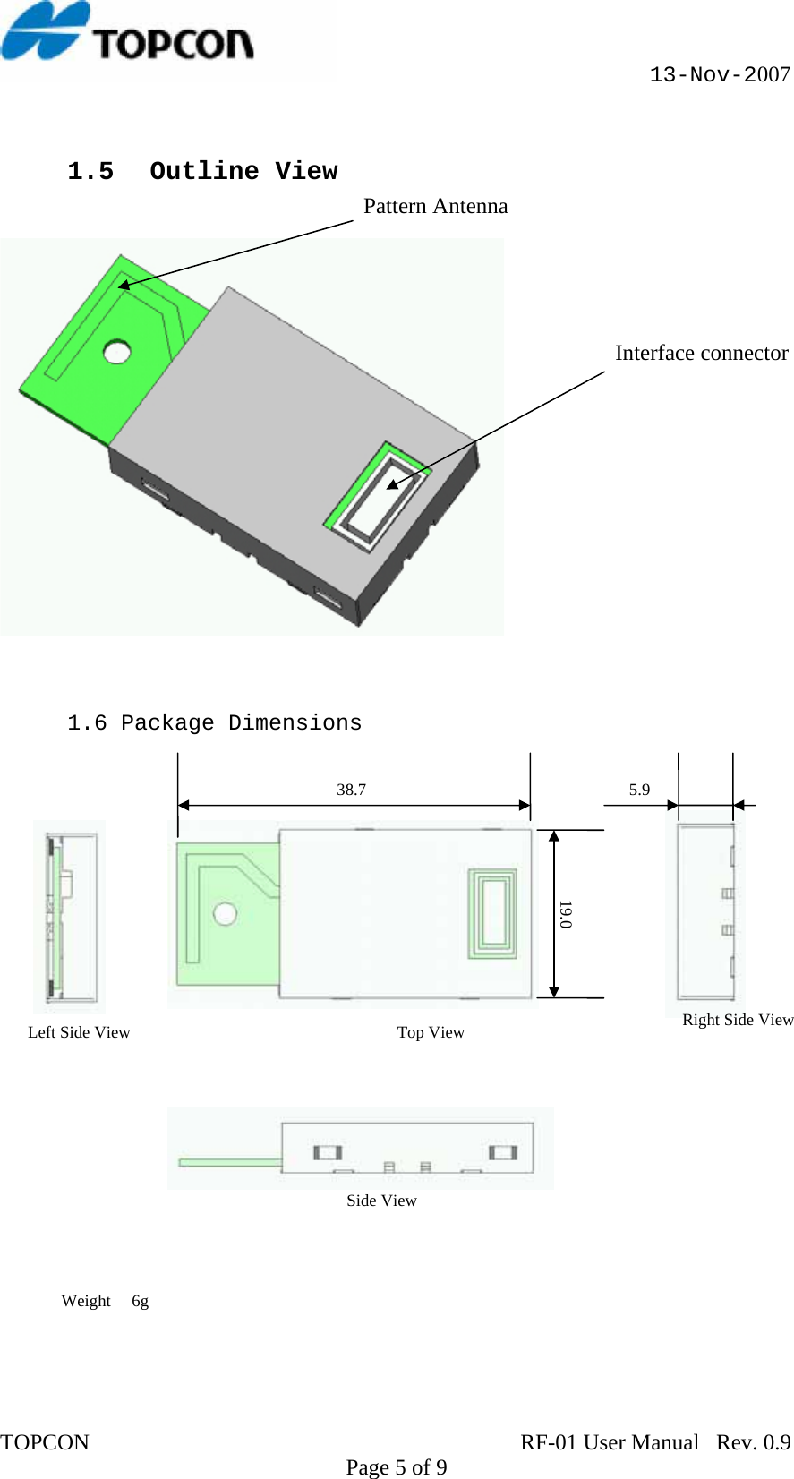
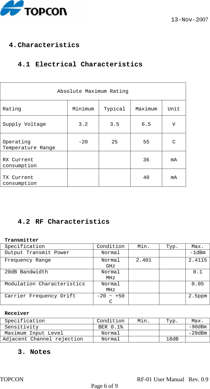
Topcon Corporation 2.4GHz BAND DATA COMMUNICATION MODULE XE972

Users Manual

                                                     13-Nov-2007     RF-01 User Manual     Confidential  TOPCON                                                                             RF-01 User Manual   Rev. 0.9    Page 1 of 9
                                                     13-Nov-2007  List of Contents       1.    General  1.1 Overview 1.2 Features 1.3 Application 1.4 Interface connecter pin assignment 1.5 Outline View  1.6 Package Dimensions  2. Characteristics 2.1 Electrical Characteristics 2.2 RF Characteristics   3. Notes TOPCON                                                                             RF-01 User Manual   Rev. 0.9    Page 2 of 9
                                                     13-Nov-2007  1. General  1.1 Overview  This specification covers RF-01 Data Radio Unit, which complies with  ARIB STD T-66, FCC Part 15 247 RSS-210 and  ETSI EN 300 400.  This unit consist of Texas CC2500 radio IC and Renesas CPU R8C19 for  Radio Data communication in 2.4GHz band.    All detailed specification may be changed  without notice.                         2.4GHz Antenna R8C19 RENESAS CPU CC2500 TEXAS RADIO IC  UART Interface TOPCON                                                                             RF-01 User Manual   Rev. 0.9    Page 3 of 9
                                                     13-Nov-2007  1.2 Features • Radio Data rate up to 32kbps. • Support Slow Hopping 22channels in 2.401GHz ~ 2.4115GHz • Ultra Low Power Consumption • RoHS Compliant • Support USART connection speed up to 115.2kbps • Small Package Size  (38.7  x 19.0 x 5.9)  • Integrated 26MHz Crystal Unit   1.3 Application • Radio Data Modem • Wireless Controller • Wireless Data Logger • Wireless Security Sensor  1.4 Interface connecter pin assignment  TOP Side View of RF-01                      20 19 211.2. VB  (Power In)            3.4. GND (Power GND)  5.6. CS (Carrier Sense)        7.8. PWR CONT (Unit Power Control)  9.10. PTT (Transmit Switch)    11.12. GD MONI(Not Used)  13.14. RXD(UART RXD)           15.16. TXD(UART TXD)  17. RTS(UART RTS)              18. MODE(Not Used)  19. CTS(Not Used)              20. RESET (Unit Reset)   TOPCON                                                                             RF-01 User Manual   Rev. 0.9    Page 4 of 9
                                                     13-Nov-2007  1.5  Outline View    Pattern Antenna  Interface connector    1.6 Package Dimensions   Left Side View  Top View Side View Weight     6g  38.7 19.0 5.9 Right Side ViewTOPCON                                                                             RF-01 User Manual   Rev. 0.9    Page 5 of 9
                                                     13-Nov-2007  4. Characteristics   4.1 Electrical Characteristics    Absolute Maximum Rating   Rating  Minimum  Typical  Maximum  Unit  Supply Voltage    3.2   3.5   6.5   V   Operating Temperature Range  -20  25  55  C   RX Current consumption    36  mA    TX Current cons     40  mA umption   4.2 RF Characteristics    Transmitter pecification Condition Min. Typ. Max. SOutput Transmit P     -1dBmower  Normal Frequency Range GHz2.401  2.4115Normal   20dB Bandwidth  N 0.1 ormal MHz   Modulation Characteristi NorM0.05 cs  mal Hz   Carrier Frequency Drift  -20 ~ +50 C   2.5ppm Receiver Specification Condition Min. Typ. Max. Sensitivity B  0.1%  -90dBmER   Maximum Input Level  rmal      -20dBmNoAdjacent Channel rejec on  rmal  18dB   ti No   3. Notes TOPCON                                                                             RF-01 User Manual   Rev. 0.9    Page 6 of 9
                                                     13-Nov-2007  FCC Statements:    Operation is subject to the following two conditions: evice may not cause harmful interference, and ice must acce ter ce  vence tha ause  desire    C S NO Y AP ROVED B  THMANUFACTURER FOR COMPLIANCE COULD VOID THE USER’S AUTHORITY TO OPERATE THE EQUIPMENT   C  device and it a(s t n  r operat onjun ion wi  anor t ter.  d us nnot this transmitter device. Any unauthorized cation made on the device could avoid the thority to operate this device. requirements, a separation distance of at least   The following sentence has to be displayed on the outside of the device in which the transmitter module is installed: “Cis equipment has been tested and found to comply with the mits for a Class B digital device, pursuant to part 15 of e FCC Rules. These limits are designed to provide rdance with the instructions, may use harmful interference to radio communications.   This device complies with Part 15 of the FCC Rules. (1) this d(2) this dev pt any in feren recei d, including interfere t may c un d operation. HANGES OR MODIFICATION T EXPRESSL P Y E AUTION:  This s antenni)  usm ot be  co-located o ng in c ct th y other antenna  ransmit En er ca  modifymodifiuser's au CAUTION:  To comply with FCC RF exposure compliance 20cm must be maintained between the antenna of this device and all persons. ontains FCC ID:H5PRF-01  Thlithreasonable protection against harmful interference in a residential installation. This equipment generates, uses and can radiate radio frequency energy and, if not nstalled and used in accoica However, there is no guarantee that interference will notTOPCON                                                                             RF-01 User Manual   Rev. 0.9    Page 7 of 9
                                                     13-Nov-2007 occur in a particular installation. If this equipment does cause harmful interference to radio or television reception, which can be determined by turning the equipment off and on, the user is encouraged to try to correct the interference by one or more of the following measures:  - Increasreceiver.  - Connect the equipment into an outlet on a circuit fferent from that to which the receiver is connected.  Consult the dealer or an experienced radio/TV technician  - Reorient or relocate the receiving antenna. e the separation between the equipment and di -for help.    TOPCON                                                                             RF-01 User Manual   Rev. 0.9    Page 8 of 9
                                                     13-Nov-2007 IC  Statements:    The term “IC:” before the radio certification number only signifies that Industry Canada technical specifications were met. This device complies with RSS 210 of Industry Canada “IC”. “Operation is subject to the following two conditions: (1) this device may not cause interference, and  (2) this device must accept any interference, including interference that may cause undesired operation of the device.”  "The installer of this radio equipment must ensure that the antenna is located or pointed such that it does not emit RF field in excess of Health Canada limits for the general population; consult Safety Code 6, obtainable from Health Canada’s website www.hc-sc.gc.ca/rpb"  L’ utililisation de ce dispositif est autorisée seulement aux conditions suivantes :  (1) il ne doit pas produire de brouillage et  (2) l’ utilisateur du dispositif doit étre prêt  à accepter tout brouillage radioélectrique  reçu, même si ce brouillage est susceptible de compromettre le fonctionnement du dispositif.   "The installer of this radio equipment must ensure that the antenna is located or pointed such that it does not emit RF field in excess of Health Canada limits for the general population; consult Safety Code 6, obtainable from Health Canada’s website www.hc-sc.gc.ca/rpb"   “To reduce potential radio interference to other users, the antenna type and its gain should be so chosen that the equivalent isotropically radiated power (e.i.r.p.) is not more than that permitted for successful communication.”     The following sentence has to be displayed on the outside of the device in which the transmitter module is installed: “Contains IC:6050A-RF01 TOPCON                                                                             RF-01 User Manual   Rev. 0.9    Page 9 of 9

Navigation menu