Topcon RD-100W Remote Display User Manual RD 100W E
Topcon Corporation Remote Display RD 100W E
UserManual.wiki
>
Topcon
>
RD 100W User Manual
user manual
Navigation menu
Upload a User Manual
Namespaces
Wiki Guide
HTML
PDF
Info
Views
User Manual
Discussion / Help
Navigation
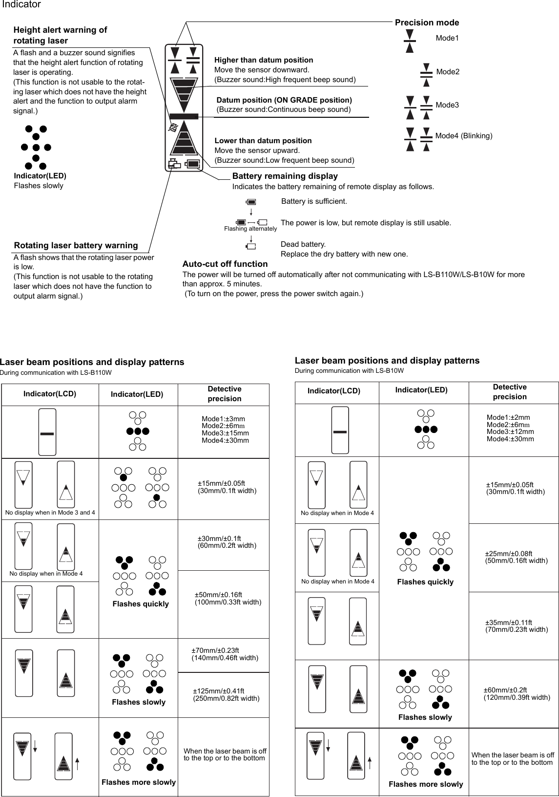
![Nomenclature and FunctionsMagnetIndicator(LCD)Power switchPower ON: Short pushPower OFF: Long pushLCD back light ON/OFF: Short push when power is ON(Auto turn-off after two minutes)Detective precision (Mode) switchBuzzer sound switchBuzzer sound: Quiet/Loud/OFF:Short push LED ON/OFF: Long pushIndicator(LED)Buzzer speakerRisk of damage to installation surface of machine, because it uses a strong magnet.See [Laser beam positions and display patterns] in the Instruction manual for the display area and display pattern.This instrument is able to perform wireless communication with the LS-B110W/LS-B10W, sold separately.See the LS-B110W/LS-B10W Instruction manual for details on the LS-B110W/LS-B10W.Wireless communication switchCommunication ON/OFF: Short pushCommunication default setting: Long pushWireless communication LEDTilt switchZero-set switchBattery coverBattery cover knobHow to set up the wireless communication default settingPlace the LS-B110W/LS-B10W and RD-100W in close position, so that they will not be affected by other wireless communications.1Turn on the power for both the LS-B110W/LS-B10W and RD-100W.2Long-push the wireless communication switch for the LS-B110W/LS-B10W and RD-100W. While setting up, the wireless communi-cation LED (yellow light) will turn on.3When the instrument is ready to be used, a buzzer will sound (buzzer sound: peep) and the communication will begin. How to use wireless communication1When power for both the LS-B110W/LS-B10W and RD-100W are turned ON, communication will automatically begin.During communication, the wireless communication LED will flash quickly.During communication preparation, the wireless communication LED will flash slowlyLighting/Flashing pattern of wireless communication LEDLights While setting up the defaultFlashes quickly While LS-B110W/LS-B10W is communicatingFlashes slowly Communication is in preparation• If the communication fails, a buzzer will sound (buzzer sound: pi, pi, pi). Eliminate any influence from other wireless instrument and redo the communication default setting.• While setting up the default, only the default OFF (short-push of the wireless communication switch) is operable.• When beginning the communication with LS-B110W, detective precision, tilt direction, tilt precision and ON-GRADE position setting will be changed to the same setting as the LS-B110W.• When the detective precision, tilt direction, tilt precision or ON-GRADE position settings are changed while communicating with LS-B110W, the setting for the LS-B110W will also change in conjunction with the RD-100W.• When begining the communication with LS-B10W, detective precision, buzzer sound, LED ON/OFF setting will be changed to the same setting as the LS-B10W.• When the detective precision, buzzer sound or LED ON/OFF settings are changed while communicating with LS-B10W, the setting for the LS-B10W will also change in conjunction with the RD-100W.• If you wish to change the LS-B110W/LS-B10W to communicate, redo the communication default setting.](https://usermanual.wiki/Topcon/RD-100W/User-Guide-920255-Page-2.png)