Thermo MeasureTech 1440-15 Model 1440 Radar Level Gauge User Manual AccuWave Installation Manual
Thermo MeasureTech Model 1440 Radar Level Gauge AccuWave Installation Manual
Contents
- 1. Operating Manual for 1440
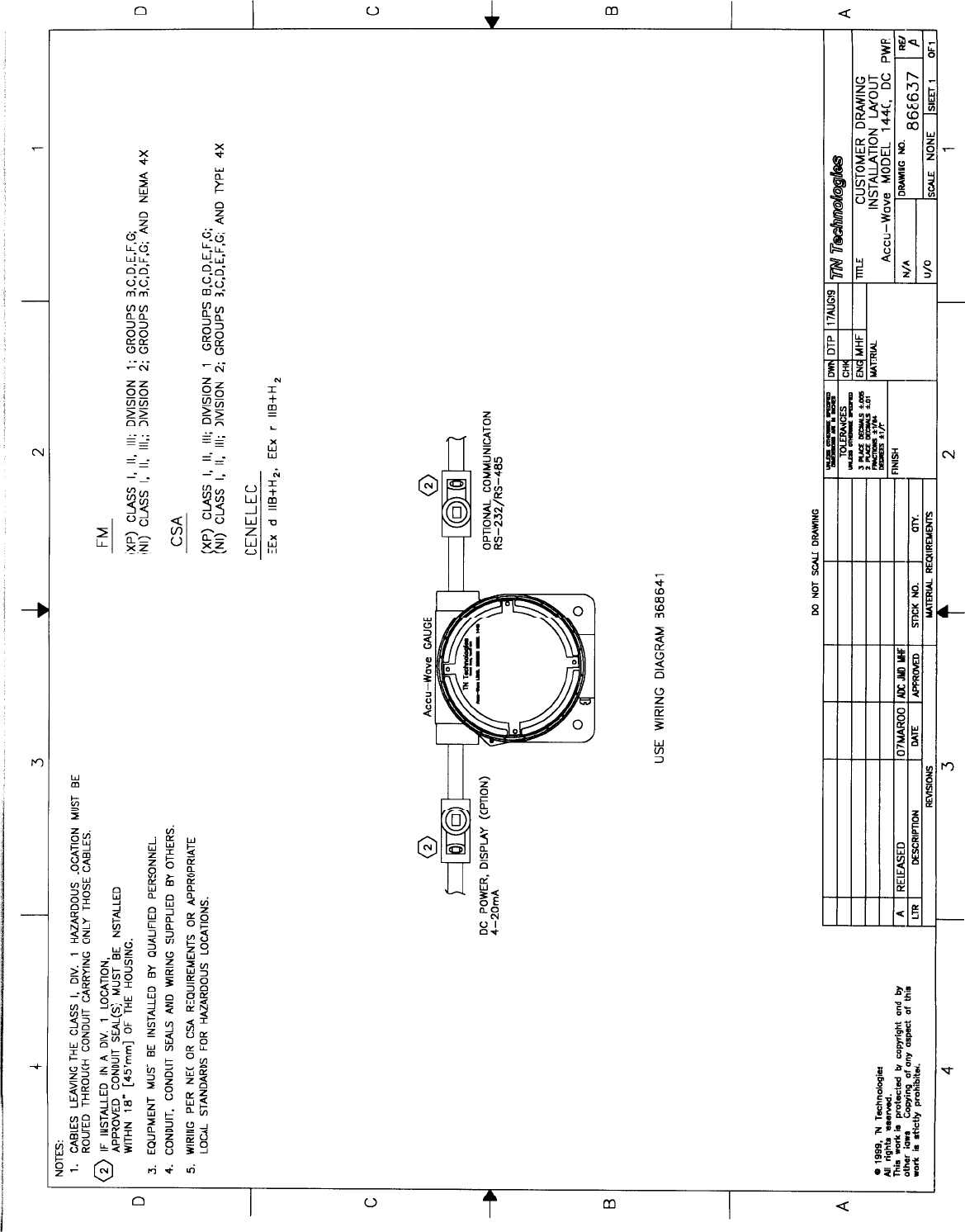
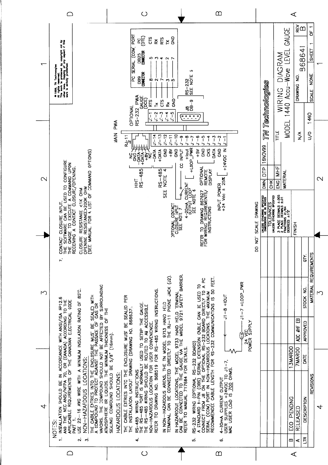
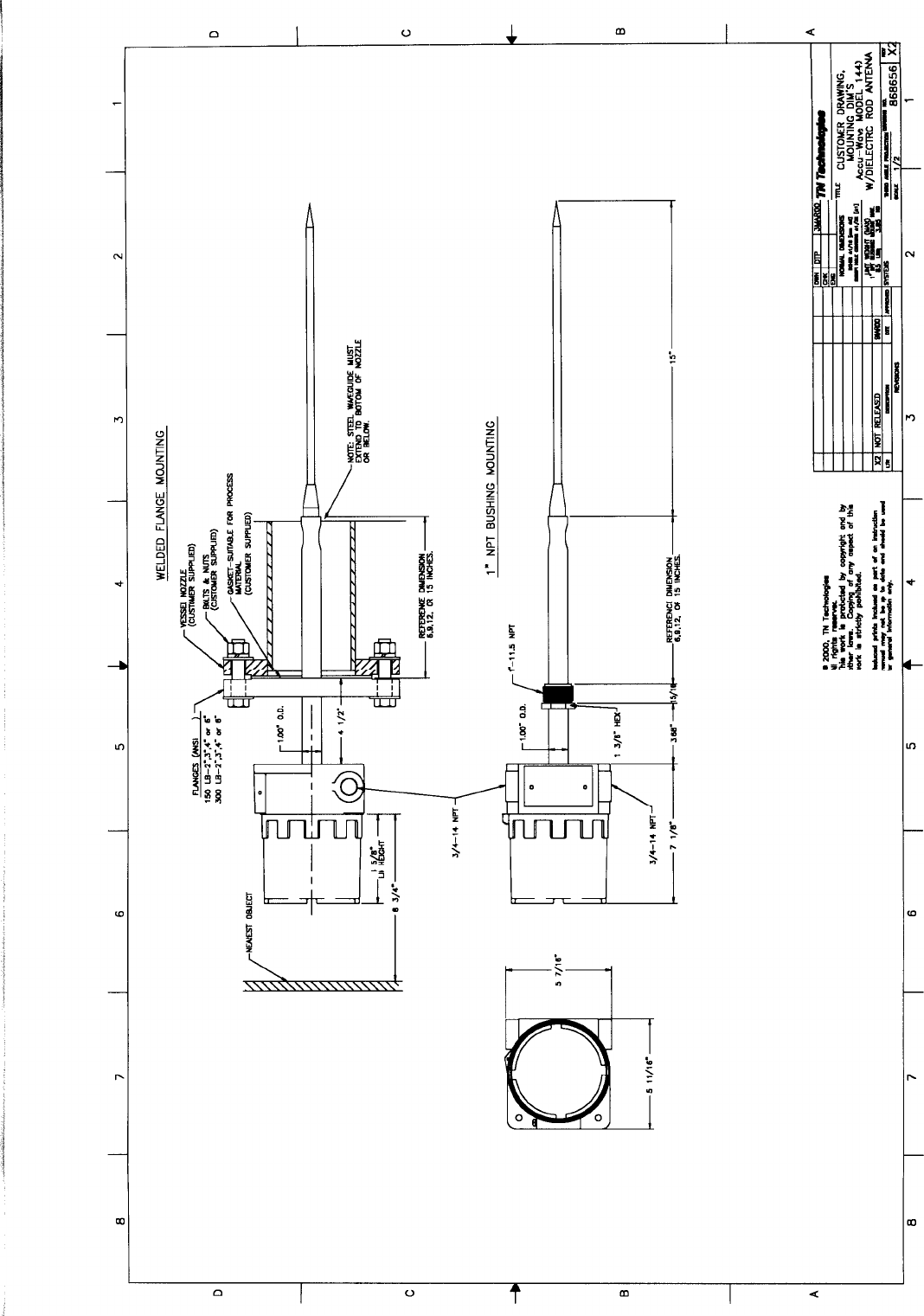
- 2. Installation Manual for 1440
Installation Manual for 1440