The Watt Stopper d b a Qmotion EX11059 Qmotion Qconnect User Manual 11 0364 Exhibit Cover
HomeRun Holdings Corp. Qmotion Qconnect 11 0364 Exhibit Cover
UserManual.wiki
>
The Watt Stopper d b a Qmotion
>
EX11059 User Manual
Manual
Navigation menu
Upload a User Manual
Namespaces
Wiki Guide
HTML
PDF
Info
Views
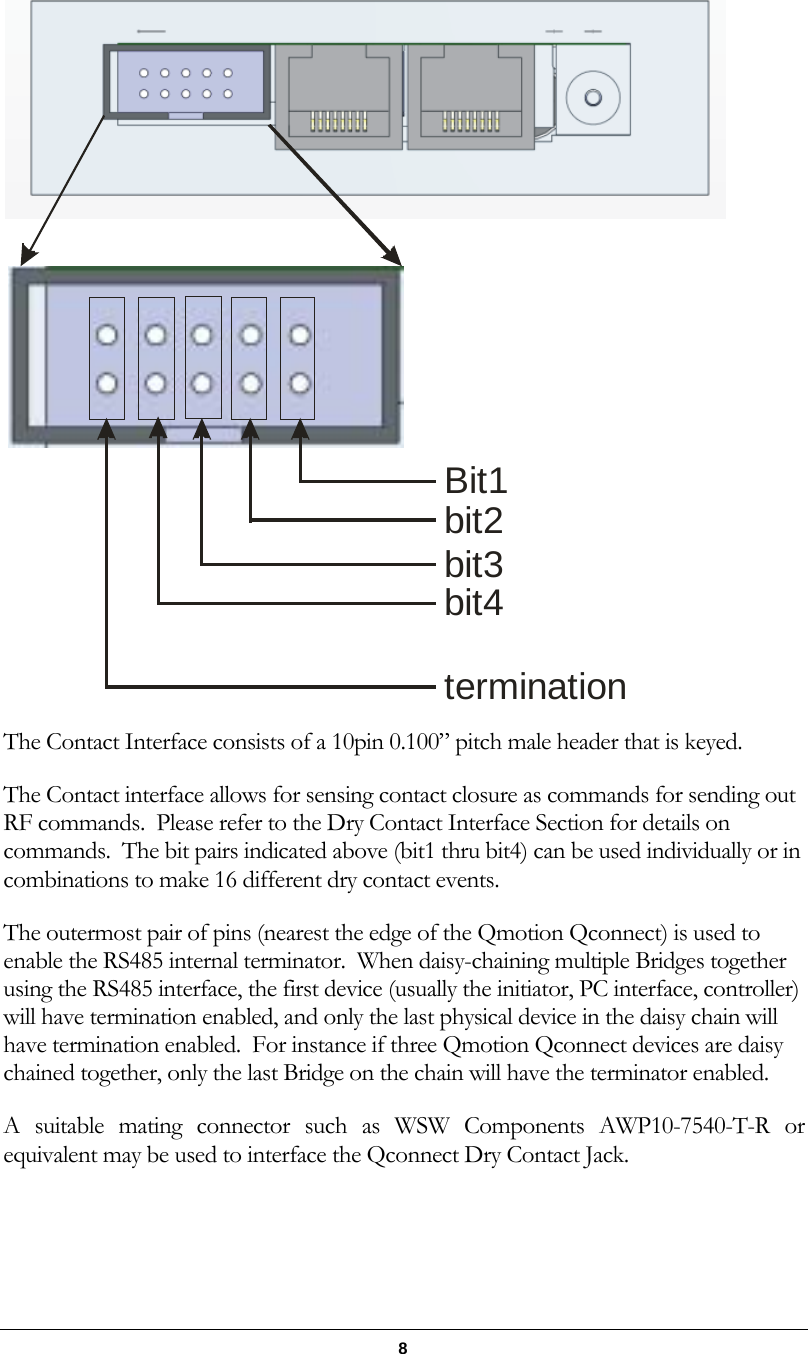
User Manual
Discussion / Help
Navigation